Hindawi Publishing Corporation International Journal of Distributed Sensor Networks Volume 2016, Article ID 8906985, 10 pages http://dx.doi.org/10.1155/2016/8906985
Research Article Optimization of LDPC Codes over the Underwater Acoustic Channel Shengxing Liu1,2 and Aijun Song3 1
Department of Applied Marine Physics and Engineering, Xiamen University, Xiamen 361102, China Key Laboratory of Underwater Acoustic Communication and Marine Information Technology, Ministry of Education, Xiamen University, Xiamen 361102, China 3 Department of Electrical and Computer Engineering, University of Alabama, Tuscaloosa, AL 35487, USA 2
Correspondence should be addressed to Shengxing Liu;
[email protected] Received 27 November 2015; Accepted 31 January 2016 Academic Editor: Roee Diamant Copyright © 2016 S. Liu and A. Song. This is an open access article distributed under the Creative Commons Attribution License, which permits unrestricted use, distribution, and reproduction in any medium, provided the original work is properly cited. To combat severe intersymbol interference incurred by multipath propagation of sound waves in the underwater acoustic environment, we introduce an iterative equalization and decoding scheme by iteratively exchanging soft information between a low-density parity check (LDPC) decoder and a decision feedback equalizer. We apply extrinsic information transfer (EXIT) charts to analyze performance of LDPC codes over the acoustic multipath channel. Furthermore, using differential evolution technique, we develop an EXIT-aided method to optimize LDPC codes for the underwater acoustic channel. Design examples are presented for two different realizations of the underwater acoustic channel that are generated by an acoustic ray tracing model. Computer simulations show that the optimized LDPC codes outperform its regular counterpart or Turbo codes under the same coding rate and block length, with gains of 1.0 and 0.8 dB, respectively, at the bit error rate of 10−5 .
1. Introduction Underwater acoustic communications have attracted much attention in recent years due to their broad application perspectives in the civil and defense domains. Applications may include oceanographic data collection, ocean pollution monitoring, ocean exploration, and subsea tactical surveillance [1–4]. However, it is a challenging task to achieve reliable communication due to the difficulties imposed by the acoustic propagation physics. The major difference between the underwater acoustic and radio frequency electromagnetic channels is that the former is characterized by large multipath delays and Doppler dispersion. Most of the difficulties can be attributed to the low speed of sound 1500 m/s in the seawater, which is five orders of magnitude slower than the speed of electromagnetic waves [5, 6]. Decision feedback equalizers (DFEs) are commonly used to combat intersymbol interference associated with multipath fading in the underwater acoustic channel. An adaptive DFE based on the combined recursive least square (RLS) and second-order phase-locked loop was developed for
high-rate underwater acoustic communication systems [7]. Experiments conducted in multiple environments demonstrated significant data rate and performance advancements. An adaptive multichannel combining and DFE equalization scheme was proposed in [8]. Near optimal spatial and temporal processing was proposed through joint minimum mean-squared error (MMSE) multichannel combining and equalization. Multichannel processing of underwater acoustic communication signals often leads to high computational costs. Complexity reduction was achieved by exploiting trade-offs between optimal diversity combining and beamforming in [9]. A sparse DFE structure that exploits the channel sparsity was developed in [10], to reduce receiver complexity. Powerful error correcting coding techniques are often employed to further reduce the bit error rate (BER) in the challenging underwater acoustic channel conditions. Due to channel variability resulting from environmental fluctuations such as ocean mixing and dynamic surface waves, the DFE alone cannot achieve adequate performance for practical communication applications. For example, a BER
2 of less than 10−3 is required for digital voice communication systems to synthesize natural speech. Convolution codes and Reed Solomon block codes are commonly used for real-time underwater acoustic communication system due to their simplicity. These codes were still not adequate to satisfy the BER requirement [11, 12]. Space-time trellis codes, layered space-time codes, and their combinations scheme were developed for high reliability and high data rate communications [13]. Turbo equalizer that jointly performs channel estimation, maximum a posteriori (MAP) equalization, and channel decoding was introduced for single-carrier coherent underwater acoustic communication [14, 15]. Several efforts have reported applying low-density parity check (LDPC) codes to the underwater acoustic environment, mostly for orthogonal frequency division multiplexing (OFDM) systems [3, 16]. In [16], nonbinary LDPC codes were proposed to enhance performance of uncoded orthogonal frequency division multiplexing (OFDM) communication for the underwater acoustic environment. In [3], LDPC decoding is coupled with soft minimum mean square error (MMSE) equalization for iterative detection on each subcarrier for multiple-antenna OFDM communications in the ocean. Irregular LDPC codes with an appropriate degree distribution may outperform Turbo codes under the same coding rate and block length [17]. However, LDPC codes exhibit a noise threshold phenomenon [18], when the iterative belief propagation decoding algorithm is used. If the channel noise level is smaller than, or below, a noise threshold, the BER converges to zero as the block length goes to infinity. Otherwise, an error floor exists. When the belief propagation algorithm is adopted to decode LDPC codes, extrinsic information is exchanged iteratively between the variable nodes and check nodes. Performance of LDPC codes converges as the iteration number increases. We can analyze the performance and, thus, determine their noise threshold by tracing evolution of the exchanged extrinsic information. Two types of methods, the density evolution algorithm [17] and extrinsic information transfer (EXIT) chart [19], can be used to calculate the noise threshold. The density evolution algorithm determines the threshold by tracing the evolution of the variables’ average distributions, under the assumption that the extrinsic information exchanged between the variable nodes and check nodes is independent random variables [17]. The density evolution algorithm has been widely used for analyzing and designing LDPC codes over different channels. Through the density evolution algorithm and related optimization techniques, multiple highperformance LDPC codes and their noise thresholds were given for the additive white Gaussian noise (AWGN) and binary symmetric channel in [17], and for flat Raleigh fading channel in [20]. However, these LDPC codes may not yield quality performance for intersymbol interference channels [21]. The density evolution algorithm was extended to investigate the limit of performance of LDPC codes over binary linear intersymbol interference channels with AWGN [22]. A simplified version of the density evolution algorithm, namely, the Gaussian approximation, was developed by
International Journal of Distributed Sensor Networks approximating message densities as Gaussians (for regular LDPC codes) or Gaussian mixtures (for irregular LDPC codes) [23]. This is to reduce the computational load involved in calculation of noise threshold as well as in optimization of degree distributions in the density evolution algorithm. Further, these tasks are often difficult for common channel conditions. This simplification provides a faster solution to calculate the noise threshold and an easier way to design optimized LDPC codes for the AWGN channel. The EXIT chart was developed initially to analyze the performance of parallel concatenated codes by tracing evolution of average mutual information [19]. It was extended to analyze the performance of LDPC codes by matching the EXIT curves of the variable nodes decoder (VND) and those of the check nodes decoder (CND) [24]. Optimized LDPC codes were designed for the AWGN channel and for the multiple-input and multiple-output (MIMO) setting [24]. High-quality LDPC codes via optimization of the EXIT charts were given for a flat Rayleigh fading channel in [25], for the Poisson pulse-position modulation channel in [26], and for high-dimension MIMO channels in [27]. Compared with the density evolution algorithm, the EXIT chart is simple in implementation. It can be readily applied to multipath environments, for example, the underwater acoustic channel. Here we focus our efforts on a single-carrier communication system in the underwater acoustic environment. The underwater acoustic channel generally contains both deterministic and stochastic properties. In a typical scenario, the deterministic characteristics are dependent on the sound frequency, surface and bottom acoustic properties, ocean sound speed profile, and location of transmitter and receiver. It means that the multipath or impulse response of the underwater acoustic channel may be quite different from one to another. The stochastic characteristics result from the rough and time-varying sea surface. We deal with the underwater acoustic channel at different transmission ranges. We use the BELLOP ray tracing model [28] to generate the impulse responses of specific channel realizations. We employ a DFE to process the received signal first and then adopt belief propagation algorithm to decode the information bits. To further improve performance, an iterative equalization and decoding scheme, termed as iterative DFELDPC structure, is proposed. In the DFE-LDPC structure, the soft information from the LDPC decoder is fed to the DFE as prior information. Since the DFE utilizes the channel information, as well as the soft information from the LDPC decoder, performance of the iterative scheme enhances with iterations. Limited investigations have been devoted to LDPC codes for single-carrier systems in the acoustic channel. One related effort was presented in [29], where soft-decision feedback equalization was combined with LDPC codes to provide robust detection performance for MIMO communications with different modulations schemes at different symbol rates, over different transmission ranges in the ocean. In this paper, we extend the EXIT chart to analyze the performance of LDPC codes over the underwater acoustic channel. Since performance of LDPC codes is strongly related to degree distributions and different impulse responses may have different appropriate degree distributions, we propose
International Journal of Distributed Sensor Networks
3 0 20 Depth (m)
0 10 20
Depth (m)
30
40 60 80
40
100 0.0
50
0.2
0.4 0.6 Distance (km)
0.8
1.0
1.6
2.0
(a)
60 0 70 20
90 100
1520
1525 1530 Sound speed (m/s)
Depth (m)
80
40 60 80 100 0.0
0.4
0.8 1.2 Distance (km) (b)
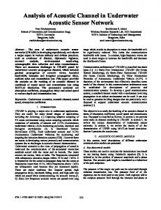
Figure 1: Ray diagrams of the communication ranges: (a) UWAC1 and (b) UWAC2.
an EXIT-aided optimization for specific channel realizations. Optimization of LDPC codes often turns into minimization of a nonlinear cost function, where differential evolution has been shown to be effective and robust [30]. Differential evolution has been successfully applied to optimization of LDPC codes for both the AWGN [17] and flat Raleigh fading channel [20]. We show that this technique is also effective for the underwater acoustic channel. Design examples are given for two different realizations. Performance comparisons among the optimized LDPC codes, regular LDPC code, and Turbo code are provided over the two different channel realizations. The remainder of the paper is organized as follows. The underwater acoustic channel model is introduced and two impulse responses are given in Section 2. The iterative DFE-LDPC structure and its EXIT charts are presented in Section 3. Section 4.1 discusses the EXIT-aided method of code optimization by using the differential evolution technique. Section 4.2 presents design examples of LDPC codes. Section 5 provides the conclusion.
2. Underwater Acoustic Channel Model Transmission characteristics of the underwater acoustic channels are affected by multiple factors, including the operating frequency, sound speed profile, sea surface conditions,
bathymetry, sediment properties, and source-receiver geometry and its mobility. BELLHOP is a beam tracing model for predicting underwater acoustic sound propagation [28]. With known physical parameters of the ocean environment and source-receiver settings, both time-invariant and time-varying impulse responses can be simulated efficiently through the use of the model [28, 31]. We focus on investigating the effects of multipath propagation on the performance of LDPC codes. Only time-invariant impulse responses, therefore, are considered in this paper. In the simulating impulse response, we assume flat sea surface and ocean bottom in 100 m water depth, with sound speed profile shown in Figure 1, left [32]. We assume the ocean silt bottom with a sound speed of 1600 m/s and a density of 1.1 km/m3 , and an attenuation coefficient of 0.8 dB/m. We assume a maximum sea surface wind speed of 10 m/s to infer the reflection characteristics. The transmitting and receiving nodes are positioned at 10 and 80 m above the seafloor. The acoustic operating frequency is 15 kHz. We consider two communication ranges, 1 and 2 km, to investigate the multipath structures and their impacts on equalization performance. The two associated impulse responses are referred to as UWAC1 and UWAC2, respectively, throughout the paper. Figures 1 and 2 show the ray diagrams and the two impulse responses for the ranges.
4
International Journal of Distributed Sensor Networks
1.0 Normalized amplitude
Normalized amplitude
1.0 0.8 0.6 0.4 0.2 0.0
0.8 0.6 0.4 0.2
0
10
20
30 40 50 Delay (ms)
60
70
80
0.0
0
10
20
30 40 50 Delay (ms)
(a)
60
70
80
(b)
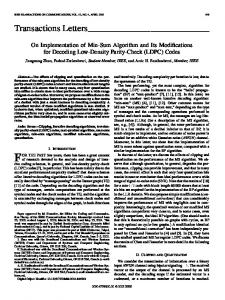
Figure 2: Impulse responses: (a) UWAC1 and (b) UWAC2.
As shown, path numbers increase from 7 to 11 as the communication range increases from 1 to 2 km. The delay spread increases from 33 to 72 ms. In both cases, the amplitude of the channel tap gets smaller at larger arrival delay, due to loss resulting from sea surface reflection and bottom attenuation. Compared with bottom attenuation, the reflection loss from the sea surface is more severe, due to the high acoustic operating frequency and a relatively high wind speed. Let the impulse response of the underwater acoustic channel be given by 𝐿−1
ℎ (𝑡) = ∑ 𝐴 𝑙 𝛿 (𝑡 − 𝜏𝑙 ) ,
(1)
𝑙=0
where 𝐿 is the number of channel taps and 𝐴 𝑙 and 𝜏𝑙 are the amplitude and time-delay of the 𝑙th taps, respectively. Then, the received signal 𝑦(𝑡) is 𝐿−1
𝑦 (𝑡) = ∑ 𝐴 𝑙 𝑥 (𝑡 − 𝜏𝑙 ) + 𝑤 (𝑡) ,
(2)
decoding result from the LDPC decoder is fed back to the DFE as a priori information. Based on the received signal and the a priori information, the DFE improves its performance. The LDPC decoder then enhances its decoding performance, as a result. This iterative process goes on until the termination criterion is met: that is, the iteration number is greater than the maximum iteration number, or decoding is successful. In this structure, two different iterative processes exist. One is the iteration between the VND and the CND within LPDC decoding. The other is the iteration between the DFE and the LDPC decoder. Two iterations are referred to as the inner and outer iterative processes, respectively. We set the inner and outer maximum iteration number to 2 and 20, respectively, in our simulations. Figure 3 also illustrates the flow of information exchanging between the LDPC decoder and the DFE and those within the LDPC decoder. The DFE performs detection by considering all 2𝑀 modulation constellation possible hypotheses on the symbol 𝑠. The DFE computes the log-likelihood ratio (LLR):
𝑙=0
where 𝑥(𝑡) is the transmitted signal and 𝑤(𝑡) is the ocean ambient noise. The ocean ambient noise may include turbulent noise, shipping traffic noise, thermo noise, and wind driven noise [33]. We assume 𝑤(𝑡) as the AWGN here.
3. Iterative DFE-LDPC Structure and Its EXIT Charts We propose an iterative equalization and decoding scheme, referred to as iterative DFE-LDPC structure, to combat the sever multipath in the underwater acoustic channel. We obtain EXIT charts of the DFE-LDPC structure to analyze performance of the LDPC codes over the underwater acoustic channels. In the proposed structure shown in Figure 3, the received signal distorted by the underwater acoustic channel is first processed by a DFE and then applied by a LDPC decoder, during an initial iteration. At the next iterations, the soft
𝐿 ch = log (
𝑃 (𝑐𝑖 = 0 | y, c ) 𝑃 (𝑐𝑖 = 1 | y, c )
) , for 𝑖 = 1, 2, . . . , 𝑀, (3)
where 𝑐𝑖 is the 𝑖th coded bit mapped onto the vector symbol 𝑠 for the channel output y and c is the a priori information from the LDPC decoder. The EXIT function of DFE is given by 𝐼𝐸,DFE (𝐼𝐴,DFE ,
𝐸𝑏 , ℎ) , 𝑁0
(4)
where 𝐸𝑏 and 𝑁0 are signal and noise power, respectively; 𝐼𝐴,DFE and 𝐼𝐸,DFE are the a priori and a posteriori mutual information for the DFE, respectively. The EXIT curve of the DFE is very complex, since it depends not only on the channel state, but also on the parameters of the DEF. A closed-form solution cannot be obtained. It is possible to obtain the EXIT curve of the DFE by Monte Carlo simulations. If we assume that both the information exchanged between the DFE and the VND and the information
International Journal of Distributed Sensor Networks
5
exchanged between the VND and the CND satisfy a Gaussian distribution, the EXIT function of the VND with degree 𝑑V is given by 𝐼𝐸,VND (𝐼𝐴,VND , 𝑑V , 𝑅,
𝐸𝑏 , ℎ) 𝑁0
Variable node decoder
s(n)
(5) 2
2
= 𝐽 (√(𝑑V − 1) [𝐽−1 (𝐼𝐴,VND )] + [𝐽−1 (𝐼𝐸,DFE )] ) ,
IE,DFE DFE IA,DFE
where 𝐼𝐴,VND and 𝐼𝐸,VND are the a priori and the a posteriori mutual information of the VND, respectively; 𝑅 is code rate of the LDPC codes; and 𝐽(⋅) is a function of mutual information [24]. The EXIT function of the CND with degree 𝑑𝑐 is given by
−
VND
−
VND
IE,VND −
Π−1
IA,CND
Check node decoder CND
− IA,VND Π I E,CND
DFE and variable node decoder
Figure 3: Iterative DFE-LDPC structure with the information changing flow illustrated.
𝐼𝐸,CND (𝐼𝐴,CND , 𝑑𝑐 , 𝑅) (6)
= 1 − 𝐽 (√(𝑑𝑐 − 1)𝐽−1 (1 − 𝐼𝐴,CND )) ,
where 𝐼𝐴,CND and 𝐼𝐸,CND are the a priori and a posteriori mutual information of the CND, respectively. After one or more iterations, the a priori mutual information 𝐼𝐴,DFE of the DFE is given by 2
2
𝐼𝐴,DFE = 𝐽 (√𝑑V [𝐽−1 (𝐼𝐴,VND )] + [𝐽−1 (𝐼𝐸,DFE )] ) ,
(7)
where 𝐼𝐸,DFE is the mutual information from the last step iteration. For irregular LDPC codes, the EXIT curve of the VND is the weighted average of all EXIT curves of the VND with degree 𝑑𝑖 (𝑖 = 2, 3, . . . , 𝑑V,max ): that is, 𝐼𝐸,VND (𝐼𝐴,VND , 𝑅,
Hard decision Binary sink ̂s(n)
𝐸𝑏 , ℎ) 𝑁0
𝑑V,max
𝐸 = ∑ 𝜆 𝑖 𝐼𝐸,VND (𝐼𝐴,VND , 𝑖, 𝑅, 𝑏 , ℎ) , 𝑁 0 𝑖=2
(8)
where 𝑑V,max is the maximal degree of variable nodes and 𝜆 𝑖 is a parameter representing the proportion of edges for degree 𝑖 to total edges in the bipartite graph corresponding to the variable nodes. Similarly, the EXIT curve of the CND is the weighted average of all EXIT curves of the CND with degree 𝑑𝑗 (𝑗 = 2, 3, . . . , 𝑑𝑐,max ): that is, 𝑑𝑐,max
𝐼𝐸,CND (𝐼𝐴,VND , 𝑅) = ∑ 𝜌𝑗 𝐼𝐸,CND (𝐼𝐴,CND , 𝑗, 𝑅) ,
(9)
𝑗=2
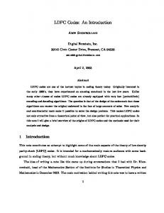
where 𝑑𝑐,max are the maximal degree of check nodes and 𝜌𝑗 is a parameter representing the proportion of edges for degree 𝑗 to total edges in the bipartite graph corresponding to the checks nodes. In Monte Carlo simulations, it is easy to obtain the EXIT curves of the VND through (5) and the EXIT curves of the CND through (6). Figure 4 shows the EXIT curves at the coding rate 𝑅 = 1/2 and SNR 𝐸𝑏 /𝑁0 = 7 dB over the two impulse responses: UWAC1 and UWAC2. In the calculation,
the DFE has 100 taps which include 50 taps for feedback filter and 50 for forward filter. The recursive least squares (RLS) algorithm with a forget factor of 0.95 is adopted to update the DFE filter coefficients. As shown, the EXIT curves of the VND vary over the degree of variable nodes. Their patterns change differently for the types of impulse responses, even under the same SNR, coding rate, and DFE parameters. However, the EXIT curves of the CND are related only to the degree of the check nodes.
4. Optimization of LDPC Codes By matching the EXIT curves of the VND to those of the CND, we can analyze coding performance and obtain noise threshold for any kind of LDPC codes over the underwater acoustic channel. Furthermore, good LDPC codes can be found through the use of an optimization algorithm to search for the highest noise threshold in a degree distribution space. The searching process is very complex because there are many parameters to be determined simultaneously. The differential evolution is a fairly fast and reasonably robust method that optimizes the solution by iterating candidate solutions for a given measure of quality [30]. We use the differential evolution technique to search an optimized LDPC code here. 4.1. Differential Evolution Algorithm. Considering the fact that the performance of a LDPC code is related mainly to the degree distribution of the variable nodes, and little to the degree distribution of the check nodes, we assume that the number of degree for the check nodes is 1 (or 2), and its degree is 𝑑𝑐 (or 𝑑𝑐 and 𝑑𝑐 + 1) for simplicity. The number of degree for the variable nodes is greater than or equal to 3 and keeps invariable in the process of optimization. If the parameters 𝜆 𝑖 (𝑖 = 2, 3, . . . , 𝑑V,max ) have been determined, then 𝑑𝑐 and its corresponding 𝜌𝑑𝑐 are determined by the following equation: 𝑑V,max
(1 − 𝑅) ∑ 𝑖=2
𝜆 𝑖 𝜌𝑑𝑐 1 − 𝜌𝑑𝑐 + = . 𝑖 𝑑𝑐 𝑑𝑐 + 1
(10)
International Journal of Distributed Sensor Networks 1.0
1.0
0.8
0.8
0.6
0.6 IA,CND
IE,VND
6
0.4
0.2
0.0 0.0
0.4
R = 1/2, Eb /N0 = 7.0 dB
0.2
R = 1/2, Eb /N0 = 7.0 dB 0.2
0.4
0.6
0.8
1.0
0.0 0.0
0.2
IA,VND
0.4
0.6
0.8
1.0
IE,CND
UWAC1 UWAC2
UWAC1 UWAC2 (a)
(b)
Figure 4: EXIT curves of the iterative DFE-LDPC structure over the two types of impulse responses: (a) EXIT curves of the VND and (b) EXIT curves of the CND.
With the constraint in (10), the differential evolution algorithm for searching good degree distribution of the LDPC codes is described as follows.
Table 1: Optimized parameters of LDPC codes over the two types of impulse responses. Parameters
Initialization (i) Choose distinct 𝐷 integers from set {2, 3, . . . , 𝑑V,max } as the degrees of the variable node. It is noted that the three numbers, 2, 3, and 𝑑V,max , must be chosen, and the other 𝐷-3 numbers are chosen randomly from the remaining numbers. (ii) For the initial iteration 𝑘 = 0, randomly generate 𝑀 (𝑀 ≥ 10𝐷) D-dimensional vectors U𝑚,𝑘 , 𝑚 = 0, 1, . . . , 𝑀 − 1, with sum of elements being equal to 1. For each vector U𝑚,𝑘 , we obtain its corresponding noise threshold 𝜎𝑚,𝑘 of LDPC code by matching the EXIT curves of the VND to those of the CND. We label the largest 𝜎𝑚,𝑘 as 𝜎best,𝑘 , and its corresponding vector as Ubest,𝑘 . (1) Mutation. For each 𝑚 = 0, 1, . . . , 𝑀 − 1, randomly choose distinct four integers 𝑚1, 𝑚2, 𝑚3, and 𝑚4 from set {0, 1, . . . , 𝑀 − 1}, each different from the index. Define V𝑚,𝑘 = Ubest,𝑘 + 𝐹 (U𝑚1,𝑘 − U𝑚2,𝑘 + U𝑚3,𝑘 − U𝑚4,𝑘 ) ,
(11)
where 𝐹 is the real constant to control the amplification of the differential variation. We choose 𝐹 = 0.5 in our optimization. For each V𝑚,𝑘 , we obtain its corresponding noise threshold of LDPC code by matching the EXIT curves of the VND 𝜎𝑚,𝑘 as 𝜎best,𝑘 , and to those of the CND. We label the largest 𝜎𝑚,𝑘 its corresponding vector as Vbest,𝑘 . (2) Evolution. For the 𝑘 + 1 iteration, if 𝜎𝑚,𝑘 is smaller than , U𝑚,𝑘+1 is set to V𝑚,𝑘 ; otherwise, U𝑚,𝑘+1 is set to U𝑚,𝑘 . 𝜎𝑚,𝑘
𝜆2 𝜆3 𝜆 20 𝜌9 𝜌10 𝜎th (𝐸𝑏 /𝑁0 )th
Realizations UWAC1 0.1210 0.3788 0.5002 0.5300 0.4700 0.4416 7.1 dB
UWAC2 0.1290 0.3846 0.4863 0.7671 0.2329 0.4624 6.7 dB
If 𝜎best,𝑘 is smaller than 𝜎best,𝑘 , 𝜎best,𝑘+1 is set to 𝜎best,𝑘 ; Ubest,𝑘+1 is set to Vbest,𝑘 . Otherwise, 𝜎best,𝑘+1 is set to 𝜎best,𝑘 ; Ubest,𝑘+1 is set to Ubest,𝑘 .
(3) Stop. If 𝑘 < 𝐾max , return to Step (2); otherwise, the process is terminated, where 𝐾max is the maximum iteration number of the process. At the exit, we label the vector with the highest noise threshold and regard it as the optimized degree distribution of the variable node. 4.2. Design Examples. To reduce the computational load, we restrict the variable nodes to only three distinct variable node degrees (𝐷 = 3). We also assume coding rate 𝑅 = 1/2 and 𝑑V,max = 20. Through the differential evolution algorithm presented in the previous subsection, we obtain the optimized LDPC codes for both the UWAC1 and the UWAC2 impulse responses. The optimized parameters and the best noise threshold are shown in Table 1. In Table 1, variable 𝜎th is the noise threshold of the optimized LDPC codes, and (𝐸𝑏 /𝑁0 )th is the corresponding SNR. As shown in Table 1, these channel realizations have the different
7
1.0
1.0
0.8
0.8 IE,VND , IA,CND
IE,VND , IA,CND
International Journal of Distributed Sensor Networks
0.6
0.4
0.2
0.6
0.4
0.2 R = 1/2, Eb /N0 = 7.1 dB
0.0 0.0
0.2
R = 1/2, Eb /N0 = 6.7 dB
0.4 0.6 IA,VND , IE,CND
0.8
0.0 0.0
1.0
VND CND
0.2
0.4 0.6 IA,VND , IE,CND
0.8
1.0
VND CND (a)
(b)
Figure 5: EXIT charts for LDPC codes over two channel realizations: (a) UWAC1 and (b) UWAC2.
10−2
10−2
10−3
10−3
BER
10−1
BER
10−1
10−4
10−4
10−5
10−5
10−6 6.0
6.5
7.0
7.5
8.0 Eb /N0
Uncoded Turbo Reg3
8.5
9.0
9.5
10.0
Irreg1 Irreg2 (a)
10−6 6.0
6.5
7.0
7.5
8.0 Eb /N0
Uncoded Turbo Reg3
8.5
9.0
9.5
10.0
Irreg1 Irreg2 (b)
Figure 6: Performance of the optimized LDPC codes, regular LPDC code, and Turbo code over the two channel realizations: (a) UWAC1 and (b) UWAC2.
optimized parameters as well as the best noise threshold for LDPC codes. For example, 𝜎th is 0.4416 for the UWAC1 impulse response, with a corresponding (𝐸𝑏 /𝑁0 )th of 7.1 dB, which is 0.4 dB higher than that for the UWAC2 impulse response. Figure 5 shows the EXIT curves of the optimized LDPC codes over the UWAC1 and UWAC2 channel realizations. In Figure 5, both the EXIT curves of the VND and the CND converge to 1 as the a priori mutual information increases. The EXIT curve of the VND follows very closely the EXIT curve of the CND from the above, when the SNR (𝐸𝑏 /𝑁0 ) is greater
than the SNR (𝐸𝑏 /𝑁0 )th . This implies that the optimized LDPC code is able to be decoded successfully for any given value of the a priori mutual information 𝐼𝐴,VND in this case. However, the curve of the VND intersects with that of the CND if the SNR 𝐸𝑏 /𝑁0 is lower than the threshold SNR (𝐸𝑏 /𝑁0 )th , which indicates that the optimized LDPC code cannot be decoded successfully for any iterations in this case. Figure 6 gives the simulation results for the optimized LDPC codes over the two channel realizations. In Figure 6, the symbols “Irreg1” and “Irreg2” represent the optimized LDPC codes for the two cases: UWAC1 and UWAC2
8
International Journal of Distributed Sensor Networks
10−2
10−2
10−3
10−3
BER
10−1
BER
10−1
10−4
10−4
10−5
10−5
10−6 6.0
6.5
7.0
7.5
8.0 Eb /N0
Uncoded Turbo Reg3
8.5
9.0
9.5
10.0
Irreg1 Irreg2
10−6 6.0
6.5
7.0
7.5
8.0 Eb /N0
Uncoded Turbo Reg3
(a)
8.5
9.0
9.5
10.0
Irreg1 Irreg2 (b)
Figure 7: Performance of the optimized LDPC codes, regular LPDC code, and Turbo code over the two channel realizations in colored noise: (a) UWAC1 and (b) UWAC2.
realizations, respectively. “Reg3” represents a regular LDPC code with 3 degrees for variable node. “Turbo” represents a Turbo code with constraint lengths of 4, and “Uncoded” indicates the performance of an uncoded system. We use progressive edge-growth algorithm to construct the parity check matrix. The belief propagation algorithm is used to decode the LDPC codes while Log-MAP algorithm is used to decode the Turbo code. All constructed codes have a coding rate of 𝑅 = 1/2 and a block length of 𝑛 = 8000. The symbol duration is 1 ms and, therefore, the symbol rate is 1 kHz. The modulation is binary phase shift keying (BPSK). Two hundred (200) training symbols are used for training the DFE. The iterative decoding is done by two DFE/decoder iterations and 20 internal decoder iterations per DFE/decoder iteration. As shown in Figure 6, the optimized LDPC codes outperform both the regular LDPC code and the Turbo code under the same coding rate and block length. The achieved gains are about 1.0 dB and 0.8 dB, respectively, at the BER of 10−4 in the two channel realizations. We note that the LDPC codes optimized for the UWAC1 realization also have quality performance for the UWAC2 realization and vice versa. Under the constraint of the limited block length and limited iteration count, a performance gap of about 1.3–1.5 dB is achieved between the numerical simulation and the noise threshold from the EXIT charts. Figure 7 shows performance of the optimized LDPC codes over two channel realizations with colored noise. The noise attenuates with sound frequency by 20 dB per octave. Due to the acoustic high frequency and narrow bandwidth, the optimized LDPC codes perform better than Turbo code and regular LDPC in this case. Comparing Figure 7 with Figure 6, we found that the DFE-LDPC receiver in colored noise has almost the same performance as in AWGN.
5. Conclusions The underwater acoustic channel is a complex, multipath fading environment. To achieve low BER performance for single-carrier coherent underwater acoustic communication systems, we introduce an iterative equalization and decoding scheme. Simulations demonstrate that the proposed scheme has ability to achieve excellent BER performance at low SNRs over two different multipath realizations. We extend the EXIT charts to the underwater acoustic channel to assess the performance of the LDPC codes. We propose an EXIT-aided method to optimize LDPC codes using the different evolution algorithm. Simulations show that BER of the optimized LDPC codes is less than 10−5 at 𝐸𝑏 /𝑁0 = 8.5 dB, achieving gains of 1.0 and 0.8 dB over the regular LDPC and Turbo codes, respectively, under the same coding rate and block length. Under the constraint of the limited block length and iteration count, a performance gap of about 1.3–1.5 dB is achieved between the numerical simulation and the noise threshold from the EXIT charts.
Conflict of Interests The authors declare that there is no conflict of interests regarding the publication of this paper.
Acknowledgments This work is supported by the National Natural Science Foundation of China (Project no. 41276038) and the China Scholarship Council (CSC).
International Journal of Distributed Sensor Networks
References [1] D. B. Kilfoyle and A. B. Baggeroer, “The state of the art in underwater acoustic telemetry,” IEEE Journal of Oceanic Engineering, vol. 25, no. 1, pp. 4–27, 2000. [2] T. C. Yang and W.-B. Yang, “Low probability of detection underwater acoustic communications using direct-sequence spread spectrum,” Journal of the Acoustical Society of America, vol. 124, no. 6, pp. 3632–3647, 2009. [3] B. Li, J. Huang, S. Zhou et al., “MIMO-OFDM for high-rate underwater acoustic communications,” IEEE Journal of Oceanic Engineering, vol. 34, no. 4, pp. 634–644, 2009. [4] A. Radosevic, R. Ahmed, T. M. Duman, J. G. Proakis, and M. Stojanovic, “Adaptive OFDM modulation for underwater acoustic communications: design considerations and experimental results,” IEEE Journal of Oceanic Engineering, vol. 39, no. 2, pp. 357–370, 2014. [5] J. A. Catipovic, “Performance limitations in underwater acoustic telemetry,” IEEE Journal of Oceanic Engineering, vol. 15, no. 3, pp. 205–216, 1990. [6] T. C. Yang, “Properties of underwater acoustic communication channels in shallow water,” Journal of the Acoustical Society of America, vol. 131, no. 1, pp. 129–145, 2012. [7] M. Stojanovic, J. A. Catipovic, and J. G. Proakis, “Phasecoherent digital communications for underwater acoustic channels,” IEEE Journal of Oceanic Engineering, vol. 19, no. 1, pp. 100– 111, 1994. [8] M. Stojanovic, J. Catipovic, and J. G. Proakis, “Adaptive multichannel combining and equalization for underwater acoustic communications,” The Journal of the Acoustical Society of America, vol. 94, no. 3, pp. 1621–1631, 1993. [9] M. Stojanovic, J. A. Catipovic, and J. G. Proakis, “Reducedcomplexity spatial and temporal processing of underwater acoustic communication signals,” Journal of the Acoustical Society of America, vol. 98, no. 2, pp. 961–972, 1995. [10] M. Kocic, D. Brady, and M. Stojanovic, “Sparse equalization for real-time digital underwater acoustic communications,” in Proceedings of the MTS/IEEE OCEANS ’95, pp. 1417–1422, San Diego, Calif, USA, October 1995. [11] A. Goalic, J. Trubuil, and N. Beuzelin, “Channel coding for underwater acoustic communication system,” in Proceedings of the MTS/IEEE (OCEANS ’06), pp. 1–4, IEEE, Boston, Mass, USA, September 2006. [12] J. Park, C. Seo, K.-C. Park, and J. R. Yoon, “Effectiveness of convolutional code in multipath underwater acoustic channel,” Japanese Journal of Applied Physics, vol. 52, no. 7, 2013. [13] S. Roy, T. M. Duman, V. McDonald, and J. G. Proakis, “High-rate communication for underwater acoustic channels using multiple transmitters and space—time coding: receiver structures and experimental results,” IEEE Journal of Oceanic Engineering, vol. 32, no. 3, pp. 663–688, 2007. [14] E. M. Sozer, J. G. Proakis, and F. Blackmon, “Iterative equalization and decoding techniques for shallow water acoustic channels,” in Proceedings of the MTS/IEEE Conference and Exhibition for Ocean Engineering, Science and Technology (OCEANS ’01), vol. 4, pp. 2201–2208, Honolulu, Hawaii, USA, November 2001. [15] R. Otnes and T. H. Eggen, “Underwater acoustic communications: long-term test of turbo equalization in shallow water,” IEEE Journal of Oceanic Engineering, vol. 33, no. 3, pp. 321–334, 2008.
9 [16] J. Huang, S. Zhou, and P. Willett, “Nonbinary LDPC coding for multicarrier underwater acoustic communication,” IEEE Journal on Selected Areas in Communications, vol. 26, no. 9, pp. 1684–1696, 2008. [17] T. J. Richardson, M. A. Shokrollahi, and R. L. Urbanke, “Design of capacity-approaching irregular low-density paritycheck codes,” IEEE Transactions on Information Theory, vol. 47, no. 2, pp. 619–637, 2001. [18] T. J. Richardson and R. L. Urbanke, “The capacity of lowdensity parity-check codes under message-passing decoding,” IEEE Transactions on Information Theory, vol. 47, no. 2, pp. 599– 618, 2001. [19] S. T. Brink, “Convergence behavior of iteratively decoded parallel concatenated codes,” IEEE Transactions on Communications, vol. 49, no. 10, pp. 1727–1737, 2001. [20] J. Hou, P. H. Siegel, and L. B. Milstein, “Performance analysis and code optimization of low density parity-check codes on Rayleigh fading channels,” IEEE Journal on Selected Areas in Communications, vol. 19, no. 5, pp. 924–934, 2001. [21] A. Thangaraj and S. W. McLaughlin, “Thresholds and scheduling for LDPC-coded partial response channels,” IEEE Transactions on Magnetics, vol. 38, no. 5, pp. 2307–2309, 2002. [22] A. Kavˇci´c, X. Ma, and M. Mitzenmacher, “Binary intersymbol interference channels: gallager codes, density evolution, and code performance bounds,” IEEE Transactions on Information Theory, vol. 49, no. 7, pp. 1636–1652, 2003. [23] S.-Y. Chung, T. J. Richardson, and R. L. Urbanke, “Analysis of sum-product decoding of low-density parity-check codes using a Gaussian approximation,” IEEE Transactions on Information Theory, vol. 47, no. 2, pp. 657–670, 2001. [24] S. T. Brink, G. Kramer, and A. Ashikhmin, “Design of lowdensity parity-check codes for modulation and detection,” IEEE Transactions on Communications, vol. 52, no. 4, pp. 670–678, 2004. [25] Y. Jiang, A. Ashikhmin, and N. Sharma, “LDPC codes for flat Rayleigh fading channels with channel side information,” IEEE Transactions on Communications, vol. 56, no. 8, pp. 1207–1213, 2008. [26] M. F. Barsoum, B. Moision, M. P. Fitz, D. Divsalar, and J. Hamkins, “EXIT function aided design of iteratively decodable codes for the poisson PPM channel,” IEEE Transactions on Communications, vol. 58, no. 12, pp. 3573–3582, 2010. [27] T. L. Narasimhan and A. Chockalingam, “EXIT chart based design of irregular LDPC codes for large-MIMO systems,” IEEE Communications Letters, vol. 17, no. 1, pp. 115–118, 2013. [28] M. B. Porter and H. P. Bucker, “Gaussian beam tracing for computing ocean acoustic fields,” The Journal of the Acoustical Society of America, vol. 82, no. 4, pp. 1349–1359, 1987. [29] A. Rafati, H. Lou, and C. Xiao, “Soft-decision feedback turbo equalization for LDPC-coded MIMO underwater acoustic communications,” IEEE Journal of Oceanic Engineering, vol. 39, no. 1, pp. 90–99, 2014. [30] R. Storn and K. Price, “Differential evolution—a simple and efficient heuristic for global optimization over continuous spaces,” Journal of Global Optimization, vol. 11, no. 4, pp. 341– 359, 1997. [31] M. Siderius and M. B. Porter, “Modeling broadband ocean acoustic transmissions with time-varying sea surfaces,” The Journal of the Acoustical Society of America, vol. 124, no. 1, pp. 137–150, 2008.
10 [32] J. W. Choi and P. H. Dahl, “Measurement and simulation of the channel intensity impulse response for a site in the East China Sea,” Journal of the Acoustical Society of America, vol. 119, no. 5, pp. 2677–2685, 2006. [33] M. Stojanovic, “On the relationship between capacity and distance in an underwater acoustic communication channel,” in Proceedings of the 1st ACM International Workshop on Underwater Networks (WUWNet ’06), pp. 41–47, New York, NY, USA, September 2006.
International Journal of Distributed Sensor Networks
International Journal of
Rotating Machinery
Engineering Journal of
Hindawi Publishing Corporation http://www.hindawi.com
Volume 2014
The Scientific World Journal Hindawi Publishing Corporation http://www.hindawi.com
Volume 2014
International Journal of
Distributed Sensor Networks
Journal of
Sensors Hindawi Publishing Corporation http://www.hindawi.com
Volume 2014
Hindawi Publishing Corporation http://www.hindawi.com
Volume 2014
Hindawi Publishing Corporation http://www.hindawi.com
Volume 2014
Journal of
Control Science and Engineering
Advances in
Civil Engineering Hindawi Publishing Corporation http://www.hindawi.com
Hindawi Publishing Corporation http://www.hindawi.com
Volume 2014
Volume 2014
Submit your manuscripts at http://www.hindawi.com Journal of
Journal of
Electrical and Computer Engineering
Robotics Hindawi Publishing Corporation http://www.hindawi.com
Hindawi Publishing Corporation http://www.hindawi.com
Volume 2014
Volume 2014
VLSI Design Advances in OptoElectronics
International Journal of
Navigation and Observation Hindawi Publishing Corporation http://www.hindawi.com
Volume 2014
Hindawi Publishing Corporation http://www.hindawi.com
Hindawi Publishing Corporation http://www.hindawi.com
Chemical Engineering Hindawi Publishing Corporation http://www.hindawi.com
Volume 2014
Volume 2014
Active and Passive Electronic Components
Antennas and Propagation Hindawi Publishing Corporation http://www.hindawi.com
Aerospace Engineering
Hindawi Publishing Corporation http://www.hindawi.com
Volume 2014
Hindawi Publishing Corporation http://www.hindawi.com
Volume 2014
Volume 2014
International Journal of
International Journal of
International Journal of
Modelling & Simulation in Engineering
Volume 2014
Hindawi Publishing Corporation http://www.hindawi.com
Volume 2014
Shock and Vibration Hindawi Publishing Corporation http://www.hindawi.com
Volume 2014
Advances in
Acoustics and Vibration Hindawi Publishing Corporation http://www.hindawi.com
Volume 2014