Probing the Electrical Properties of Overlapped Graphene Grain Boundaries by Raman spectroscopy Rahul Rao,* Neal Pierce, Avetik R. Harutyunyan Honda Research Institute USA, Columbus, OH, USA 43212
Correspondence –
[email protected]
Abtract The effect of grain boundaries and wrinkles on the electrical properties of polycrystalline graphene is pronounced.
Here we investigate the stitching between grains of
polycrystalline graphene, specifically, overlapping of layers at the boundaries, grown by chemical vapor deposition (CVD) and subsequently doped by the oxidized Cu substrate. We analyze overlapped regions between 60 – 220 nm wide via Raman spectroscopy, and find that some of these overlapped boundaries contain AB–stacked bilayers. The Raman spectra from the overlapped grain boundaries are distinctly different from bilayer graphene and exhibit splitting of the G band peak. The degree of splitting, peak widths, as well as peak intensities depend on the width of the overlap. We attribute these features to inhomogeneous doping by charge carriers (holes) across the overlapped regions via the oxidized Cu substrate. As a result, the Fermi level at the overlapped grain boundaries lies between 0.3 and 0.4 eV below the charge neutrality point. Our results suggest an enhancement of electrical conductivity across overlapped grain boundaries, similar to previously observed measurements[1]. The dependence of charge distribution on the
1
width of overlapping of grain boundaries may have strong implications for the growth of large-area graphene with enhanced conductivity. 1. Introduction The continuity of polycrystalline graphene and the minimization of its grain boundaries (GBs) remains a big challenge towards its integration into large-scale applications [2-5]. Recent reports indicate that the stitching, or connection between grains in graphene grown by CVD has a significant impact on the electrical transport across the GBs [1,6-9] as well as the mechanical integrity of graphene films [10]. Moreover, GBs in graphene are known to be high-reactivity sites[11], and have been observed to induce a higher degree of oxidation of the underlying copper substrates [12-14]. As a result, much effort has been directed towards the growth of large area graphene films by the suppression of nucleation sites [4,15-18]. At the atomic level the interconnection between graphene grains in CVD-grown graphene has been shown to comprise of alternating pentagons and heptagons along the seams [19,20]. However, in addition to atomic bonding between graphene grains, graphene grains have also been observed to overlap each other when the grain growth rate is sufficiently low. Overlapped grains up to 1 µm in width have been observed [1,21]. Surprisingly, the electrical transport across the overlapped GB can be better than the atomically interconnected (and disordered) grain boundary, with the electrical conductance an order of magnitude higher [1]. This result from Ref. 1 suggests that the creation of GBs with engineered widths would potentially be an exciting advance towards achieving continuous electrical conductivity across large-area polycrystalline graphene
2
films. Although the atomic structure of these overlapped GBs is not fully known, evidence for misoriented stacking between the overlapped layers in few layer graphene samples has been found by high-resolution transmission electron microscopy (HRTEM) [22]. In addition to graphene, overlapped grains have also recently been observed in CVD-grown MoS2 [23,24], although their impact on properties is not known. Overlaps between 2D layers during growth could be universal, and the possibility of electrically conductive overlaps across narrow atomic layers hints at the prospect of utilizing these nanoribbons in a variety of exciting applications. Here we investigate the electronic properties of a particular set of overlapped GBs between graphene grains on oxidized Cu substrates by Raman spectroscopy. GBs with overlap widths varying between 60 and 220 nm are first mapped by scanning electron microscopy (SEM) and Raman spectra collected from the GBs as well as adjacent graphene grains for comparison. In our doped samples a small percentage of overlapped GBs (5 as observed in pristine graphene on Cu [32]. A low IG’/IG in graphene is also expected due to doping. A third dispersive peak which is typically observed due to disorder at ~1330 cm-1 (~1350 cm-1) with Elaser = 1.96 eV (with Elaser = 2.33 eV) [31] cannot be observed in the graphene Raman spectra, indicating a high degree of crystallinity in the graphene grains. The Raman spectrum from the GB in Fig. 1a is also blueshifted. However, the G’ peak from the GB is quite different from that of the nearby graphene region - the G’ peak exhibits a complex lineshape and can be deconvoluted into four Lorentzian peaks instead of a single peak. The four-Lorentzian peak G’ band lineshape is unique to BLG [30,31], and strongly suggests that the overlapped GB consists of two graphene layers with Bernal (or AB) stacking between the layers. In other words, the two graphene grains are bounded by a narrow BLG nanoribbon. This result is in contrast to the previous HRTEM study that reported stacking faults at the boundaries between graphene layers in a few layer graphene sample [22]. The difference in stacking order across the overlapped region in our sample compared to Ref. 22 could be due to the different growth rates or CVD
7
method employed (the CVD process employed in Ref. 22 produced multi-layer graphene). It is known that atmospheric pressure CVD produces nearly hexagonal graphene grains with straight edges. In the event that the edges of two growing hexagonal grains line up parallel to each other during growth, one grain could overlap another and retain commensurate stacking between the two grains. In our samples the overlapped GBs that exhibit Raman spectra corresponding to AB-stacked BLG are formed such that the edges of the two graphene grains are more or less parallel to each other (see an example in Fig. S1 with related discussion). We note that while our laser spot is ~ 1 µm in diameter, we are able to collect spectra from GBs whose widths are much lesser than the spot size. Linescans collected across several GBs (see for example Figs. S2 and S3) show the G’ band evolving from a single peak lineshape to a broadened, redshifted, and multi-peaked lineshape across the GB. In order to gain further insight into the nature of the peaks comprising the G’ band in the overlapped GBs, we measure the dispersion of their peak frequencies as a function of excitation laser energy. The four peaks in the G’ band from BLG typically have a dispersion of ~90 cm-1/eV for the laser energy range used in this study (1.96 – 2.41 eV) [31,37]. The dispersion of the four deconvoluted peaks within the G’ band from the BGs ranges from 73 – 80 cm-1/eV (Fig. S4) and is consistent with previously reported values for BLG [31,37], though lower than the values for pristine BLG. The lower values of the peak dispersions between the overlapped GBs and pristine BLG could be the result of disorder or strain (discussed further below). Such a lowering of peak dispersion has been observed previously in disordered single-walled carbon nanotubes [38]. We note that the lineshapes of the G’ bands in the overlapped GBs do not match the typical lineshapes
8
from BLG on Cu reported in the literature. Indeed the G’ band from BLG on Cu foil does not typically exhibit shoulders indicating multiple deconvoluted peaks; its lineshape appears more like a single peak, although broader than the G’ band from monolayer graphene [18]. Our observation of a complex multi-peak G’ band from the overlapped GBs, along with the dispersion of peak frequencies that agrees very well with the expected Raman response from BLG, therefore strongly suggests that these overlapped GBs are composed of AB-stacked BLG. We stress that the occurrence of AB-stacked overlapped GBs is not universal. They comprise a small percentage ( 0.2 eV), the G- peak is dominated by the anti-symmetric mode and is lower in intensity than the G+ peak [44]. We also observe distinct dependencies of the linewidths of the G- and G+ peaks on the GB overlap width. As shown in Fig. 4d, the G- and G+ peaks undergo broadening and sharpening, respectively, with increasing GB overlap. Such a contrasting behavior of the G- and G+ peak linewidths is not expected theoretically. However, it has been seen in BLG samples doped asymmetrically with sulfuric acid [47]. Additionally, broadening of the antisymmetric mode has been observed due to increased electron-phonon coupling in gated BLG [57, 58]. The dominant anti-symmetric mode at higher charge densities could thus account for the broadening we observe in the G- peak. Moreover, it is important to note that the previous studies were performed on BLG samples prepared by mechanical exfoliation. In our case the BLG is formed by the overlapping of two individual graphene grains during high temperature CVD growth, and is different from exfoliated BLG. Hence an exact explanation of the observed behavior of optical phonons in the overlapped GBs would require a careful study on their interaction with charges in a controlled (for example, gated) environment. In order to visualize the charge distribution across the overlapped GBs we perform conductive AFM across the overlapped GBs. Fig. 5a shows an SEM image of an overlapped grain boundary. Figs. 5b and 5c show the corresponding current and friction scans taken from the same area. Although the scans are noisy due to the roughness imparted by the oxidized Cu foil, a clear change in contrast can be observed in the area corresponding to the overlapped GB in both the current and friction scans. Moreover, the
17
linescans across the topography and friction maps show clear differences on and off the overlapped GB (Fig. S7).
a"
1" m"
c"
b"
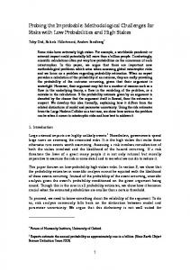
Fig. 5 – (a) SEM image of an overlapped GB and corresponding (b) current and (c) friction maps generated with conductive AFM. The vertical scales in (b) and (c) range from 0–10 nA and 0-10 mv, respectively.
18
Fig. 6 - Plot of GB overlap width versus estimated charge densities (bottom axis) and calculated Fermi level energies (top axis). Since the IG+/IG- ratio is expected to depend strongly on the charge concentration theoretically [43, 44], and is also observed experimentally (Fig. 4c and Ref. 47), we compare our IG+/IG- ratios with the previously published values and extract the corresponding charge densities (n). The densities increase with the width of the GB overlap from ~0.7 to 1.3 x 1013 cm-2. We also estimate the Fermi level corresponding to these charge densities according to the formula EF = -hvF(n/4π)1/2, where vF is the Fermi velocity = 1.1 x 10⁶ m2/s [59, 60]. The charge densities and calculated Fermi energies are plotted as a function of the GB overlap width in Fig. 6. Due to hole-doping we find Fermi levels ranging from -0.3 to -0.42 eV below the charge neutrality point as the GB overlap width increases from 60 to 220 nm. Oxygen intercalation in BLG has been previously
19
observed to induce p-type doping with charge densities similar to those observed in the present study [29, 61].
Fig. 6 – (a) Schematic showing inhomogeneous doping across the overlapped GBs with increasing width. The top and bottom layers are doped inhomogeneously from the oxidized Cu substrate. (b) Schematic band diagrams showing the location of the Fermi levels in undoped and p-doped BLG.
The splitting of the G band indicates that the bottom and top layers in the GB are doped differently. A schematic showing the inhomogeneous doping of the GB by the copper oxide substrate is shown in Fig. 7a. Increasing overlap causes greater doping of the bottom layer compared to the top graphene layer, thus enhancing the inhomogeneous doping of the GB. As a result the Fermi level drops below the neutrality point due to doping of the GB with holes, as shown in the schematic band diagrams in Fig. 7b. Our
20
study has shown the presence of AB-stacked bi-layer overlapped GBs between merged graphene grains grown by CVD. Raman spectra collected from several GBs indicates inhomogeneous hole doping from the oxidized Cu substrate. The inhomogeneous doping increases with the width of the overlap, thereby tuning the Fermi level of the GB between -0.3 and -0.42 eV. While thorough electrical transport measurements across several GBs would be useful, the observed increase in carrier densities across the AB-stacked overlapped GBs suggest continuous electrical conductivity across overlapped GBs in graphene samples. Furthermore, overlapped GBs with tunable widths and edge structures offer the opporunity to study the performance of BLG nanoribbons [25], as well as unique device geometries such as nanoribbon diodes with negative differential resistance [26] and electromechanical switches based on overlapping nanoribbons [27].
4. Conclusions We have utilized Raman spectroscopy to study overlapped GBs in various graphene grains grown by atmospheric pressure CVD. Raman spectra reveal the overlapped regions to be AB-stacked BLG. Oxidation of the Cu substrate was used as an indirect means to probe the charge environment of the overlapped GBs, which exhibits split G band due to inhomogeneous doping. The splitting of the G band frequencies increases with the width of the overlap, due to the dropping of the Fermi level below the charge neutrality point. The increase in charge carriers in the GBs suggests enhanced and continuous electrical conductivities across graphene samples with AB-stacked overlapped GBs. Furthermore, engineered GBs with tunable widths and edge structure offer promising avenues for their use as nanoribbons in electronic devices.
21
TOC Graphic
22
References [1]
Tsen AW, Brown L, Levendorf MP, Ghahari F, Huang PY, Havener RW, et al. Tailoring electrical transport across grain boundaries in polycrystalline graphene 2012;336:1143–1146.
[2]
Novoselov KS, ko VIF, Colombo L, Gellert PR, Schwab MG, Kim K. A roadmap for graphene 2013;490:192–200.
[3]
Rümmeli MH, Rocha CG, Ortmann F, Ibrahim I, Sevinçli H, Börrnert F, et al. Graphene: Piecing it Together 2011;23:4471–90.
[4]
Geng D, Wu B, Guo Y, Huang L. Uniform hexagonal graphene flakes and films grown on liquid copper surface, 2012; 109: 7992-7996.
[5]
Harutyunyan AR. Uniform hexagonal graphene film growth on liquid copper surface: Challenges still remain 2012;109:E2099–9.
[6]
Yu Q. Control and characterization of individual grains and grain boundaries in graphene grown by chemical vapour deposition 2011;10:443–9.
[7]
Tapaszto L, Kertesz K, Vertesy Z, Horvath Z, Koos A, Osvath Z, et al. Diameter and morphology dependence on experimental conditions of carbon nanotube arrays grown by spray pyrolysis 2005;43:970–977.
[8]
Koepke JC, Wood JD, Estrada D, Ong Z-Y, He KT, Pop E, et al. Atomic-Scale Evidence for Potential Barriers and Strong Carrier Scattering at Graphene Grain Boundaries: A Scanning Tunneling Microscopy Study 2012;7:75–86.
[9]
Clark KW, Zhang XG, Vlassiouk IV, He G. Spatially Resolved Mapping of Electrical Conductivity across Individual Domain (Grain) Boundaries in Graphene 2013;7:7956–66.
[10]
Lee GH, Cooper RC, An SJ, Lee S, van der Zande A, Petrone N, et al. HighStrength Chemical-Vapor-Deposited Graphene and Grain Boundaries 2013;340:1073–1076.
[11]
Malola S, Hokkinen H, Koskinen P. Structural, chemical, and dynamical trends in graphene grain boundaries 2010;81:165447.
[12]
Nemes-Incze P, Yoo KJ, Tapaszto L, Dobrik G, Labar J, Horvath ZE, et al. Revealing the grain structure of graphene grown by chemical vapor deposition 2011;99:023104–023103.
[13]
Duong DL, Han GH, Lee SM, Güneş F, Kim ES, Kim ST, et al. Probing
23
graphene grain boundaries with optical microscopy 2013;490:235–239. [14]
Roy SS, Arnold MS. Improving Graphene Diffusion Barriers via Stacking Multiple Layers and Grain Size Engineering 2013:23(29): 3638-3644.
[15]
Li X, Magnuson CW, Venugopal A, An J, Suk JW, Han B, et al. Graphene Films with Large Domain Size by a Two-Step Chemical Vapor Deposition Process 2010;10:4328–34.
[16]
Yan Z, Lin J, Peng Z, Sun Z, Zhu Y, Li L, et al. Toward the Synthesis of WaferScale Single-Crystal Graphene on Copper Foils 2012;6:9110–7.
[17]
Wang H, Wang G, Bao P, Yang S, Zhu W, Xie X, et al. Controllable Synthesis of Submillimeter Single-Crystal Monolayer Graphene Domains on Copper Foils by Suppressing Nucleation 2012;134:3627–30.
[18]
Zhou H, Yu WJ, Liu L, Cheng R, Chen Y, Huang X, et al. Chemical vapour deposition growth of large single crystals of monolayer and bilayer graphene 2013;4.
[19]
Huang PY, Ruiz-Vargas CS, van der Zande AM, Whitney WS, Levendorf MP, Kevek JW, et al. Grains and grain boundaries in single-layer graphene atomic patchwork quilts 2011:1–5.
[20]
Kim K, Lee Z, Regan W, Kisielowski C, Crommie MF, Zettl A. Grain Boundary Mapping in Polycrystalline Graphene 2011;5:2142–6.
[21]
Tsen AW, Brown L, Havener RW, Park J. Polycrystallinity and Stacking in CVD Graphene 2012:121107142705003.
[22]
Robertson AW, Bachmatiuk A, Wu YA, Schäffel F, Rellinghaus B, Büchner B, et al. Atomic Structure of Interconnected Few-Layer Graphene Domains. ACS Nano 2011;5:6610–8.
[23]
van der Zande AM, Huang PY, Chenet DA, Berkelbach TC, You Y, Lee G-H, et al. Grains and grain boundaries in highly crystalline monolayer molybdenum disulphide 2013;12:1–8.
[24]
Najmaei S, Liu Z, Zhou W, Zou X, Shi G, Lei S, et al. Vapour phase growth and grain boundary structure of molybdenum disulphide atomic layers 2013;12:1–6.
[25]
Yu WJ, Duan X. Tunable transport gap in narrow bilayer graphene nanoribbons 2013;3.
[26]
Habib KMM, Zahid F, Lake RK. Negative differential resistance in bilayer graphene nanoribbons 2011;98:192112.
24
[27] Gonzalez JW, Santos H, Pacheco M, Chico L, Brey L. Electronic transport through bilayer graphene flakes 2010;81:195406. [28] Jia C, Jiang J, Gan L, and Guo X, Direct Optical Characterization of Graphene Growth and Domains on Growth Substrates. Sci Rep 2012; 2. [29] Liu L, Ryu S, Tomasik MR, Stolyarova E, Jung N, Hybertsen MS, et al., Graphene Oxidation: Thickness-Dependent Etching and Strong Chemical Doping. Nano Lett 2008; 8(7): 1965-1970. [30] Ferrari AC, Meyer JC, Scardaci V, Casiraghi C, Lazzeri M, Mauri F, et al., Raman Spectrum of Graphene and Graphene Layers. Phys Rev Lett 2006; 97(18): 187401. [31] Malard L, Pimenta M, Dresselhaus G, and Dresselhaus M, Raman spectroscopy in graphene. Physics Reports 2009; 473(5-6): 51-87. [32] Costa SD, Righi A, Fantini C, Hao Y, Magnuson C, Colombo L, et al., Resonant Raman spectroscopy of graphene grown on copper substrates. Sol St Comm 2012; 152(15): 1317-1320. [33] Berciaud S, Ryu S, Brus LE, and Heinz TF, Probing the Intrinsic Properties of Exfoliated Graphene: Raman Spectroscopy of Free-Standing Monolayers. Nano Lett 2009; 9(1): 346-352. [34] Casiraghi C, Pisana S, Novoselov K, Geim A, and Ferrari A, Raman fingerprint of charged impurities in graphene. Appl Phys Lett 2007; 91: 233108. [35] Das A, Pisana S, Chakraborty B, Piscanec S, Saha S, Waghmare U, et al., Monitoring dopants by Raman scattering in an electrochemically top-gated graphene transistor. Nature Nanotech 2008; 3(4): 210-215. [36] Das A, Chakraborty B, Piscanec S, Pisana S, Sood AK, and Ferrari AC, Phonon renormalization in doped bilayer graphene. Phys Rev B 2009; 79(15): 155417. [37] Malard LM, Nilsson J, Elias DC, Brant JC, Plentz F, Alves ES, et al., Probing the electronic structure of bilayer graphene by Raman scattering. Phys Rev B 2007; 76(20): 201401. [38] Rao R, Reppert J, Podila R, Zhang X, Rao AM, Talapatra S, Maruyama B. Double resonance Raman study of disorder in CVD-grown single-walled carbon nanotubes. Carbon 2011; 49: 1318-1325 [39] Mohiuddin T, Lombardo A, Nair R, Bonetti A, Savini G, Jalil R, et al., Uniaxial strain in graphene by Raman spectroscopy: G peak splitting, Grüneisen parameters, and sample orientation. Phys Rev B 2009; 79(20): 205433.
25
[40] Huang M, Yan H, Chen C, Song D, Heinz TF, and Hone J, Phonon softening and crystallographic orientation of strained graphene studied by Raman spectroscopy. Proc Natl Acad Sci USA 2009; 106(18): 7304-8. [41] Frank O, Bouša M, Riaz I, Jalil R, Novoselov KS, Tsoukleri G, et al., Phonon and Structural Changes in Deformed Bernal Stacked Bilayer Graphene. Nano Lett 2011; 12(2): 687-693. [42] Malard LM, Elias DC, Alves ES, and Pimenta MA, Observation of Distinct Electron-Phonon Couplings in Gated Bilayer Graphene. Phys Rev Lett 2008; 101(25): 257401. [43] Gava P, Lazzeri M, Saitta AM, and Mauri F, Probing the electrostatic environment of bilayer graphene using Raman spectra. Phys Rev B 2009; 80(15): 155422. [44] Ando T and Koshino M, Field Effects on Optical Phonons in Bilayer Graphene. Journal of the Physical Society of Japan 2009; 78(3): 034709. [45] Yan J, Villarson T, Henriksen EA, Kim P, and Pinczuk A, Optical phonon mixing in bilayer graphene with a broken inversion symmetry. Phys Rev B 2009; 80(24): 241417. [46] Bruna M and Borini S, Observation of Raman G-band splitting in top-doped fewlayer graphene. Phys Rev B 2010; 81(12): 125421. [47] Zhao W, Tan P, Zhang J, and Liu J, Charge transfer and optical phonon mixing in few-layer graphene chemically doped with sulfuric acid. Phys Rev B 2010; 82(24): 245423. [48] Zhang W, Lin C-T, Liu K-K, Tite T, Su C-Y, Chang C-H, et al., Opening an Electrical Band Gap of Bilayer Graphene with Molecular Doping. ACS Nano 2011; 5(9): 7517-7524. [49] Lin SS, Chen BG, Pan CT, Hu S, Tian P, and Tong LM, Unintentional doping induced splitting of G peak in bilayer graphene. Appl Phys Lett 2011; 99(23): 233110. [50] Mafra DL, Gava P, Malard LM, Borges RS, Silva GG, Leon JA, et al., Characterizing intrinsic charges in top gated bilayer graphene device by Raman spectroscopy. Carbon 2012; 50(10): 3435-3439. [51] Zabel J, Nair RR, Ott A, Georgiou T, Geim AK, Novoselov KS, Casiraghi C, Raman spectroscopy of graphene and bilayer under biaxial strain: Bubbles and baloons. Nano Letters 2012; 12: 617-621. [52] Ohta T, Bostwick A, Seyller T, Horn K, and Rotenberg E, Controlling the Electronic Structure of Bilayer Graphene. Science 2006; 313(5789): 951-954.
26
[53] Parret R, Paillet M, Huntzinger J-R, Nakabayashi D, Michel T, Tiberj A, et al., In Situ Raman Probing of Graphene over a Broad Doping Range upon Rubidium Vapor Exposure. ACS Nano 2012; 7(1): 165-173. [54] Podila R, Rao R, Tsuchikawa R, Ishigami M, and Rao AM, Raman Spectroscopy of Folded and Scrolled Graphene. ACS Nano 2012; 6(7): 5784-5790. [55] Nie S, Walter AL, Bartelt NC, Starodub E, Bostwick A, Rotenberg E, et al., Growth from Below: Graphene Bilayers on Ir(111). ACS Nano 2011; 5(3): 2298-2306. [56] Casiraghi C, Hartschuh A, Qian H, Piscanec S, Georgi C, Fasoli A, et al., Raman spectroscopy of graphene edges. Nano Lett 2009; 9(4): 1433-1441. [57] Kuzmenko A, Benfatto L, Cappelluti E, Crassee I, van der Marel D, Blake P, et al., Gate Tunable Infrared Phonon Anomalies in Bilayer Graphene. Phys Rev Lett 2009; 103(11): 116804. [58] Tang T-T, Zhang Y, Park C-H, Geng B, Girit C, Hao Z, et al., A tunable phononexciton Fano system in bilayer graphene. Nature Nanotech 2010; 5(1): 32-36. [59] Zhang Y, Tan Y-W, Stormer HL, and Kim P, Experimental observation of the quantum Hall effect and Berry's phase in graphene. Nature 2005; 438(7065): 201204. [60] Novoselov KS, Geim AK, Morozov SV, Jiang D, Katsnelson MI, Grigorieva IV, et al., Two-dimensional gas of massless Dirac fermions in graphene. Nature 2005; 438(7065): 197-200. [61] Oliveira Jr MH, Schumann T, Fromm F, Koch R, Ostler M, Ramsteiner M, et al., Formation of high-quality quasi-free-standing bilayer graphene on SiC(0 0 0 1) by oxygen intercalation upon annealing in air. Carbon 2013; 52(0): 83-89.
27