sented. Then the dynamic simulation of a 7 dof robot in a virtual environment is .... duce virtual contact superficies that protect the real equipment and the remote.
Robot Modelling on Dynamic Teleoperation Virtual Environments ˜ J. M. Sabater, J. M Azor´ın, O. Reinoso, R. Neco, and N. Garc´ıa Dpto. Ingenieria, Miguel Hernandez University, Avda. Ferrocarril s/n, 03202 Elche (Alicante), Spain {j.sabater,jm.azorin,o.reinoso,nicolas.garcia,ramon.neco}@umh.es http://lorca.umh.es
Abstract. In this paper a virtual teleoperation system working with dynamic objects is proposed. Adding the dynamic model of the articulated mechanism to the virtual simulator increases the versatility of the simulator as an analysis tool for classic problems of teleoperation. The first step on getting a valid dynamic model is the parameter identification of the robot. This paper describes a ”prove and error” method based on using CAD information and virtual technology to get an acceptable robot dynamic model.
1
Introduction
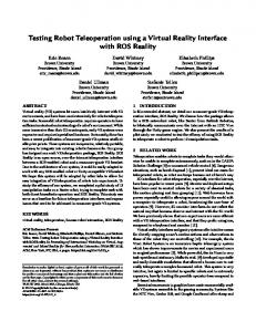
Teleoperation is a robotics technology that allows human operators to develop tasks in remote environments [16]. Usually teleoperation is used in dangerous or inaccessible environments for the operator. A teleoperation system consists of five main elements: the human operator, the master, the communication channel, the slave, and the environment (Figure 1, up). The visual information about the remote environment is feedback to the operator. Habitually the contact force of the slave with the environment is reflected to the operator to improve the task performance. In this case, the teleoperator is bilaterally controlled [9]. Virtual reality is a combination of technologies that offers natural interactions with a simulated world created by a computer. In many occasions it is applied to training applications or entertainment activities. This technology also is used in teleoperation to facilitate the operator tasks [5]. In this work it is proposed to use the virtual reality in teleoperation systems considering a virtual world where the dynamic of the objects and the robot is considered. This consideration adds interesting characteristics to teleoperation systems. To get a dynamic robot useful for teleoperation is necessary to identify the parameters of the real robot. First the dynamic teleoperation system is presented. Then the dynamic simulation of a 7 dof robot in a virtual environment is treated explaining the method used for identifying the robot parameters. Finally the results of the robot identification are showed.
2
Dynamic Teleoperation System
In a teleoperation system the operator order tasks in a remote environment from a local site. For this reason is extremely important to get a precise information of the situations generated in this remote environment. The operator in the local site needs not only accurate information about the remote site but real time information about the working scene. Unfortunately in many occasions it is impossible to get real time information of this environment due to multiple causes: large amount of information to transmit from remote to local site; heavy traffic in the network; etc [11]. If the tasks carried out by the operator consist of manipulating static objects or working in static environments, the operator could supervise the actions through the information received from the remote site and so to interact with the working scene. However, time delays in communication need to be considered. To improve the performance of the tasks made by the operator a virtual world could be considered to allow the operator to have a better knowledge of the remote environment. Virtual reality is a high-end humancomputer interface allowing user interaction with simulated environments. In teleoperation the operator closes the feedback loop with the remote robot and the real environment. If a virtual environment is considered, the operator closes the feedback loop with a virtual world (Figure 1, down).
COMPUTER
CAMERAS
SLAVE OPERATOR
REMOTE ENVIRONMENT
MASTER
COMPUTER
VIRTUAL WORLD
VIRTUAL SLAVE OPERATOR
- Collision detection - Virtual forces - Dynamic simulations
VIRTUAL ENVIRONMENT
MASTER
Fig. 1. Real teleoperation (up) versus virtual teleoperation (down).
If the tasks involve mobile objects and dynamic remote environments, the manage of this working scene could result very difficult. Mobile objects can interact with other objects in the scene modifying its trajectories. In this situation it would be very appreciate for the operator the modelling of the remote site with a virtual environment in such a way that the operator could manage this virtual environment in the same way that would order the real environment. So, the operator could anticipate the movements of the present objects in the remote site and take them into account. In this sense the object dynamics, collision detection and contact force computation for interaction between the virtual objects need to be considered. Nowadays there are a lot of virtual reality generators that allow to model simple dynamics of moving bodies. But generally the robotic articulated mechanism representation is limited a kinematic models, where the robot end-effector is the only one point that has dynamic behavior. So in these cases the haptic feedback is limited to the interaction between the point with the environment. The incorporation of the full dynamic model of the slave robot and the remote environment in a teleoperation system supplies a lot of interesting advantages. One advantage is the capacity of collision detection between the environments objects and the robot links. Another advantage is the possibility of considering the robot dynamic before to control the real robot. In this case, for example it could be analyzed if the robot could catch a moving object in a considered velocity. 2.1
Virtual Environments for Teleoperation
Milgram reviews several approaches to develop virtual environments in teleoperated systems [13]. In a dynamic virtual reality for teleoperation, the user should feel the hardness, compliance or weight of virtual objects he is manipulating. Also the user could investigate in the dynamic consequences that an action can provoke in the real scene previous to accomplish it. To make them in a useful way the operator should interact with the virtual reality by means of a device that faithfully reproduces the dynamics effects between the objects present in the virtual scene. In the teleoperation system that we are developing we use a 6 dof Phantom master arm of SensAble Technologies. This system provides precision positioning input and high-fidelity, force-feedback output. Also, the operator should perceive the results of his operations with the virtual environment. Besides of graphical properties of every object present in the virtual scene (3D CAD models of objects), the operator should know the consequences of any interaction in this virtual scene: virtual trajectories, forces and torques in the robot when it is manipulating objects, etc. In this way the user could simulate possible effects previously to accomplish them in the remote scene, and so using this information to plan or learn about the remote environment capabilities. The virtual reality have a lot of applications in teleoperation. One application is to add artificial information to the sensorial information that is feedback from the remote environment to the operator. This application is denominated
augmented reality [2]. For example, the augmented reality could be used to produce virtual contact superficies that protect the real equipment and the remote environment. Another application is to use the virtual environments in teleoperation like training tool, because of the equipment is very expensive and its difficult to manage it. When important delays appears in the communication between the local and the remote environment in a teleoperation system (spatial and underwater applications) is necessary to use predictor displays with virtual forces generation [3]. A predictive display is a graphic tool that models and simulates the environment and the remote robot behavior of the teleoperation system. The operator interacts with the virtual environment in real time before sending the commands to real remote robot. In last years there are a lot of researches that are interested in using the virtual reality to the cooperative assistance in teleoperation [10]. 2.2
Dynamic Simulation of the Remote Environment
The dynamic simulation of the remote environment produces significant advances in a teleoperation system [4]. But it is necessary to consider some difficulties that appear to get a successful simulation environment. First an efficient collision detection algorithm must be used. It must be executed in simulation time and must produce exact collision points between the couple of polygons that interaction. A lot of people is working about these algorithms and provide free software [12]. The virtual force generation when a collision is produced depends on the collision detection and location, and the dynamic model considered [5]. The independent generalized coordinates formulation require to reformulate the motion equations or to use a penalization method of the interference. In this case the calculation of the response magnitude has an important dependence on the integration period. Finally the addition of mobil objects in the virtual environment allows getting an environment more realistic, where there are two time scales: the real and the simulated. The simulated scale depends on the integration period and the computational power. The existence of two time scales and the incorporation of the full robot dynamic model provide interesting characteristics to the simulator.
3
Dynamic Simulation of a 7 dof Robot on a Virtual Environment
As it was explained, the operator on a teleoperation system make a task controlling the robot that interacts with the remote environment in a remote way. Using virtual reality, the remote environment is replicated on a virtual environment where the operator makes the task without risks for the environment or the same equipment. To consider a virtual environment as a useful tool for
the teleoperation analysis, it is necessary that all the items on the system were modelled on the most realistic way. Among the different items that can appear on a robotic virtual world, the manipulator robot has a mayor difficulty on its modelling, due to the complexity on its dynamic behavior. On the teleoperation system is being developed, a Mitsubishi PA-10 robot has been used as real robot interacting with the environment. This redundant robot is characterized by its 7 dof and for being able to work with an open architecture, sending torques directly to the servos of the robot (Figure 2,right). To put the simulated robot on the virtual world is necessary to model its kinematics and dynamics. For the kinematics the modified Denavit-Hartenberg convention used on [6] is applied, table 1. Table 1. Denavit-Hartenberg modified parameters for Mitsubishi PA-10 robot Joint a (mm) α (rad) d (mm) θ (rad) 1 2 3 4 5 6 7
0.0 0.0 0.0 0.0 0.0 0.0 0.0
0.0 -1.5708 1.5708 -1.5708 1.5708 -1.5708 1.5708
0.315 0.0 0.450 0.0 0.500 0.0 0.08
0.0 0.0 0.0 0.0 0.0 0.0 0.0
On the other hand, for getting the dynamic model, the recursive AB (Articulated Body) algorithm has been used [15]. This algorithm is implemented on the Dynamechs, a C++ free distribution library for dynamic simulation. This library allows to simulate the dynamic behavior of tree mechanisms as the PA-10 robot and to display the forces and torques that appear during the execution of the task. These generalized forces can be feedback to the operator. Nevertheless to model correctly the dynamic of the robot is necessary to know the mass parameters of each link: – – – –
Link mass Inertia matrix Center of gravity Joint friction coefficient
For the considered robot, the mass data and the location of the center of gravity for each one of the links is provided by the manufacturer, but the inertia matrix and the joint friction is unknown. To obtain real values of these parameters, a combination of CAD techniques and virtual reality has been proposed. It exists large bibliography about identification of non-linear systems and of parameter identification of manipulator robots. [1] [14]. Nevertheless the parameter
identification of a coupled and non-linear system of 7 dof robot manipulator is extremely difficult. To identify the inertia matrix of each link of the robot, a combination of CAD techniques using the geometric and mass information given by the manufacturer has been used. First of all, a solid model of each link considering the actuator and all the mobile parts has been made. The density of each link was adapted so the mass and the center of gravity of the model fits the real mass and center of gravity of the link. Next, the modified Denavit-Hartenberg reference coordinate systems were allocated on each link and the mass moments and products of inertia associated to each coordinate reference obtained. The results are shown in table 2: Table 2. Mass parameters of the model obtained Link Mass
Inertia
Center of Gravity
1
9.78
0.110697 0.000005 0.000345 0.000005 0.084268 0.000518 0.000345 0.000518 0.054080
0.0 0.0 −0.166
2
8.41
0.177079 0.000257 0.000000 0.000257 0.018440 0.000000 0.000000 0.000000 0.173903
0.0 −0.0632 0.0
3
3.51
0.032979 0.000000 0.000002 0.000000 0.017031 0.000027 0.000002 0.000027 0.022417
0.0 0.0 −0.112
4
4.31
0.051762 −0.000577 0.000000 −0.000577 0.006329 0.000000 0.000000 0.000000 0.051407
0.0 −0.046 0.0
5
3.45
0.076687 0.000000 0.000960 0.000000 0.077392 0.000000 0.000960 0.000000 0.003233
0.0 −0.0632 0.0
6
1.46
0.012500 0.000000 0.000000 0.000000 0.001431 0.000000 0.000000 0.000000 0.012500
0.0 0.003 0.0
7
0.24
0.001575 0.000000 0.000000 0.000000 0.001575 0.000000 0.000000 0.000000 0.000131
0.0 0.0 0.0
On the other side, the same virtual simulator has been used as a tool to identify the friction coefficient of the links. A ”prove and error” technique has
been used to get the values of these parameters. The joint coordinates position values obtained by the simulator were compared with the experimental ones and the friction coefficient was modified in order to fit the values on the next simulation. Different joint trajectories have been used on the real robot, and the joint positions and torques were registered on a file; the registered torques were taken as input for the simulator robot. The most difficult task on this procedure is to synchronize the data obtained in the real robot with the simulation technique so the simulator reads the data at the correct time. To register the joint position and torques of the real robot in an ASCII format, an application using the C PA-10 library given by the manufacturer of the robot, was developed. Using the Mitsubishi library and the Microsoft Visual C++ 5.0 as developing environment, the application was run over Microsoft Windows NT 4.0. The PA-10 library has a great variety of functions to control the movement of the robot (joint position, cartesian position, position control, velocity control,...). Nevertheless, the library does not have an specific function to read the torques on each joint, and this data is essential for a fine identification of the dynamic model. But the robot is equipped with a current sensor on each actuator, and the PA-10 library has been given with the source code on C, so the torques can be calculated. A function able to read the torques on each joint was incorporated to the library. On the other side, using the dynamic simulation library Dynamechs and Microsoft Visual C++ 5.0 under Windows platform, an application that shows the robot and the virtual environment was created (Figure 2). On this application, the PA-10 model obtained was introduced. The simulator reads the torque values synchronizing the input on simulation time with the real time, and shows the trajectory of the simulated robot.
Fig. 2. Developed application for virtual dynamic robot Mitsubishi PA-10 (left) and real robot (right)
Using both applications, several experiments for the identification of the friction coefficients of each link have been made. Some of these experiments are shown next.
4
Experimental Results
To begin with, a series of experiments for the parameter identification of the friction for each joint of the robot were made. On these experiments, the only joint that had movement was the one that was being identified, meanwhile the others one were braked. So, the identification were made over an uncoupled system. This way, a ”prove and error” approximation method is made joint by joint. The values obtained are highly dependent on the input experimental data, so the model obtained is valid only over a range of joint coordinates given by the joint coordinate range used for the experimental data input. Due that the experimental data used for these experiments include acceleration and deceleration profiles given by the servocontrol of the PA-10 and that are according with the dynamics of the actuators of the robot, the range of the joint coordinates must not be so wide. Obtaining a complete valid model for the workspace of the robot implies the creation of a table containing values of the joint friction for each interval on the corresponding joint coordinate, so that the model adapts itself to the non-linear and coupled behavior of the real system. Figure 3 shows the obtained results for the movement of each joint over a bigger interval of joint variables once the friction parameter has been adjusted. On last joints, the behavior of the simulator corresponds with the experimental data of the real robot, and the trajectories have similar values over the whole range. Nevertheless, in the first joints, exception on the S1 (the base revolute), the differences are higher, due to the limited number of adjusting parameters used on this model, only one for joint, and the non-linear and coupled behavior of the robot. Besides, the peak of the starting torque of the motors is higher on the first links, and this fact implies a faster acceleration on the real robot than on the simulated, because the simulated is limited on this output by the numerical integration step used. With the obtained values on the experiments, a coupled all joints movement of the real robot was simulated. All the articulations were increased on a small value and with small velocity, and the model obtained was tested with good results over a range of variation of joint coordinates near the values used for the identification of the friction parameters.
5
Conclusions
In this paper it has been showed new characteristics that the virtual reality adds to teleoperation. It has been modelled a virtual environment where the dynamic of the objects and the robot is contemplated. This consideration permits to analyze the dynamic of the virtual robot before to control the real robot. To get a virtual environment useful for teleoperation tasks is necessary to utilize collision detection and virtual force generation efficient algorithms. Also it is very important to use a dynamic engine that allows to simulate the behavior of the robot and the objects efficiently. In this work it has been presented how to use the virtual reality to get the slave robot dynamic model of the teleoperation system. It could be observed
PA-10 Virtual Robot Torques
Fig. 3. Results of the movement of each joint
that the identified robot model is similar to the real robot if a determined work area is considered. Nowadays more experiments are in development to get the dynamic model robot for the full work environment.
Acknowledgements This work has been supported by the Spanish Government inside the Plan Nacional de Investigacion Cientifica, Desarrollo e Innovacion Tecnologica 2000-2003 through project DPI2001-3827-C02-02.
References 1. Antonelli, G., Caccavale, F., Chiacchio, P.: A Systematic Procedure for the Identification of Dynamic Parameters of Robot Manipulators. Robotica, Vol. 17 (1999), 427 - 435. 2. Azuma, R.T.: A Survey on Augmented Reality. Presence, Vol. 11, No. 2, April 1992. 3. Bejczy, A.K., Kim, W.S., Venema, S.: The Phantom Robot: Predictive Displays for Teleoperation with Time Delay. IEEE International Conference on Robotics and Automation, (1990), 546 - 551. 4. Burdea, G.C.: The Synergy Between Virtual Reality and Robotics. IEEE Transactions on Robotics and Automation, Vol. 15, No. 3. (1999) 400–411 5. Burdea, G.C.: Force and Touch Feedback for Virtual Reality. John Wiley & Sons, Inc. USA. 1996. 6. Craig, John.: Introductions to Robotics, mechanics and control, Second Edition. Addison-Wesley Publishing Company 1989. 7. Dupont, P.E., Shulteis, T.M., Millman, P.A., Howe, R.D.: Automatic Identification of Environment Haptic Properties. Presence: Teleoperators and Virtual Environments, (1999) 8. Dupont, P.E., Schulteis, T.M., Howe, R.D.,: Experimental Identification of Kinematic Constraints. Proceedings of the IEEE International Conference on Robotics and Automation, Albuquerque, New Mexico (1997) 2677–2682 9. Hannaford, B.: Stability and Performance Tradeoffs in Bi-lateral Telemanipulation.IEEE International Conference on Robotics and Automation (1989), 1764-1767. 10. Heguy, O., Rodriguez, N., Luga, H., Jessel, J.P., Duthen, Y.: Virtual Environment for Cooperative Assistance in Teleoperation. 9th International Conference in Central Europe on Computer Graphics, Visualization and Computer Vision 2001, Plzen, Czech Republic. 11. Kawabata, K., Sekine, T., Suzuki, T., Fujii, T., Asama, H., Endo, I.,: Mobile Robot Teleoperation System Utilizing a Virtual World. Advanced Robotics, Vol. 15, No. 1. (2001) 1–16 12. Lin, M.C.:Efficient Collision Detectioni for Animation and Robotics. PhD thesis, Department of Electrical Engineering and Computer Science, University of California, Berkeley, December 1993. 13. Milgram, P., Ballantyne, J.,: Real World Teleoperation via Virtual Environment Modelling. Proc. International Conference on Artificial Reality and Tele-existence ICAT’97, Tokyo (1997) 1–9 14. Schmidt, C., Prfer, M.: Parameter Identification in Robot Control. International Journal of Applied Mathematics and Computer Science, Vol. 7 (1997), No. 2, 377 399. 15. Scott McMillan: Computational Dynamichs for Robotic System on Lands and Under Water. Dissertation. The Ohio State University, 1995. 16. Vertut, J., Coiffet, P.: Teleoperation and Robotics. Evolution and Development. Kopan Page. London. 1985.