A hardboard and wood viewing tunnel 57 ern long x 60 em wide x 35 cm high enclosed the entire foreground area. The oscillo- scope was positioned at one end ...
Perception & Psychophysics
1992, 52 (4). 446-452
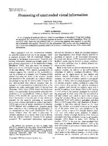
Visual and nonvisual information disambiguate surfaces specified by motion parallax SHEENA ROGERS and BRIAN J. ROGERS University of Oxford, Oxford, England Motion parallax has been shown to be an effective and unambiguous source of information about the structure of three-dimensional (3-D) surfaces, both when an observer makes lateral movements with respect to a stationary surface and when the surface translates with respect to a stationary observer (Rogers & Graham, 1979). When the same pattern of relative motions among parts of the simulated surface is presented to a stationary observer on an unmoving monitor, the perceived corrugations are unstable with respect to the direction of the peaks and troughs. The lack of ambiguity in the original demonstrations could be due to the presence of (1) non-visual information (proprioceptive and vestibular signals) produced when the observer moves or tracks a moving surface, and/or (2) additional optic flow information available in the whole array. To distinguish between these two possibilities, we measured perceived ambiguity in simulated 3-D surfaces in situations where either nonvisual information or one of four kinds of visual information was present. Both visual and nonvisual information were effective in disambiguating the direction of depth within the simulated surface. Real perspective shape transformations affecting the elements of the display were most effective in disambiguating the display. Motion parallax has been shown to be an effective and unambiguous source of information about the structure of three-dimensional (3-D) surfaces (Rogers & Graham, 1979). With the use of a technique analogous to the random-dot stereograms devised by Julesz (1960, 1971), motion parallax can be studied in isolation from other possible sources of information (such as occlusion) that normally occur when we move. This technique has provided convincing evidence that motion parallax can supply sufficient information for the perception of depth, shape, and relative position of surfaces in depth (Rogers & Graham, 1979, 1982, 1983; Graham & Rogers, 1982). The displays simulate a corrugated surface in the frontoparallel plane under parallel projection. Perception is consistent and unambiguous both when an observer makes lateral movements with respect to a stationary surface and when the surface translates with respect to a stationary observer (Rogers & Graham, 1979). When the same pattern of relative motions among parts of the simulated surface is presented to a stationary observer on an unmoving monitor, the perceived direction, or sign, of the peaks and troughs of the surface is unstable and reversible. Figure 1 shows the relative displacement of random dots in a display simulating a square-wave corrugation similar to those used by Rogers and Graham (1979). Alternate bands of dots move in opposite directions but at We would like to thank Hiroshi Ono for helpful discussions during the early stages of this research. Correspondence concerning this article should be addressed to Sheena Rogers, who is now with the Department of Psychology, University of Wisconsin-Madison, 1202 West Johnson Street, Madison, WI 53706.
Copyright 1992 Psychonornic Society, Inc.
the same velocity. The center band could equally be behind the surround or in front of it, yet in Rogers and Graham's experiment, the order of the surfaces in depth was reported consistently on every trial. This ambiguity is similar to that found in parallel projections, and, in fact, earlier studies reported poor perception of threedimensionality for a parallel projection of a translating surface and the expected ambiguity of perceived depth order in parallel projections of rotating surfaces (Braunstein, 1966; Wallach & O'Connell, 1953). The absence of perceived ambiguity in Rogers and Graham's (1979) study therefore needs to be explained. Motion parallax is not inherently ambiguous. More commonly, motion parallax displays use polar projection and present elements moving in the same direction but at different velocities. The angular velocity of parts of a surface or of separate objects in the visual field is inversely proportional to their distance away from the observer. Theoretically, the faster moving elements would be nearer to the observer and the surface should appear rigid, stable, and unambiguous, even in the absence of observer or monitor motion. Early studies were only partially successful at demonstrating that observers do in fact see the depth order predicted from differences in angular velocity (e.g., Gibson, Gibson, Smith, & Flock, 1959). More recently, researchers have managed to obtain correct judgments on over 90% of trials under certain conditions (e.g., Braunstein & Andersen, 1981; Braunstein & Tittle, 1988). Given the theoretical ambiguity of the motion field within Rogers and Graham's (1979) displays, some additional factor (or factors) is clearly providing information
446
DISAMBIGUATING MOTION PARALLAX
447
A second possibility is that additional visual information was available to observers in the Rogers and Graham (1979) experimental paradigm. In both the self-produced and the externally produced parallax conditions, there was an ambiguous pattern of equal and opposite relative motions among the elements of the display itself, defined relative to the monitor. The experiments were not carried out in a completely darkened room, however, and b thus the subject could see the frame of the oscilloscope, the layout of the apparatus, and other objects in the room. The dots on the screen also moved in relation to these other objects in the laboratory and in relation to the observer. The complete flow field, or optic array, defined Figure 1. The figure shows (a) the 3-D surface, and (b) the relarelatively to the observer, is potentially quite different tive displacement of random dots that would be produced by movfrom the monitor-relative velocity field. When this coming the bead from left to right. At first, the center band of dots is plete observer-relative flow field is considered, additional displaced to the right witb respect to the surround, but as the head sources of visual information are available: (I) projective is moved to the right, the band of dots is progressively displaced (trapezoidal) changes in the overall shape of the dot patto the left. Note that in the actual display, the random dots always completely filled the screen behind a circular aperture so that the tern, and (2) the pattern of relative motions that exist edges of the distorting pattern, whicb could provide additional inbetween the elements of the display and features of the formation, were not visible. foreground and surrounding surfaces. Braunstein and Tittle (1988) have identified a third for the depth order of the surfaces. In earlier experiments, potential source of visual information in the observerperceptual ambiguity with similar displays had been found relative array that could disambiguate the depth order of with the use of both stationary observers and stationary the display. The bands of the display move in opposite displays. Thus it would seem that for motion parallax in- directions and at equal velocity only when their motion formation with equal and opposite velocities to be con- is defined relative to the monitor. However, in Rogers sistent and unambiguous, additional information produced and Graham's (1979) experiment, either the observer or either by the movement of the observer's head, or by the the monitor was also moving, and so there is an additional movement of the display relative to the observer's head, common motion component, from the movement of the is required. The present experiment was an attempt to head or of the oscilloscope, to be added to the velocity identify the source of this disambiguating information by field within the display itself. The effect of this is to insystematically controlling potential contributing factors. crease the angular velocity (within the observer-relative The absence of ambiguity in Rogers and Graham's origi- flow field) of the band moving in the same direction as nal motion parallax displays could have been due to the the scope, or in the direction opposite that of the observer, presence of either (I) nonvisual information produced and to decrease that of the band moving in the other direcwhen the observer or surface moved, or (2) additional tion in each case. The resulting flow field no longer has optic flow information from the entire array, including equal and opposite relative motions. All parts of the surobjects surrounding the simulated 3-D surfaces. In the face now move in the same direction but at different vepresent experiment, we examined these alternatives by locities. This flow field is theoretically unambiguous and Braunstein and Tittle's (1988) results indicate that the vecomparing six different display and viewing conditions. Potential sources of disambiguating information were locity field is, indeed, able to govern perceived order in systematically isolated and tested for their ability to bias depth. perceived direction of depth. It is important to separate these different sources of It is possible that the self-produced parallax condition visual information in the observer-relative optic array. In (with head movement) provides important nonvisual in- particular, the observer-relative velocity field should reformation, in the form of proprioceptive and vestibular main ambiguous throughout the observation period so that signals, that is utilized by the visual system in disambiguat- one can examine the contribution of (I) the overall shape ing the direction of depth in the simulated surface. (In changes in the display and (2) the pattern of relative mothe externally produced parallax condition, such informa- tion~.~tween the display and the foreground. This contion may also be available from the tracking movements sideration entailed an important change in the original of the eyes and head required during observation of the Rogers and Graham (1979) procedure. In a pure translamoving oscilloscope display.) Isolating this nonvisual in- tion (of display or observer), all three of the above visual formation allows one to test whether it is sufficient to de- information sources necessarily covary in a natural scene. termine a consistent perceived depth order in a visually To allow the overall projective shape of the display to vary ambiguous display. If it is, we would expect that the band independently of the velocity field (maintaining the amof dots moving in a direction opposite that of the observer biguous, equal, and opposite pattern), it was necessary will appear nearer than the band moving in the same to rotate the display about a point underneath the center direction. of the screen in one condition of the present experiment.
a
448
ROGERS AND ROGERS
The dot motions on the screen were still translations, but the observer-relative velocity field still consisted of equal velocity motions in opposite directions. Rogers and Graham's procedure actually involved both a large horizontal translation component and a rotation component: In the self-produced parallax condition, the chinrest rotated about a point under the screen, and the head followed a shallow arc path. In the externally produced parallax condition, the oscilloscope pivoted about a point at the back of the scope, and the screen followed a similar shallow arc path. Disambiguation of surface depth order in the present study is therefore highly relevant to the earlier study. Full descriptions of each of the six display and viewing conditions of the present experiment are given below, along with specific predictions for each condition.
METHOD Displays and Apparatus The motion parallax displays were generated by the same general method and with similar apparatus as Rogers and Graham's earlier study, described in detail there and elsewhere (Rogers & Graham, 1979, 1982; Graham & Rogers, 1982). A computergenerated random-dot pattern was displayed and transformed in real time, exactly simulating the relative displacements among parts of the display that would be produced in the flow field by a real corrugated surface as the observer's head moved from side to side. The pattern was displayed on a large-screen oscilloscope (HP 1304A) positioned 57 em from the subject's eye. The screen subtended 20° (vertically) X 25° (horizontally) of visual angle, but only a circular area subtending 17° was visible to the observer. The pattern was made up from an array of 256 x 256 points, each of which could be illuminated with a 50% probability. The pattern was generated on a Matrox ALT 256 graphics board interfaced to a Cromenco System 3 computer. All displays simulated a sine-wave corrugation with three complete cycles from top to bottom. The spatial frequency of the 3-D surface was therefore 0.15 cycles per degree (cpd). Maximum relative dot displacement was 50.4 arc min, equivalent to 3.02 cm of relative depth from the peaks to the troughs of the corrugations. (Note that Rogers & Graham, 1979, used a smaller screen oscilloscope subtending 12.5° x 10° of visual angle with a 64x64 array of points. They set the spatial frequency of the corrugations at O.I, 0.3, or 0.5 cpd and varied the amplitude of the modulating signal, giving simulated depths from 0.66 to 3.02 cm.) A system of turntables was constructed to allow independent control of the movement of the oscilloscope and of the foreground. A hardboard and wood viewing tunnel 57 ern long x 60 em wide x 35 cm high enclosed the entire foreground area. The oscilloscope was positioned at one end of the tunnel, and a chinrest was fixed to the other end. The tunnel was lined with black card in all except the foreground flow condition, when it was lined with black and white irregularly patterned paper. Either the oscilloscope and the tunnel rested on separate platforms, each of which was 57 ern long x 60 em wide, or both objects were placed on one longer platform 114 ern long x 60 ern wide. The platforms could be rotated to and fro through 15° , pivoting about a point under the center of the oscilloscope screen. The oscilloscope could be raised very slightly and held on metal rods to allow the long platform to be rotated while the oscilloscope itself remained stationary. A circular aperture cut in stiff black card was positioned just in front of the screen and fixed either to the tunnel or to the scope so that it remained stationary during scope or tunnel movement, respectively.
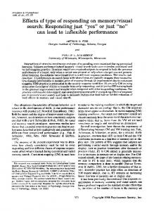
A heavy black card frame 36 cm high x 90 ern wide surrounded the oscilloscope screen, preventing the observer from seeing any part of the apparatus or the room beyond the display during the experiment. Viewing was monocular. The random-dot pattern was still, appearing to be 2-D and without structure until either the oscilloscope or the foreground tunnel moved. A potentiometer under the platform monitored its movement. A voltage derived from the potentiometer modulated a sine-wave signal from a Wavetek 175 arbitrary waveform generator that was fed to the .r-input of the oscilloscope, systematically distorting the random-dot pattern. In the control condition and in conditions with simulated trapezoidal shape transformations, the deforming signal was supplied by a generator and did not depend on movement of the apparatus. Viewing Conditions There were six different viewing conditions: the first was a control condition in which perceived ambiguity was predicted; in the second, nonvisual information for self-motion was isolated; in the third, fourth, and fifth, aspects of overall projective shape changes were respectively examined; and the sixth included a pattern of relative motion in the foreground, between the display and the observer. The essential features of each of these conditions of the experiment are illustrated in Figure 2 (panels a-f). The walls and ceiling of the tunnel are not shown in the figure. The edges of the display always extended beyond the circular aperture and were not visible. Control condition (Figure 2a). Neither the observer nor the oscilloscope moved, and no other potential source of information was available that could be expected to disambiguate the display. Here, and in all except the foreground flow condition, the entire visible foreground (inside the tunnel) was black and viewing was in dim light to minimize additional optic flow information. Nonvisual information (Figure 2b). Vestibular and proprioceptive information for egomotion were isolated, and visual information from the surrounding surfaces was controlled. No additional visual information was available to help disambiguate the depth order of parts of the simulated surface. The scope and tunnel were mounted on the long platform, which rotated to and fro with the side-to-side movements of the observer's head. The observer's head was securely held in a chinrest attached to the tunnel. The tunnel was gripped at the sides by the subject, who then moved the entire apparatus smoothly to and fro, making one complete oscillation about every 2 sec. The entire array was therefore stationary in relation to the observer, except that the sinusoidal displacement of the pattern of dots within the display was yoked to the movement of the apparatus. If the direction of depth in the surface is perceived consistently here, it follows that vestibular and proprioceptive information can disambiguate motion parallax. When a frontoparallel, rectangular, planar surface (such as the screen of an oscilloscope) translates or rotates with respect to an observer, the surface projects to a trapezoid in the flow field. This shape change also affects the markings on the surface, and it has three principal components: (1) a linear perspective component in which horizontal lines of elements converge in the array with increasing distance from the observer (since these changes occur along the vertical dimension of the flow field, this component has been called vertical perspective; Braunstein, 1977); (2) a gradient of increasing texture density as the surface recedes, and (3) a horizontal width change. These last two can be called horizontal perspective. Three separate display conditions were employed to investigate the contribution of these projective shape changes. Real perspective information (trapezoidal shape changes) (Figure 2c). The combined effects of normal perspective were separated from other visual and nonvisual factors. This was achieved without head movement and without oscilloscope translation (and
DISAMBIGUATING MOTION PARALLAX
I.-
....l>
~