Prior research [17, 19] has shown that heterogeneous ... ond, they enable us to design the processor with compact, .... order buffer, register file, load/store queue, and instruction .... dividual partitions of the ROB/RF, we simply assume that ..... is changed, for 2-thread and 4-thread workloads (medium-end cores). 0. 20. 40. 60.
Published in 18th International Symposium on High Performance Computer Architecture, February, 2012
Dynamically Heterogeneous Cores Through 3D Resource Pooling Houman Homayoun
Vasileios Kontorinis
Amirali Shayan
Ta-Wei Lin
Dean M. Tullsen
University of California San Diego Abstract This paper describes an architecture for a dynamically heterogeneous processor architecture leveraging 3D stacking technology. Unlike prior work in the 2D plane, the extra dimension makes it possible to share resources at a fine granularity between vertically stacked cores. As a result, each core can grow or shrink resources, as needed by the code running on the core. This architecture, therefore, enables runtime customization of cores at a fine granularity and enables efficient execution at both high and low levels of thread parallelism. This architecture achieves performance gains from 941%, depending on the number of executing threads, and gains significant advantage in energy efficiency of up to 43%.
1. Introduction Prior research [17, 19] has shown that heterogeneous multicore architectures provide significant advantages in enabling energy-efficient or area-efficient computing. It allows each thread to run on a core that matches its resource needs more closely than a single one-size-fits-all core. However, that approach still constrains the ability to optimally map executing threads to cores because it relies on static heterogeneity, fixed at design time. Other research attempts to provide dynamic heterogeneity, but each face a fundamental problem. Either the pipeline is tightly constructed and the resources we might want to share are too far away to be effectively shared, or the shared resources are clustered and the pipeline is inefficient. As a result, most provide resource sharing or aggregation at a very coarse granularity – Core Fusion [13] and TFlex [16] allow architects to double or quadruple the size of cores, for example, but do not allow a core to borrow renaming registers from another core if that is all that is needed to accelerate execution. Thus, the heterogeneity is constrained to narrow cores or wide cores, and does not allow customization to the specific needs of the running thread. The WiDGET architecture [36] can only share execution units, and thus enables only modest pipeline inflation. The conjoined core architecture [18] shares resources between adjacent cores,
but sharing is limited by the topology of the core design to only those structures around the periphery of the pipeline. This work demonstrates that 3D stacked processor architectures eliminate the fundamental barrier to dynamic heterogeneity. Because of the extra design dimension, we can design a tight, optimized pipeline, yet still cluster, or pool, resources we might like to share between multiple cores. 3D die stacking makes it possible to create chip multiprocessors using multiple layers of active silicon bonded with low-latency, high-bandwidth, and very dense vertical interconnects. 3D die stacking technology provides very fast communication, as low as a few picoseconds [21], between processing elements residing on different layers of the chip. Tightly integrating dies in the third dimension has already been shown to have several advantages. First, it enables the integration of heterogeneous components such as logic and DRAM memory [21], or analog and digital circuits [21], fabricated in different technologies (for instance integration of a 65nm and a 130nm design). Second, it increases the routability [28]. Third, it substantially reduces wire length, which translates to lowered communication latency and reduced power consumption [21, 23, 28]. The dynamically heterogeneous 3D processors we propose in this paper provide several key benefits. First, they enable software to run on hardware optimized for the execution characteristics of the running code, even for software the original processor designers did not envision. Second, they enable us to design the processor with compact, lightweight cores without significantly sacrificing generalpurpose performance. Modern cores are typically highly over-provisioned [18] to guarantee good general-purpose performance – if we have the ability to borrow the specific resources a thread needs, the basic core need not be overprovisioned in any dimension. Third, the processor provides true general-purpose performance, not only adapting to the needs of a variety of applications, but also to both high thread-level parallelism (enabling many area-efficient cores) and low thread-level parallelism (enabling one or a few heavyweight cores). With a 3D architecture, we can dynamically pool resources that are potential performance bottlenecks for possible sharing with neighboring cores. The StageNet architecture [7] attempts to pool pipeline stage resources for re-
liability advantages. In that case, the limits of 2D layout mean that by pooling resources, the pipeline must be laid out inefficiently, resulting in very large increases in pipeline depth. Even Core Fusion experiences significant increases in pipeline depth due to communication delays in the front of the pipeline. With 3D integration, we can design the pipeline traditionally in the 2D plane, yet have poolable resources (registers, instruction queue, reorder buffer, cache space, load and store queues, etc.) connected along the third dimension on other layers. In this way, one core can borrow resources from another core or cores, possibly also giving up non-bottleneck resources the other cores need. This paper focuses on the sharing of instruction window resources. This architecture raises a number of performance, energy, thermal, design, and resource allocation issues. This paper represents a first attempt to begin to understand the various options and trade-offs. This paper is organized as follows. Section 2 describes our 3D architecture assumptions, both for the baseline multicore and our dynamically heterogeneous architecture. Section 3 shows that both medium-end and high-end cores have applications that benefit from increased resources, motivating the architecture. Section 4 details the specific circuits that enable resource pooling. Section 5 describes our runtime hardware reallocation policies. Section 6 describes our experimental methodology, including our 3D models. Section 7 gives our performance, fairness, temperature, and energy results. Section 8 describes related work.
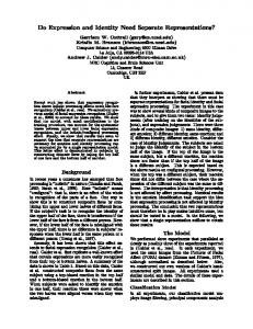
2. Baseline Architecture In this section, we discuss the baseline chip multiprocessor architecture and derive a reasonable floorplan for the 3D CMP. This floorplan is the basis for our power/temperature/area and performance modeling of various on-chip structures and the processor as a whole. 3D technology, and its implications on processor architecture, is still in the early stages of development. A number of design approaches are possible and many have been proposed, from alternating cores and memory/cache [20, 23], to folding a single pipeline across layers [27]. In this research, we provide a new alternative to the 3D design space. A principal advantage of the dynamically heterogeneous 3D architecture is that it does not change the fundamental pipeline design of 2D architectures, yet still exploits the 3D technology to provide greater energy proportionality and core customization. In fact, the same single design could be used in 1-, 2-, and 4-layer configurations, for example, providing different total core counts and different levels of customization and resource pooling. For comparison purposes, we will compare against a commonly proposed approach which preserves the 2D pipeline design, but where core layers enable more extensive cache and memory.
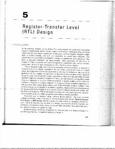
Figure 1. CMP configurations: (a) baseline and (b) resource pooling.
2.1. Processor Model We study the impact of resource pooling in a quad-core CMP architecture. This does not reflect the limit of cores we expect on future multicore architectures, but a reasonable limit on 3D integration. For example, a design with eight cores per layer and four layers of cores would provide 32 cores, but only clusters of four cores would be tightly integrated vertically. Our focus is only on the tightly integrated vertical cores. For the choice of core we study two types of architecture, a high-end architecture which is an aggressive superscalar core with issue width of 4, and a medium-end architecture which is an out-of-order core with issue width of 2. For the high-end architecture we model a core similar to the Alpha 21264 (similar in functionality to the Intel Nehalem Core, but we have more data available for validation on the 21264). For the medium-end architecture we configure core resources similar to the IBM PowerPC-750 FX processor [12].
2.2. 3D Floorplans The high-level floorplan of our 3D quad-core CMP is shown in Figure 1. For our high-end processor we assume the same floorplan and same area as the Alpha 21264 [15] but scaled down to 45nm technology. For the mediumend architecture we scale down the Alpha 21264 floorplan (in 45nm) based on smaller components in many dimensions, with area scaling models similar to those described by Burns and Gaudiot [3]. Moving from 2D to 3D increases power density due to the proximity of the active layers. As a result, temperature is always a concern for 3D designs. Temperature-aware floorplanning has been an active topic of research in the literature. There have been a number of 3D CMP temperatureaware floorplans proposed [5, 8, 26]. Early work in 3D architectures assumed that the best designs sought to alternate hot active logic layers with cooler cache/memory layers.
More recent work contradicts that assumption – it is more important to put the active logic layers as close as possible to the heat sink [39]. Therefore, an architecture that clusters active processor core layers tightly is consistent with this approach. Other research has also exploited this principle. Loh, et al. [21] and Intel [1] have shown how stacking logic on logic in a 3D integration could improve the area footprint of the chip, while minimizing the clock network delay and eliminating many pipeline stages. For the rest of this work we focus on the two types of floorplan shown in Figure 1(a) and Figure 1(b). Both preserve the traditional 2D pipeline, but each provides a different performance, flexibility, and temperature tradeoff. The thermal-aware architecture in Figure 1(a) keeps the pipeline logic closest to the heat-sink and does not stack pipeline logic on top of pipeline logic. Conversely, the 3D dynamically heterogeneous configuration in Figure 1(b) stacks pipeline logic on top of pipeline logic, as in other performance-aware designs, gaining increased processor flexibility through resource pooling. Notice that this comparison puts our architecture in the worst possible light – for example, a many-core architecture that already had multiple layers of cores would have very similar thermal characteristics to our architecture without the benefits of pooling. By comparing with a single layer of cores, the baseline has the dual advantages of not having logic on top of logic, but also putting all cores next to the heat sink.
3. Resource Pooling in the Third Dimension Dynamically scheduled processors provide various buffering structures that allow instructions to bypass older instructions stalled due to operand dependences. These include the instruction queue, reorder buffer, load-store queue, and renaming registers. Collectively, these resources define the instruction scheduling window. Larger windows allow the processor to more aggressively search for instruction level parallelism. The focus of this work, then, is on resource adaptation in four major delay and performance-critical units – the reorder buffer, register file, load/store queue, and instruction queue. By pooling just these resources, we create an architecture where an application’s scheduling window can grow to meet its runtime demands, potentially benefiting from other applications that do not need large windows. While there are a variety of resources that could be pooled and traded between cores (including execution units, cache banks, etc.), we focus in this initial study of dynamically heterogeneous 3D architectures on specific circuit techniques that enable us to pool these structures, and dynamically grow and shrink the allocation to specific cores. In this section, we study the impact on performance of increasing the size of selected resources in a 3D design. We assume 4 cores are stacked on top of each other. The max-
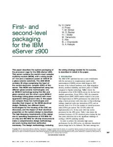
imum gains will be achieved when one, two, or three cores in our 4-core CMP are idle, freeing all of their poolable resources for possible use by running cores. The one-thread case represents a limit study for how much can be gained by pooling, but also represents a very important scenario – the ability to automatically configure a more powerful core when thread level parallelism is low. This does not represent an unrealistic case for this architecture – in a 2D architecture, the cost of quadrupling, say, the register file is high, lengthening wires significantly and moving other key function blocks further away from each other. In this architecture, we are exploiting resources that are already there, the additional wire lengths are much smaller than in the 2D case, and we do not perturb the 2D pipeline layout. We examine two baseline architectures (details given in Section 6) — a 4-issue high-end core and a 2-issue mediumend core. In Figure 2 we report the speedup for each of these core types when selected resources are doubled, tripled, and quadrupled (when 1, 2, and 3 cores are idle). Across most of the benchmarks a noticeable performance gain is observed with pooling. Omnetpp shows the largest performance benefit in medium-end cores. The largest performance is observed in swim and libquantum for high-end cores. Performance gains are seen with increased resources, but the marginal gains do drop off with larger structures. Further experiments (not shown) indicate that pooling beyond four cores provides little gain. The more scheduling resources we provide, the more likely it is that some other resource (e.g., the functional units, issue rate, cache) that we are not increasing becomes the bottleneck. In fact, this is true for some benchmarks right away, such as mcf and perlbench, where no significant gains are achieved, implying some other bottleneck (e.g., memory latency) restricts throughput. On average, 13 to 26% performance improvement can be achieved for the medium-end processor, and 21 to 45% for the high end, by increasing selected window resources. Most importantly, the effect of increased window size varies dramatically by application. This motivates resource pooling, where we can hope to achieve high overall speedup by allocating window resources where they are most beneficial.
4. Stackable Structures for Resource Pooling
This section describes the circuit and architectural modifications required to allow resources on vertically adjacent cores to participate in pooling. Specifically, we describe the changes required in each of the pipeline components.
4.1. Reorder Buffer and Register File The reorder buffer (ROB) and the physical register file (RF) are multi-ported structures typically designed as SRAM, with the number of ports scaling with the issue width of the core. Our goal is to share them across multiple cores with minimal impact on access latency, the number of
(a)
(b) Figure 2. Speedup from increasing resource size in the 3D stacked CMP with (a) medium-end and (b) high-end cores.
ports, and the overall design. We take advantage of a modular ROB (and register file) design proposed in [25] which is shown to be effective in reducing the power and complexity of a multi-ported 2D SRAM structure. Our baseline multi-ported ROB/RF is implemented as a number of independent partitions. Each partition is a self-standing and independently usable unit, with a precharge unit, sense amps, and input/output drivers. Partitions are combined together to implement a larger ROB/RF, as shown in Figure 3(a). The connections running across the entries within a partition (such as the bit-lines) are connected to a common through line using bypass switches. To add a partition to the ROB/RF, the bypass switch for a partition is turned on. Similarly, the partition can be deallocated by turning off the corresponding bypass switch. The modular baseline architecture of our register file allows individual partitions to participate in resource pooling. To avoid increasing the number of read and write ports of individual partitions of the ROB/RF, we simply assume that an entire partition is always exclusively owned by one core — either the core (layer) it belongs to (host core) or another core (guest core). This significantly simplifies the design, but restricts the granularity of sharing. Note that before a partition participates in resource pooling (or before it is re-assigned) we need to make sure that all of its entries are empty. This can be facilitated by using an additional bit in each row (entry) of the partition to indicate whether it is full or empty – in most cases, that bit will already exist. Figure 3(b) shows a logical view of two stacked register
files, participating in resource pooling (only one partition of the RF from each layer is shown in this figure). The additional multiplexers and decoder shown in Figure 3(b) are used to route the address and data from/to a partition in one layer from/to another partition in a different layer. The decoder shown in the figure enables stacking of the ROB/RF. To be able to pool up to 4 ROB/RF partitions on four different layers together, we need to use a 4-1 decoder and a 4-1 multiplexer. The register operand tag is also extended with 2 additional bits. The overall delay added to the ROB or RF due to additional multiplexing and decoding is fairly small. For the case of stacking four cores where a 4 input decoder/multiplexer is needed, the additional delay is found to be below 20 ps (using SPICE simulation and assuming a standard cell 4 input multiplexer). In this design, the access latency of the original register file is only 280ps (using CACTI for an 8 read-port, 4 write-port, 64 entry register file). The additional 20 ps delay due to an additional decoder/multiplexer and the TSVs (5ps at most) still keep the overall delay below one processor cycle. Thus, the frequency is not impacted. For the ROB, the baseline delay is 230 ps and the additional delay can still be tolerated, given our baseline architectural assumptions. Due to the circular FIFO nature of the ROB, an additional design consideration to implement resource sharing is required, which is not needed for the register file. The ROB can be logically viewed as a circular FIFO with head and tail pointers. The tail pointer points to the beginning of the free entry of the ROB where new dispatch instructions can be allocated. The instructions are committed from the head
Throughline
memory cell array bitline
sense-amps input/output drivers
Bypass switch
bypass switch array
memory cell array sense-amps input/output drivers bypass switch array
(a)
(b)
Figure 3. (a) Partitioned ROB and RF design, (b) logical view of two stacked RF(ROB) partitions.
pointer. Resource sharing requires dynamically adjusting the size of the reorder buffer. To implement such dynamic resizing we use the technique proposed in [25], where two additional pointers are added to the ROB to dynamically adjust its size.
4.2. Instruction Queue and Ld/St Queue
Both the Instruction Queue (IQ) and the Load/Store Queue (LSQ) are CAM+SRAM structures which hold instructions until they can be issued. The main complexity of the IQ and LSQ stems from the associative search during the wakeup process [24]. Due to large power dissipation and large operation delay, the size of these units does not scale well in a 2D design. The number of instruction queue and LSQ entries has not changed significantly in recent generations of 2D processors. Figure 4(a) shows a conventional implementation of the instruction queue. The taglines run across the queue and every cycle the matchline compares the tagline value broadcast by the functional units with the instruction queue entry (source operand). We assume our baseline IQ utilizes the well-studied divided tagline (bitline) technique [14]. As shown in Figure 4(b), two or more IQ entries are combined together to form a partition and to divide the global tag line into several sub-tag lines. This way the IQ is divided into multiple partitions. In the non-divided tag line structure the tag line capacitance is N * diffusion capacitance of pass transistors + wire capacitance (usually 10 to 20% of total diffusion capacitance) where N is the total number of rows. In the divided tag line scheme the equivalent tagline capacitance is greatly reduced and is approximated as M * diffusion capacitance + 2 * wire capacitance, where M is the number of tagline segments. As tagline dynamic power dissipation is proportional to CV 2 , reducing the effective capacitance will linearly reduce tagline dynamic power. The overhead of this technique is adding a set of pass transis-
tors per sub-tagline. As a side effect, the large number of segments increases the area and power overhead [14]. To be able to share two or more partitions of the instruction queue, we include one multiplexer per tagline and per IQ partition to select between the local tagline and the global taglines (shown in Figure 4(c)). Similarly to the RF, to avoid increasing the number of taglines we simply assume that each partition is always allocated exclusively to a single core. This way the number of taglines remains the same and multiplexing, as shown in Figure 4(c), will route the data on the tagline to the right partition. For the SRAM payload of the instruction queue we simply follow the same modification proposed for our SRAM register file. Bitline segmentation helps to reduce the number of die-to-die vias required for communication between two layers. We also need to modify the instruction selection logic. Increasing the maximum size of the instruction queue increases the complexity of the selection logic [24]. In a typical superscalar processor each instruction queue entry has a set of bid and grant ports to communicate with the selection logic. Increasing the size of the IQ increases the number of input ports of the selection logic which can negatively impact the clock frequency. To avoid increasing the complexity of the selection logic, we simply allow all partitions participating in resource pooling to share the same selection logic port along with the partition that belongs to the guest core (layer). In this case, we OR the bid signals (from the shared partition and the guest core partition) to the selection logic. The priority is given to the older entry (age-based priority decoding). The overall delay overhead in the selection logic is decided by the ORing operation and the age-based priority decoding. Note that the ORing of the bid signals only slightly increases the selection logic delay, by less than 20 ps (using SPICE simulation). This delay does not increase the
Layer 1
Layer 1 Baseline XOR XOR
tagline
tagline Layer 1
(flipped)
(flipped)
XOR
tagline
XOR
XOR
Subtagline
XOR
tagline Layer 2 MUX
XOR
XOR
XOR
global tagline MUX MUX
(a)
(a)
(b)
(b)
(c)
XOR XOR
Local tagline
XOR XOR
Layer 0
XOR XOR
(c)
(d)
Figure 4. (a) Conventional implementation of the IQ, (b) partitioned IQ using divided tagline, (c) implementation of the stacked IQ, (d) logical view of the stacked instruction queue.
selection logic access delay beyond a single clock period. For the age-based priority decoding we propose the following to hide its delay: we perform the age-priority computation in parallel with the selection logic (to overlap their delays). When the grant signal comes back, we use the now pre-computed age information to decide where to route the grant. Under the given assumptions, this analysis indicates we can add the pooling logic without impacting cycle time; however, it is possible that under different assumptions, on different designs, these overheads could be exposed. We will examine the potential impact in the results section.
5. Adaptive Mechanism for Resource Pooling In addition to the circuit modifications that are necessary to allow resource aggregation across dies, we also need mechanisms and policies to control the pooling or sharing of resources. In devising policies to manage the many new shared resources in this architecture, we would like to maximize flexibility; however, design considerations limit the granularity (both in time and space) at which we can partition core resources. Time is actually the easier issue. Because the aggregated structures are quite compact (in total 3D distance), we can reallocate partitions between cores very quickly, within a cycle or cycles. To reduce circuit complexity, we expect to physically repartition on a more coarsegrain boundary (e.g., four or eight entries rather than single entries). In the results section, we experiment with a variety of size granularities for reallocation of pooled resources. Large partitions both restrict the flexibility of pooling and also tend to lengthen the latency to free resources. We also vary how aggressively the system is allowed to reallocate
resources; specifically, we explore various static settings for the minimum (MIN) and the maximum (MAX) value for the size of a partition, which determine the floor and the ceiling for core resource allocation. Our baseline allocation strategy exploits two principles. First, we need to be able to allocate resources quickly. Thus, we cannot reassign active partitions, which could take hundreds of cycles or more to clear active state. Instead we actively harvest empty partitions into a free list, from which they can later be assigned quickly. Second, because we can allocate resources quickly, we need not wait to harvest empty partitions — we grab them immediately. This works because even if the same core needs the resource again right away, it can typically get it back in a few cycles. We assume a central arbitration point for the (free) pooled resources. A thread will request additional partitions when a resource is full. If available (on the list of free partitions), and the thread is not yet at its MAX value, those resources can be allocated upon request. As soon as a partition has been found to be empty it is returned to the free list (unless the size of the resource is at MIN). The architecture could adjust MIN and MAX at intervals depending on the behavior of a thread, but this will be the focus of future work – for now we find static values of MIN and MAX to perform well. If two cores request resources in the same cycle, we use a simple round-robin priority scheme to arbitrate.
6. Methodology In order to evaluate different resource adaptation policies, we add support for dynamic adaptation to the SMTSIM simulator [34], configured for multicore simulation. Our power models use a methodology similar to [2]. We capture the energy per access and leakage power dissipation for individual SRAM units using CACTI-5.1 [33] targeting
45nm technology. The energy and power consumption for each unit is computed by multiplying access counts by the per-access SRAM energy. For temperature calculation we use Hotspot 5.0 [29]. Table 1 gives the characteristics of our baseline core architectures. Note that for each of the register files, 32 registers are assumed to be unavailable for pooling, as they are needed for the storage of architectural registers.
6.1. Modeling 3D Stacked Interconnect for Resource Pooling We model Tier-to-Tier (T2T) connection with Through Silicon Vias (TSV). TSVs enable low-latency, highbandwidth, and very dense vertical interconnect among the pooled blocks across multiple layers of active silicon. We assume four dies are stacked on top of each other. Each tier has an Alpha processor (high-end core case) with die size of 6.4mm × 6.4mm with 12 layers of metal from M1 to M12 and the redistribution layer (RDL). The 3D stacked chip model is flip chip technology and the tiers are connected face-to-back. In the face-to-back connection, the RDL of Tier 1 (T1) is connected to the package via flip chip bumps, and the RDL of Tier 2 (T2) is connected to the M1 of T1 via TSV and forms the T2T connection. Each core is placed in a single tier of the stack. TSVs connect the Register File (RF), Instruction Queue (IQ), Reorder Buffer (ROB), and Load and Store Queue (LSQ) of each layer vertically. The connection from bottom tier M1 to M12 and RDL layer of the top tier is via TSV, and from M12 and RDL is with resistive via and local routing to the M1 of the sink in RF, IQ, ROB and LSQ. The resistive through metal via connects metal layers of the tiers, e.g., M1 to M2 in each tier. The vertical and horizontal parasitics of the metals, via, and TSV connections have been extracted to build the interconnect model. A T2T connection includes a through silicon via and a µbump. The parasitics of the µbumps are small compared with the TSV [10]. Hence, we only model the parasitics of the TSVs for T2T connections. The length, diameter, and dielectric linear thickness of the TSV which is used for the T2T connection in our model are, respectively, 50µm, 5µm, and 0.12µm. A TSV is modeled as an RLC element with RL in series and C connected to the substrate, i.e., global ground in our model. The parasitic resistance, capacitance, and inductance of the T2T connections are modeled by RT SV =47mΩ, LT SV =34pH, and CT SV =88f F [11]. The power and signal TSVs connect the power/ground mesh from the package flip chip bumps to each layer. The TSV pitch for the tier to tier connection is assumed to be uniformly distributed with a density of 80/mm2 [11]. We assume the TSV structures are via-last where the TSV is on top of the back end of the line (BEOL), i.e., RDL layer and the M1.
Cores Issue,Commit width INT instruction queue FP instruction queue Reorder Buffer entries INT registers FP registers Functional units L1 cache L2 cache (priv) L3 cache (shared) L3 miss penalty Frequency Vdd
Medium-End Core 4 2 16 entries 16 entries 32 entries 48 48 2 int/ldst 1 fp 16KB, 4-way, 2 cyc 256KB, 4-way, 10 cyc 4MB, 4-way, 20 cyc 250 cyc 2GHz 1.0V
High-End Core 4 4 32 entries 32 entries 64 entries 64 64 4 int/ldst 2 fp 32KB, 4-way, 2 cyc 512KB, 4-way, 15 cyc 8MB, 8-way, 30 cyc 250 cyc 2GHz 1.0V
Table 1. Architectural specification. Tier to Tier Path T1 to T2 T1 to T3 T1 to T4 T2 to T3 T2 to T4 T3 to T4
Delay (ps) 1.26 2.11 2.53 1.31 2.19 1.35
Table 2. Tier to tier delay via TSV path.
In our circuit model we extract the delay path from each SRAM pin (SRAM pin is a signal bump on top of the RDL layer) to the multiplexer of the next SRAM pin. The delay timing for each tier is around 1-2.5 ps as illustrated in Table 2 for tier 1 to 4. The TSV lands on the µbump and landing pad. Surrounding the TSV and landing pad there is a keep-out area where no block, i.e., standard cell is allowed to place and route. We estimate the total TSVs required for connecting memory pins of the RF, IQ, ROB, and LSQ vertically for different stack up numbers in both medium-end and highend cores. The total area for the TSV landing pad and the block out area is calculated and summarized in Table 3. The RF has the largest number of TSVs and the ROB has the fewest. Power density in the stacked layers increases the thermal profile of the 3D configuration, compared to 2D. In a typical 3D design, TSVs can help with vertical heat transfer among the layers and reduce the thermal hotspots. Hence, additional TSVs which are required for the T2T communication in our architecture will help balance the temperature. In Table 4 we show our Hotspot configuration. In our thermal model we assume a different packaging for medium-end and high-end architecture. For high-end we assume a modern heat sink that is designed for 160W chips (4-cores). For the medium-end architecture we assume a convection resistance of 1.5 which represents a moderate packaging for 30W chips [22]. Note that the vertical delays we report in Table 2 (less than 3 ps) compare to the communication cost that would be incurred if resources are shared across 2D cores (which would be about 3 nanoseconds, or 6 cycles) – more than 3
Blocks 2 Layer Stack Register File Load and Store Queue Instruction Queue Reorder Buffer Total 3 Layer Stack Register File Load and Store Queue Instruction Queue Reorder Buffer Total 4 Layer Stack Register File Load and Store Queue Instruction Queue Reorder Buffer Total
pins medium-end high-end 876 1752 792 1600 224 464 128 256 2020 4072 medium-end high-end 1314 2628 1188 2400 336 696 196 384 3034 6108 medium-end high-end 1752 3504 1584 3200 448 928 265 512 4049 8144
TSV area µm2 medium-end high-end 68766 137532 62172 125600 17584 36424 10048 20096 158570 319652 medium-end high-end 103149 206298 93258 188400 26376 54636 15386 30144 238169 479478 medium-end high-end 137532 275064 124344 251200 35168 72848 20803 40192 317846 639304
TSV block out area µm2 medium-end high-end 87600 175200 79200 160000 22400 46400 12800 25600 202000 407200 medium-end high-end 131400 262800 118800 240000 33600 69600 19600 38400 303400 610800 medium-end high-end 175200 350400 158400 320000 44800 92800 26500 51200 404900 814400
Table 3. TSV area utilization.
Die thickness (um) Ambient temperature Convection capacitance Convection resistance Heat sink side Heat spreader side Interlayer Material Thickness (3D) Interlayer Material Resistivity (w/o TSVs)
High-End Core 150 40oC 140 J/K 1.5 K/W 0.076 m 0.035 m 0.02mm
Medium-End Core 150 40oC 140 J/K 0.1 K/W 0.076 m 0.035 m 0.02mm
0.25 mK/W
0.25 mK/W
Table 4. Temperature estimation related parameters.
orders of magnitude higher. In the interest of space, we do not provide a detailed comparison of our proposed scheme with a 2D dynamically heterogeneous architecture. However, even assuming a generous two-cycle communication latency between all cores in 2D, our results show that just the pipeline changes required to accommodate an equivalent level of sharing would cost each core more than 13% performance.
6.2. Benchmarks and Metrics We compose multi-program workloads with 2 and 4 threads. The applications are selected from among the SPEC2000 and SPEC2006 benchmark suites, selecting representative sets of memory-intensive and compute-intensive benchmarks. The two- and four-thread groupings are selected alphabetically to avoid bias. Table 5 summarizes our workload mixes. For each application in the mix we fastforward to skip the initialization phase and then simulate until each thread executes 200 million instructions. We are interested in studying both the performance and fairness effect of our techniques. We report weighted speedup and fairness results. Fairness is defined in [6]. Fairness close to 1 indicates a completely fair system where all threads have uniform performance degradation or gain (relative to single-thread performance on a baseline core). Fairness close to 0 indicates that at least one thread starves. We
2T0 2T1 2T2 2T3 2T4 2T5 2T6 4T0 4T1 4T2 4T3 4T4 4T5 4T6
Two thread workloads applu - apsi 2T7 libquantum 06 - lucas art - bwaves 06 2T8 mcf 06 - mesa bzip2 - cactusADM 06 2T9 mgrid - milc 06 facerec - galgel 2T10 omnetpp 06 - perl 06 gcc 06 - gromacs 06 2T11 povray 06 - sixtrack h264 06 - hmmer 06 2T12 soplex 06 - swim lbm 06 - leslie 06 2T13 vortex - vpr Four thread workloads applu - apsi - art - bwaves bzip - cactusADM 06 - facerec - galgel gcc 06 - gromacs 06 - h264 06 - hmmer 06 lbm 06 - leslie 06 -libquantum 06 - lucas mcf 06 - mesa - mgrid - milc 06 omnetpp 06 - perl 06 - povray 06 - sixtrack soplex 06 - swim 06 - vortex - vpr
Table 5. Workload Mix. Spec2006 benchmarks are denoted with ” 06”.
also present weighted speedup [30], using the non-pooling core as the baseline.
7. Results This section demonstrates the performance and energy advantages of resource pooling. We examine the granularity of resource partitioning, setting of limits on resource usage, and the impact on temperature, power, and energy. Figure 5 shows the weighted speedup and fairness for several configurations of our dynamically heterogeneous processor architecture. All configurations pool resources among four cores, whether the workload is four threads or two. All allocate resources greedily, within the constraints of the MIN and MAX settings. The different results in this graph represent different values for MIN and MAX, assuming MIN and MAX are constant over time and the same for all cores. For comparison, we also show the performance we get from doubling or tripling all resources. From this graph we see that while we can get significant performance gains (8-9%) with full utilization (four threads), gains are dramatic when some cores are idle. With
1.40 1.30 1.20 1.10 1.00 0.90
Medium-end 2Thr
High-end 2Thr
Medium-end 4Thr
High-end 4Thr
(a)(a)
Fairness
Weighted Speedup
MIN=0.0,MAX=1.0 MIN=0.0625,MAX=1.0 MIN=0.125,MAX=1.0 MIN=0.25,MAX=1.0 2X 3X
1.00 0.80 0.60 0.40 0.20 0.00
MIN=0.0,MAX=1.0 MIN=0.0625,MAX=1.0 MIN=0.125,MAX=1.0 MIN=0.25,MAX=1.0
Medium-end 2Thr
High-end 2Thr
Medium-end 4Thr
(b)
High-end 4Thr
(b)
Figure 5. (a) Weighted speedup and (b) fairness for dynamically heterogeneous cores, relative to cores with no sharing, for
Normalized Weighted Speedup
two-thread and four-thread workloads. These results vary MIN and MAX, which determine the floor and the ceiling for core resource allocation. Medium-end base 1.6
Medium-end sharing
High-end base
High-end sharing
1.4 1.2 1 0.8 0.6 0.4 0.2 0
1 thread
2 thread
4 thread
Figure 6. Comparison between the medium-end and the high-end core with and without 3D sharing.
two threads we get 26-28% performance for the best policy. In fact, with two threads, performance far exceeds statically doubling the resources, and is equivalent to tripling each core’s resources. Not surprisingly, setting a MIN value to zero, in which case a core can actually give up all resources (for example if it is stalled for an Icache miss) appears to be a bad idea. The best result comes when we reserve one eighth of the total resources (half of a single core’s resources) for the core. We see (results not shown) no performance advantage in setting MAX below 1.0. This means that there is no apparent need to restrict one core’s ability to grab all available resources if it needs it. In Figure 5, the medium-end and high-end performance results are normalized to different baselines, so we cannot directly compare those results. Therefore, we show the results for the two architectures (no sharing and sharing with MIN=0.125 and MAX=1.0) all normalized to the high-end, no sharing result in Figure 6. From this graph we can see that resource pooling makes the medium core significantly more competitive with the high-end. Without sharing, the medium core operates at 67% of the performance of the high end. With pooling and four active threads it operates at 71%, with two active threads, it operates at 86%, and with one active thread, it operates at 97% of the performance of the high-end core. Finally, we performed a sensitivity analysis to study the impact of clock frequency scaling on the performance benefit of resource pooling. If the worst-case logic overhead of 25 ps were fully exposed (given our assumptions, it should
not be exposed at all), increasing the cycle time by that same amount (5%), this architecture still gains 4% running 4 threads, 20% running 2 threads, and 33% running one thread, relative to an architecture with no sharing for the medium-end core. For the high-end core, the respective gains are 6.5% running 4 threads, 25% running 2 threads, and 42% running one thread.
7.1. Fine vs. Coarse Partitioning We also study the performance across different partitioning granularities for the best allocation technique. Larger (coarser) granularity of reallocation simplifies the circuits and the reallocation manager. In Figure 7 we report weighted speedup for dynamic heterogeneity, as the granularity of reallocation is changed (fine grain is one entry per allocation). We observe that performance is very tolerant of large partition sizes – we apparently gain little from increased flexibility. The reason is that most of the resource allocations and deallocations occur in bursts. Once a thread misses in the data cache, it will keep requesting resources until it either consumes the whole pool or reaches its MAX limit. Once this happens, the thread will retain the resources for the duration of the miss. Large partitions actually make it easier to meet a thread’s sudden demand quickly. We use 4 partitions (per core) for the remaining experiments described in this paper.
7.2. Power, Temperature, and Energy Figure 8 shows the power consumption of the various architectures. The pooling processor architectures pay a small price in power, in large part because of the enhanced throughput. The small additional power overhead is in contrast in some cases to the large performance benefit (in terms of weighted speed up). This is due in part to a subtlety of our experiments. Weighted speedup weights application speedups equally (rather than over-weighting highIPC threads, which throughput measures do). Because we get some large speedups on low-IPC threads, we see high average speedup, but smaller increase in total instruction throughput and thus smaller increase in power.
Weighted Speedup (vs no sharing)
1.8
Fine Grain
1.6
8 partitions
4 partitions
2 partitions
1.4 1.2 1 0.8
2T0
2T1
2T2
2T3
2T4
2T5
2T6
2T7
2T8
2T9 2T10 2T11 2T12 2T13
2T Avg
4T0
4T1
4T2
4T3
4T4
4T5
4T6
4T Avg
Figure 7. Weighted speedup for dynamic heterogeneity, as the granularity of reallocation is changed, for 2-thread and 4-thread workloads (medium-end cores). 100 power (Watt)
80
Medium-end base
Medium-end sharing
High-end base
High-end sharing
60 40 20 0
2T0 2T1 2T2 2T3 2T4 2T5 2T6 2T7 2T8 2T9 2T10 2T11 2T12 2T13 2T Avg
4T0 4T1 4T2 4T3 4T4 4T5 4T6 4T Avg
Figure 8. Power consumption per core for MIN=0.125, MAX=1.0 as well as the baseline (no sharing) for 2-thread workloads and 4-thread workloads.
Because of the layout advantages (remember, the baseline processor places all cores right next to the heat sink), the cost in maximum temperature is more significant (Figure 9). Interestingly, the temperature of the medium resource-pooling core is comparable to the high-end core. This is in part because we assume the medium core is laid out tightly, resulting in a slightly higher max temperature for four-thread workloads. For two-thread workloads, the medium resource-pooling core has slightly lower temperature than the high-end core (average 2 degree lower). If the medium core covered the same area as the high-end core, for example, the max temperature would be significantly lower. Even still, at equal temperature, the more modest cores have a significant advantage in energy efficiency measured in MIPS2 /W (MIPS2 /W is the inverse of energy-delay product), as seen in Figure 10. This is a critical result. By outperforming the non-pooling medium core, and approaching the performance in some cases of the large core (due to its just-in-time provisioning of resources), the dynamically heterogeneous medium-end core provides the highest energy efficiency.
8. Related Work Prior research has attempted to provide dynamically heterogeneous computing in the 2D domain. Core Fusion [13] and TFlex [16] aggregate resources at the granularity of an entire core, creating large cores out of smaller cores when ILP is high and/or thread level parallelism is low. The dynamically heterogeneous architecture described in this paper shares resources at a much finer granularity. Other research provides the ability to share execution resources between cores. The Conjoined Core architecture [18] shares
over-provisioned resources between cores, but is limited in what resources it can share and has limited ability to adapt to changing resource needs. The StageNet architecture [7] can access stages from other core pipelines, allowing it to reconfigure around faults. There is also a large body of prior work in 3D stacked architectures, including several others that exploit logic-onlogic designs. Some previous research focuses on partitioning the pipelined architecture and split the function unit blocks across different layers [26, 35]. Other researchers maintain the functional blocks in each layer and take advantage of floorplan and physical design to gain performance benefits from stacking [8]. A re-partitioned design of the Intel 3D Pentium 4 was designed by Black, et al. [1] with 15% performance improvement but 15% increased power. They demonstrate that by re-designing and splitting the IA32 processor, thermal hotspots can be reduced without sacrificing timing. Both design and process technology are evolving to address the 3D thermal and reliability challenges. For example, Coskun, et al. [4] examine new inter layer cooling schemes. Commercial products and some recent test chips already leverage 3D technology in several domains, such as image sensors [38] and stacked memories [9,31], including some examples that map logic on logic [32, 37].
9. Conclusion This paper describes a dynamically heterogeneous 3D stacked architecture which enables very fine-grain reallocation of resources between cores on a stacked chip multiprocessor architecture. This architecture enables fine-grain resource sharing not possible in a conventional 2D archi-
temperature (Celsius)
140 120 100 80 60 40 20 0
Medium-end base
Medium-end sharing
High-end base
2T0 2T1 2T2 2T3 2T4 2T5 2T6 2T7 2T8 2T9 2T10 2T11 2T12 2T13 2T Avg
High-end sharing
4T0 4T1 4T2 4T3 4T4 4T5 4T6
4T Avg
Figure 9. MAX temperature for MIN=0.125,MAX=1.0 and baseline for 2-thread workloads and 4-thread workloads. Medium-end base
Normalized MIPS2 / W
4
Medium-end sharing
High-end base
High-end sharing
3 2 1 0
2T0
2T1
2T2
2T3
2T4
2T5
2T6
2T7
2T8
2T9 2T10 2T11 2T12 2T13
2T Avg
4T0
4T1
4T2
4T3
4T4
4T5
4T6
4T Avg
Figure 10. MIPS2 per Watt for the 2-thread and the 4-thread workloads normalized to the high-end configuration without sharing.
tecture. It can do so because we can leverage our current expertise in creating tight 2D pipelines on one layer, while accessing pooled resources of the same type on other layers. This paper examines the sharing of instruction scheduling window resources, in particular, describing circuit-level techniques to enable fast reallocation of resources between cores. We find that a processor with poolable resources shared among four cores can outperform a conventional multiprocessor by 41% when one thread is running, 23% when two threads are running, and 9% when four threads are running. By eliminating the need to over-provision each core, modest cores become more competitive with highperformance cores, enabling an architecture that gives up little in performance, yet provides strong gains in energydelay product over a conventional high-performance CMP architecture.
Acknowledgments The authors would like to thank Gabriel Loh for his valuable assistance with the paper, and the anonymous reviewers for many useful suggestions. This research was supported in part by the NSF Computing Innovation Fellow Program (grant NSF 1019343/CRA Sub Award CIF-B-68), NSF grant CCF-1018356, and a grant from the Semiconductor Research Corporation.
References [1] B. Black, D. Nelson, C. Webb, and N. Samra. 3D processing technology and its impact on IA32 microprocessors. In
International Conference on Computer Design, 2004. [2] D. Brooks, V. Tiwari, and M. Martonosi. Wattch: A framework for architectural-level power analysis and optimizations. In International Symposium on Computer Architecture, 2000. [3] J. Burns and J.-L. Gaudiot. Area and system clock effects on SMT/CMP processors. In International Conference on Parallel Architectures and Compilation Techniques, 2001. [4] A. K. Coskun, D. Atienza, T. Rosing, T. Brunschwiler, and B. Michel. Energy-efficient variable-flow liquid cooling in 3D stacked architectures. In Design Automation and Test in Europe, 2010. [5] D. Cuesta, J. Ayala, J. Hidalgo, M. Poncino, A. Acquaviva, and E. Macii. Thermal-aware floorplanning exploration for 3D multi-core architectures. In Proc. of GLVLSI, 2010. [6] S. Eyerman and L. Eeckhout. System-level performance metrics for multiprogram workloads. IEEE Micro, May 2008. [7] S. Gupta, S. Feng, A. Ansari, J. A. Blome, and S. A. Mahlke. The stagenet fabric for constructing resilient multicore systems. In International Symposium on Microarchitecture, 2008. [8] M. Healy, M. Vittes, M. Ekpanyapong, C. S. Ballapuram, S. K. Lim, H.-H. S. Lee, and G. H. Loh. Multiobjective microarchitectural floorplanning for 2-D and 3-D ICs. In Proc. of ICCAD, 2007. [9] M. B. Healy, K. Athikulwongse, R. Goel, M. M. Hossain, D. H. Kim, Y.-J. Lee, D. L. Lewis, T.-W. Lin, C. Liu, M. Jung, B. Ouellette, M. Pathak, H. Sane, G. Shen, D. H. Woo, X. Zhao, G. H. Loh, H.-H. S. Lee, and S. K. Lim. Design and analysis of 3D-maps: A many-core 3D processor with stacked memory. In Proc. of CICC, 2010.
[10] X. Hu, P. Du, and C.-K. Cheng. Exploring the rogue wave phenomenon in 3D power distribution networks. In Electrical Performance of Electronic Packaging and Systems, 2010. [11] X. Hu, P. Du, and C.-K. Cheng. Exploring the rogue wave phenomenon in 3D power distribution networks. In Proc. of EPEPS, 2010. [12] IBM Corporation. PowerPC 750 RISC. In Microprocessor Technical Summary, Aug. 2003. [13] E. Ipek, M. Kirman, N. Kirman, and J. Martinez. Core fusion: Accommodating software diversity in chip multiprocessors. In International Symposium on Computer Architecture, 2007. [14] A. Karandikar. Low power SRAM design using hierarchical divided bit-line approach. In International Conference on Computer Design, 1998. [15] R. Kessler, E. McLellan, and D. Webb. The alpha 21264 microprocessor architecture. In International Conference on Computer Design, 1998. [16] C. Kim, S. Sethumadhavan, M. S. Govindan, N. Ranganathan, D. Gulati, D. Burger, and S. W. Keckler. Composable lightweight processors. In International Symposium on Microarchitecture, 2007. [17] R. Kumar, K. I. Farkas, N. P. Jouppi, P. Ranganathan, and D. M. Tullsen. Single-ISA heterogeneous multi-core architectures: The potential for processor power reduction. In International Symposium on Microarchitecture, 2003. [18] R. Kumar, N. P. Jouppi, and D. M. Tullsen. Conjoined-core chip multiprocessing. In International Symposium on Microarchitecture, 2004. [19] R. Kumar, D. M. Tullsen, P. Ranganathan, N. P. Jouppi, and K. I. Farkas. Single-ISA Heterogeneous Multi-core Architectures for Multithreaded Workload Performance. In International Symposium on Computer Architecture, June 2004. [20] F. Li, C. Nicopoulos, T. Richardson, Y. Xie, V. Narayanan, and M. Kandemir. Design and management of 3D chip multiprocessors using network-in-memory. In International Symposium of Computer Architecture, 2006. [21] G. H. Loh, Y. Xie, and B. Black. Processor design in 3D diestacking technologies. IEEE Micro, 27:31–48, May 2007. [22] J. W. S. M. Datta, T. Osaka. Microelectronics packaging. In CRC Press, 2005. [23] N. Madan, L. Zhao, N. Muralimanohar, A. Udipi, R. Balasubramonian, R. Iyer, S. Makineni, and D. Newell. Optimizing communication and capacity in a 3D stacked reconfigurable cache hierarchy. In High-Performance Computer Architecture, 2009. [24] S. Palacharla, N. Jouppi, and J. Smith. Complexity-effective superscalar processors. In International Symposium on Computer Architecture, 1997. [25] D. V. Ponomarev, G. Kucuk, and K. Ghose. Dynamic resizing of superscalar datapath components for energy efficiency. IEEE Trans. Computers, Feb. 2006.
[26] K. Puttaswamy and G. Loh. Thermal herding: Microarchitecture techniques for controlling hotspots in highperformance 3D-integrated processors. In High-Performance Computer Architecture, 2007. [27] K. Puttaswamy and G. H. Loh. Dynamic instruction schedulers in a 3-dimensional integration technology. In Proc. of GLSVLSI, 2006. [28] K. Sakuma, P. S. Andry, C. K. Tsang, S. L. Wright, B. Dang, C. S. Patel, B. C. Webb, J. Maria, E. J. Sprogis, S. K. Kang, R. J. Polastre, R. R. Horton, and J. U. Knickerbocker. 3D chip-stacking technology with through-silicon vias and lowvolume lead-free interconnections. In IBM Journal of Research and Development, Nov. 2008. [29] K. Skadron, M. R. Stan, W. Huang, S. Velusamy, K. Sankaranarayanan, and D. Tarjan. Temperature-aware microarchitecture. In International Symposium on Computer Architecture, 2003. [30] A. Snavely and D. M. Tullsen. Symbiotic jobscheduling for a simultaneous multithreading architecture. In Symposium on Architectural Support for Programming Languages and Operating Systems, 2000. [31] Tezzaron Semiconductor. www.tezzaron.com. [32] T. Thorolfsson. Two 3DIC case studies: Memory-on-logic and logic-on-logic. In IBM Research Student Workshop on 3D System Integration, 2010. [33] S. Thoziyoor, N. Muralimanohar, J. H. Ahn, and N. P.Jouppi. CACTI 5.1. Technical report, HPL, 2008. [34] D. M. Tullsen. Simulation and modeling of a simultaneous multithreading processor. In Proc. of CMG Conference, 1996. [35] B. Vaidyanathan, W.-L. Hung, F. Wang, Y. Xie, V. Narayanan, and M. Irwin. Architecting microprocessor components in 3D design space. In Proc. of VLSID, 2007. [36] Y. Watanabe, J. D. Davis, and D. A. Wood. WiDGET: Wisconsin decoupled grid execution tiles. In International Symposium on Computer Architecture, 2010. [37] D. H. Woo, N. H. Seong, D. Lewis, and H.-H. Lee. An optimized 3D-stacked memory architecture by exploiting excessive, high-density TSV bandwidth. In High-Performance Computer Architecture, 2010. [38] H. Yoshikawa, A. Kawasaki, Tomoaki, Iiduka, Y. Nishimura, K. Tanida, K. Akiyama, M. Sekiguchi, M. Matsuo, S. Fukuchi, and K. Takahashi. Chip scale camera module (cscm) using through-silicon-via (TSV). In Proc. of ISSCC, 2009. [39] X. Zhou, Y. Xu, Y. Du, Y. Zhang, and J. Yang. Thermal management for 3D processors via task scheduling. In Proc. of ICPP, 2008.


![ModelSim Tutorial - UCSD CSE [PDF]](https://m.moam.info/img/260x300/modelsim-tutorial-ucsd-cse-pdf_64799306098a9e495b8b45ed.jpg)