9 Aug 2012 - for air conditioning applications on the user side. 3.1. Principle ...... Techniques de l'Ingénieur â BE Génie énergétique, BE. 9 572, 1-14. Martin ...
International Journal of Thermodynamics (IJoT) ISSN 1301-9724 / e-ISSN 2146-1511 www.ijoticat.com
Vol. 15 (No. 3), pp. 177-185, 2012 doi: 10.5541/ijot.352 Published online: Aug. 9, 2012
Comparative Assessment of Processes for the Transportation of Thermal Energy Over Long Distances* Julien VALLADEa, Nathalie MAZETa**, Pierre NEVEUa,b, Driss STITOUa a
PROMES-CNRS Laboratory - Rambla de la Thermodynamique, Tecnosud – F-66100 Perpignan b University of Perpignan UPVD 52 avenue Paul Alduy, F-66860 Perpignan
Abstract This papers deals with the transportation of thermal energy over long distances that could allow the recovery of waste heat from industrial sites. Processes involving thermochemical transformations can be relevant for such purpose as they involve the transportation of a reactive fluid at ambient temperature, and thus allow large distances between source and users. This paper aims to evaluate the performances of a thermochemical system designed for the transportation of thermal energy, and to compare it to classical processes devoted to the same purpose (involving electricity, coolant, slurry). A general method has been developed to assess the performances of all the paths of energy transportation. This paper is focused on the application of this methodology to cold utilities on the user site. The aim is to analyze the relevance of each process on the same basis. The exergy destruction in each part of these systems is analyzed and the exergy efficiencies are compared. Keywords: Thermochemical process; heat transportation over long distance; exergy. 1. Introduction Industrial waste heat represents a huge amount of thermal energy, which is usually released several tens of kilometers away from potential users. The most obvious application is the recovery of this low temperature waste heat for distant heat and/or cold needs such as district heating, food-processing industry, etc. Therefore, the transportation of heat over long distances (over 10 km) represents a real scientific and technical challenge for a better and sustainable management of the energy resources. Several research projects are focused on this research area (Kugeler et al., 1975; Hoehlein et al., 1981; Zeng et al., 1992; Bach et al., 1998, Nasako et al., 1998; Hasegawa et al., 1998; Liu et al., 2002; Stitou et al., 2002; Martin et al., 2006; Berthiaud et al., 2006; Le Pierrès et al., 2009; IEAECES- annex 18, 2010). A lot of them propose to implement a thermochemical process between the source and user sites, in order to replace the transportation of thermal energy by the transportation of an active fluid (a reactive gas for example). As the fluid is transported at ambient temperature, the thermal losses are low, and transportation over long distances can be considered. 2. Thermochemical processes for transportation of thermal energy Processes involving thermochemical transformations can be relevant for heat transportation purposes. The transformations can be an ab- or ad-sorption, a chemical reaction, a phase change, etc. In their general working, thermochemical processes couple two reversible thermochemical transformations using the same active fluid so they can exchange this fluid (Pons et al., 1999; Le Pierrès et al., 2007; Stitou et al., 2011). The two transformations occur in two distinct
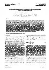
vessels. The operating mode of the whole system involves two steps in a cyclic mode: in the first vessel, the first transformation is endothermic and releases the reactive fluid, which is transferred to the other vessel where the fluid is consumed by another transformation, an exothermal one. In the second step, by a proper change of the thermodynamic operating conditions, the transformations are reversed and the fluid flows back to the first reactor. The temperature level of the endothermal and exothermal effects can be adapted to the available source and users by a proper selection of the reactive salt and gas (Neveu et al, 1993). As described by Figure 1, such system can fulfill the particular purpose of transportation of thermal energy. In that case, the two transformations occur on two remote sites, and they exchange the reactive fluid through a pipe network between the two sites. In the first step (see Fig.1), the endothermal reaction is carried out on the source site, using the available source heat at TS. Then, on the user site, the fluid is involved in an exothermal reaction and consequently releases heat to the user. In the second step, the system must be regenerated i.e. the reverse reactions is carried on and the reactive fluid is sent back to the source site. This second step will occur at a lower temperature: on the user site the endothermal reaction uses free ambient heat, while on the source site, low temperature heat produced by the exothermal reaction is rejected to the environment. Obviously, the reagents have to be correctly selected and the operating thermodynamic conditions properly fixed to suit to this cyclic working (Mazet et al., 2009). It is worth noting that one can take advantage of the endothermal process occurring on the user site: this temperature TU,cold can be low enough for a cold application
*This paper is an updated version of a paper published in the ECOS’10 proceedings. It is printed here with permission of the authors and organizers. ** Corresponding Author Vol. 15 (No. 3) / 177
on the user site. This application required a reactive pair whose working temperatures are shifted down compared to the previous ones. User Site
High temperature step Low temperature step
Transport
Source Site
i) Waste heat ii) Heat production
Heat source
TU,hot
TS
Exothermal process
Fluid
Endothemal process
Endothermal process
Fluid
Exothermal process
TU,cold
i) Cold ii) Free source
Heat release
Thus these thermochemical systems allow producing several functionalities on the user site: cold production, heat production or heat upgrading (i.e. TU,hot>TS). This multifunctionality is a really innovative characteristic of this concept. As the fluid is always transported at ambient temperature, the source-to-user distance less affects the energy transportation efficiency. It is another important advantage of such a process for energy transportation. It must be noted that this process does not transport thermal energy, but it transports a fluid that allows a thermal production on each site. Nevertheless, for the sake of simplicity, this system is called a thermal energy transportation system here after. For a thermal energy transportation system based on solid-gas reactions, the plant should involve two solid gas reactors (using two different reactive pairs), one on the source site and the other on the user site, coupled by the transportation of the reactive gas between them (Spinner et al., 2002; Bach et al., 1998; Kato, 2006; Mazet et al., 2009). For such transformation, the operating conditions are usually plotted on a Clapeyron diagram (Ln(P/P0) vs 1/T, Figure 2a). In such a diagram, solid/gas equilibrium conditions (p, T) are approximately displayed by a straight line. For the first step, the endothermal decomposition of pair 1 occurs on the source site using the high temperature source, while the exothermal synthesis reaction of pair 2 takes place and provides heat to the remote user. For the second step, these solid-gas reactions are reversed: using a free low temperature source on the user site, the decomposition of pair 2 is carried out, allowing the gas to flow back to the source site, and the synthesis of pair 2 on source site. For such solid-gas sorption system, the two steps correspond to high and low values of both operating temperature and pressure. Recall that to change from the low to high pressure step, the reactor is disconnected from the low pressure pipe and heated. Therefore, the reactor pressure increases according to the Clapeyron relation represented by the equilibrium line on Figure 2. Thus, this pressurization does not require any additional mechanical work. Once the high pressure is reached, the reactor is connected to the high pressure pipe.
Source Site solid1-gas
0
solid2-gas synthesis
Pcond
Pevap
solid1-gas decomposition
gas
gas solid2-gas decomposition
solid1-gas synthesis
Tu
-1/T
Tsource (2a)
T out
Figure 1. Principle of the thermal energy transportation over long distance by a single-effect thermochemical process, using a remote source at TS, to provide heat at TU,hot (ii) or cold at TU,cold (i) to the user.
178 / Vol. 15 (No. 3)
User Site solid2-gas Ln P/P
Ln P/P0
Source Site liquid-gas solid-gas cond
Pcond
solid-gas decomposition
User Site
liquid
evap. gas
Pevap
solid-gas synthesis
Tu,cold
-1/T
Tsource
(2b) Figure 2a and 2b: Operating conditions of a thermal energy transportation by a solid-gas sorption process, using a remote source at TSource to provide: a) heat at TU; b) cold at Tu,cold. The black lines are the equilibrium conditions of the solid-gas reaction. The pink lines refer to the transported fluid and the pressure at both ends of the pipes. (Figure is in color in the on-line version of the paper). For the peculiar purpose of cold production, it is well known that the evaporation of a fluid is the most relevant transformation. Thus the process can couple the phase change of a fluid on the user site and a solid/gas reaction involving the same gas on the source site. As the evaporator is the single component that must be on the user site, the system described in Figures 1 and 2a can be slightly simplified and improved: the evaporator is the single component located on the user site while the condenser is located on the source site. The solid-gas reactor remains on the source site (Figure 2b). As a result, during one step (the cold production step) the reactive gas is produced at the evaporator and then flows to the reactor on the source site while during the other step the gas produced by the reaction is condensed on source site and then it flows as a liquid to the user site. A thermal energy transportation system can also be based on liquid-gas sorption (ab-sorption). Such a system works in a similar way as solid/gas systems, and it could be used for the same purpose of transportation of thermal energy for cold production (Kang et al., 2000; Liu et al., 2002; Akisawa et al., 2005; Ma et al., 2010). The generator and condenser should be on the source site, the absorber and evaporator on the user site (Figure 3). But, liquid/gas systems have several drawbacks compared to solid/gas thermochemical systems. First they require the transportation of 3 fluids: the rich solution, the poor one, and the condensate. Second, they need mechanical energy to drive these fluids: it is mandatory for the poor solution, Int. Centre for Applied Thermodynamics
and the difference between the high and the low pressures is much lower than for solid gas systems and it could be too low for the fluid transportation. Ln P/P0
Source Site Condenser
condensate
Evaporator
Poor solution
R
Generator Rich solution
Absorber User Site
Tu cold
T
T source
Figure 3. Operating conditions of a thermal energy transportation based on a liquid-gas absorption, using a remote source at TSource, to provide cold at TU cold. The pink lines refer to the 3 transported fluids and their pressures. (Figure is in color in the on-line version of the paper). Accordingly, absorption systems are not considered in this paper, which is focused on the most promising thermochemical systems for transportation of thermal energy, and its comparison with classical ways of energy transportation. Thermal energy transportation systems based on solidgas thermochemical processes are investigated at CNRSPROMES for several years (Spinner et al., 2002; Spinner et al., 2005; Mazet et al., 2009; Le Pierrès et al., 2009). We have thoroughly studied several concepts of cycles (single effect or cascade) fulfilling the requirements of the transport of thermal energy, and analyzed the potentialities of these concepts according to the reactive pairs. Now, the performances of these systems have to be evaluated, according to operating temperatures, power, source-to-user distances, etc. In order to strengthen this analysis, classical processes of energy transportation (i.e. electricity network coupled with a heat pump, transport by coolant (sensible heat) or slurries (latent heat)) are included in this evaluation. The final objective of this work is to rank these various systems and to define the scope of relevance of each process according to the temperatures of the source and the users, and the distance for transportation. 3. Comparative assessment This assessment will compare the innovative thermochemical processes and the classical systems. All of them operate through one of four means: 1. An electrical network : the most classical exergy system transportation (i.e. electricity coupled with a mechanical heat pump on user site) involves a conversion step from waste heat to electricity. The low temperature of the waste heat used as heat source can disadvantage the energy efficiency of this system.
4. Reactive fluid network (gas or liquid) coupled with solid/gas thermochemical converters on the user and source sites, as described in Section 2. This last means takes advantage of a fundamental difference from the other systems: when transporting chemical reagents, the pressure drop has usually a weak effect on the chemical potential, so that the exergy output on the user site has nearly the same value as the exergy input at the source site, whatever the distance is. For this assessment, all of the systems are driven by the same heat source available on the source site at a given temperature, and all of them produce the same utility on the user site. In this paper, we focus on the recovery of industrial waste heat as heat source, and on cold production for air conditioning applications on the user side. 3.1. Principle A general method has to be developed to assess the performances of all these paths of energy transportation on the same basis, whatever the form of the transported energy is (chemical, mechanical, etc.). Thermodynamics offers such a tool, namely exergy analysis (Prigogine, 1968). All these processes can be divided in three sub-systems (Figure 4): two 'exergy converters', coupled to the exergy transportation network. User site
Source site
qU exU
Ts
n
Tu1 ex ,
ex1'
ex1
ex ex
' 2
ex 2
q S ex S
n
Tu2
Figure 4. Generic scheme for thermodynamics analysis of energy transportation. Each sub system is characterized by its exergy efficiency or exergy destruction:
▪ The converter on the source site converts the waste heat in a flow n of an extensity (electrons, gas, liquid, solid), characterized by a specific exergy ex. The exergy efficiency of this conversion process is defined as:
S n ex1 ex2 qS 1
T0 TS
(1)
▪ The transportation network, which transports this extensity through one or several pipes to and from the user site. It involves exergy losses, characterized by an exergy destruction:
exD n ex1 ex1' ex2' ex2
(2)
2. A coolant network that widely exists as district heating or cooling system, but the length of the network is usually limited beyond 10 km. It is based on the sensible heat of the transported liquid.
▪ The converter on the user site which produces the useful
3. A slurry network (ice slurry), that also exists as cooling systems. It involves the phase change of the transported fluid.
U qU 1
Int. J. of Thermodynamics
heat or cold. Its exergy efficiency is:
T0 ' ' n ex1 ex2 TU
(3)
Vol. 15 (No. 3) / 179
Then, the overall exergy efficiency and the overall energy efficiency can be easily deduced:
exU exS
(4a)
T qU qS .1 0 TS
T0 1 TU
(4b)
Eqs 1 to 4 clearly demonstrate the strength of exergy analysis, permitting to compare different types of processes with a unique generic formulation. Another advantage of using exergy efficiencies rather than energy efficiencies to describe the converters is that the former always lies between 0.3 and 0.5, depending on the complexity and the development of a technology, while the latter depends on both technologies and operating temperatures. 3.2. Assumptions for systems under study The systems under study are described in Figure 5. All these systems are only fired by a heat source at TS (waste industrial heat for example): we fixed TS=100°C. When mechanical energy is required (for pumps or electricity transport), it is produced by a converter using the same input thermal source at TS. All these systems provide the same cold utility on the user site. Thus, the user site operating conditions are fixed as: TU1=8°C, TU2=13°C. Moreover, we fixed a typical value for cold power: qU=20 MW.
Source site qs
Converter qo
Ts
User site whv
w’lv
w’hv electricity
Tu1=8°C
Chiller qu=20MW
q’o
Tu2=13°C
wp
Converter qo
qs
T1
Ts
Chiller q
e=0.8
q’ coolant
T2
qo
Tu1=8°C
coolant T’1
qu=20MW Tu2=13°C
T’2
- Heat exchanger effectiveness is e=0.8 (Incropera, 2007) and the energy efficiency is =1 (no thermal losses); - The reference temperature for the exergy analysis is T0=Tair= 35°C in summer. - The temperature of the soil surrounding the pipes is Tsoil=20°C. - The energy efficiency for the transport of electricity by extra-high voltage transmission lines is hv=0.97 and the efficiency of the conversion from extra-high to low voltage is hv/lv=0.9 (ERDF, 2010). In this case, the energy and exergy efficiencies are equal. 3.3. Methodology The methodology consists of evaluating the system, starting from the user site and going towards the source site. On the user site, the cold power and the operating temperatures are known, thus the output exergy is:
T exU qU . 1 0 TU TU
qU . U
TU 1 TU 2 Ln(TU 1 TU 2 )
(5)
Additional classical assumptions (heat exchange and pressure losses parameters, fluid velocities, etc.) are necessary to calculate step by step the state variables T, P (and x for two-phase flows) at each key point of the system (noted in Figure 5), and then to deduce the global exergy performance of the whole system. According to the process, the exergy destruction due to the transport and the exergy efficiency on the source site are evaluated as follows.
▪ Electricity network : The electric power required at the source site outlet is: whv exU hv .hv / lv .ch exS .el
(6)
wp
Converter qo
qs
thus the inlet thermal power is:
x1
Ts
Chiller
q
Ts
Reactor
qs
qo
Cond
qo
solution 1
liquid
2
gas
Tu1=8°C
e=0.8
q’
x2
qo
x’1
slurry
x’2=0
qu=20MW
2’
Evap
Tu1=8°C qu=20MW Tu2=13°C
Figure 5: Energy transportation systems under study. Transport of: a) electricity, b) coolant, c) slurry, d) reactive fluid. The following assumptions are required depending on the process: - According to industrial standards (Favrat, 2008) we assume that all the thermodynamic converters (motor, converting heat to electricity, chiller converting heat to cold) have the same exergy efficiency: C=el=ch=0.4. Due to the lack of industrial standards, the exergy efficiency of the thermochemical reactor is calculated. 180 / Vol. 15 (No. 3)
. el
hv
.hv / lv .ch .
(7)
Tu2=13°C
1’
q’
~ qS qU . U S
and the overall exergy and energy efficiencies are:
el .hv .hv / lv .ch
(8a)
. S U
(8b)
▪ Coolant network : The temperatures of the coolant at the ends of the transport lines are calculated thanks to the expressions of: - the effectiveness of the user heat exchanger e = (TU2TU1)/(TU2-T’1) = 0.8, - the thermal power supplied to the user qu, - the steady state heat balance of each line:
0 qi m.(hi hi' )
(9)
Int. Centre for Applied Thermodynamics
where the heat losses qi on each line are:
qi hSi .(Ti Ti ' ) / Ln((Ti T0 ) / (Ti ' T0 ))
(10)
and the enthalpy variations (assuming an incompressible liquid are:
hi hi' c(Ti Ti ' ) v( pi pi' )
(11)
For the transport pipes, typical values of roughness (r = 0.1 mm) and liquid velocity (u = 3 m/s) are used to estimate the pressure drop (using Colebrook correlation, see Incropera, 2007, Chapter 8). The pipe diameter is deduced from u and qU, which gives the coolant flowrate. The heat exchange h is fixed (h = 5 Wm-2 K-1). Thus, one can calculate the cold and mechanical powers supplied by the source site to the pipe network:
q m.c.(T1 T2 )
q m. csolution .(T2 T freezing ) cslurry .(T freezing T1 )
w m.v. p1 p1' p2' p2
(12)
w
T
T1 T2 Ln(T1 T2 )
(13)
and the overall exergy and energy efficiencies are:
qU . U exS
. S U
(14a) (14b)
▪ Slurry network : This system is similar to the previous one on the source and user sites. It only differs in the thermodynamic data of the transport fluid (a slurry). Among the very few slurries described in the literature, we have selected two of them: - An ice/ethanol slurry which has been studied for cold production applications by several authors (Bel, 1999; Ionescu, 2007; Kousksou, 2007; Marvillet, 2003). The alcohol mass ratio wa=10% leads to a freezing temperature at -4°C. Due to technical limits with pumps and valves, the ice mass ratio must be lower than wi=40% (Marvillet, 2003). Thus, for wa=10% and wi=0 to 40%, the temperature of the water-ice-ethanol slurry varies from -4 to -8°C (Kousksou, 2007). The variations of the density, viscosity and enthalpy of the two-phase solution according to the ice mass ratio and temperature are calculated thanks to published data (Bel, 1999; Kousksou, 2007). Then, an equivalent specific heat of the slurry is deduced from a linear regression of the enthalpy variation vs. T. Moreover, we assume that the slurry is fully melted at the outlet of the Int. J. of Thermodynamics
1 1 w m. p1 p1' p ' p2 solution 2 slurry
Two conversions are required on the source site: a heatto-cold conversion by means of a sorption chiller (to cool the coolant) and a heat-to-electricity conversion (to produce the power for the pumps). Both are assumed to have the same exergy efficiency: ch el 0.4 . Thus, the input exergy is:
T exS q. 1 0 T
user site i.e. x2' 0 . Thus, the fluid that flows back to the source is a one-phase water/ethanol solution. For sake of simplicity, we also fixed the ice ratio at the inlet of the user site : x2' 0.2 . - A TBAB hydrate slurry : this fluid is a mixture of TBAB (tetra-n-butylammonium bromide) and water. It is interesting because its phase change temperature is close to the temperature required for air conditioning: at an initial mass concentration of TBAB at 15%, the melting temperature is 8.9°C. Thus, the destruction of exergy on the site user should be weaker. The calculation methodology is similar to the ice slurry one, although very few physical and thermodynamic data are available for this innovative slurry (Darbouret, 2005). Finally, with this set of data, we are able to calculate the thermal energy provided by the source and the mechanical power required for the transportation for both the solution and slurry:
(15)
The exergy and energy efficiencies are defined as before (Eq. 14).
▪ Thermochemical process : For cold production applications, the solid/gas system described in Figure 1 can be designed in the simpler way described Section 2 and Figure 2b. The evaporator is located on the user site, while the solid/gas reactor and condenser are on the source site. Thus, the reactive fluid flows in liquid phase from the condenser on the source site, to the evaporator on the user site. Then, it flows back in gas phase from the evaporator to the solid-gas reactor, where the synthesis reaction occurs. Thermochemical processes present an intrinsic pressure difference between the condenser and evaporator. In a classical working, this pressure drop is released in a throttling valve and the corresponding exergy is lost. In this long distance transportation process, one can take advantage of that interesting peculiarity: this pressure difference can be used to drive the liquid flow from the source to the user site (Mazet, 2009) as described in Figure 6. Source Site liquid-gas solid-gas
Ln P/P0 P cond
D p1max P evap
D p2max
User Site
cond
p1
solid-gas decomposition
liquid
p’1 p2 evap.
gas solid-gas synthesis
p’2 Tsoil
-1/T
Tair
Tu,cold Tsource Figure 6. Operating pressures for the transportation of fluids in a thermochemical process.
Vol. 15 (No. 3) / 181
Exergy efficiency
Once condensed at Tair, the liquid is first subcooled at Tsoil and then flows from the source site to the user site driven by the available pressure difference: Dpmax=pcondpevap where pcond and pevap are the saturated pressures at respectively Tair=35°C (summer ambient air, used as heat sink for the condenser) and Tevap=6.8°C (the required evaporator temperature, assuming the effectiveness of the evaporator e=(TU2-TU1)/(TU2-Tevap)=0.8 as in the previous section). Nevertheless, in order to be sure to transport a singlephase phase fluid and to avoid any bubbles in the line, the pressure at the end of the line must be higher than p sat(Tsoil), so the pressure drop which is available for the transport is Dp1 = (p1-p1') = (pcond-psat (Tsoil)) (see Figure 6). The residual pressure drop Dp’1=(p1’'-p1'')=(psat(Tsol)–pevap) requires to feed the evaporator with a throttling valve. For the back flow line, the gas pressure is bounded by psat(Tevap) on the user site, and by the operating pressure of the synthesis reaction that occurs in the reactor on the source site (Figure 6) psyn= peq(Tair)+ Dpeq where Dpeq is the deviation from the equilibrium required for the reaction (corresponding to the usual temperature drop DTeq=10 °C). For this line: Dp2=(p2’ –p2)= (pevap -psyn). Thus, unlike the previous cases, the pressure drop between user and source sites is fixed in both pipes. Thus, the fluid velocities and pipe diameters are then deduced from the known Dp and mass flowrates. Moreover, heat losses are neglected as the fluid is assumed at the soil constant temperature (20°C) all along both pipes. Last, for this innovative process, the exergy efficiency is not given but it is calculated (from enthalpies, temperatures and pressure of the inlet and outlet fluids of all the components on the source site). For sake of simplicity in this assessment, we consider the reactive pair CaCl2/NH3, whose thermodynamic data are well known (Fenghor, 1995; Touzain, 1999).
0,35
Electricity+PAC
0,3 0,25 0,2 0,15 0,1 0,05 0 0
20
40
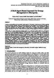
. S U
where
S U 1.9
60
Distance (Km) 80 100
Figure 7: Exergy efficiencies of the 4 systems transporting thermal energy from a source at TS=100°C, and producing cold (TU=8/13°C) on the user site. Complementary information is given by the analysis of the exergy destructions in each part of the energy transportation system. They are defined as follows: - source site :
exSD qS .S ex
(16)
- transportation:
D exTR ex ex'
(17)
- user site :
exUD ex' exU
(18)
An example of these exergy destructions is plotted in Figure 8, for L=50km. Figure 9 presents the numbers of exergy destruction Nk exkD exS (i.e. the ratio of the destruction of exergy to the inlet exergy exS) according to the process and the distance between source and user sites. Notice that we have:
exU exS 1 k
exkD exS
(19)
60
Exergy (MW)
4. Results 4.1. Exergy analysis Figure 7 compares the exergy efficiencies vs. the transportation distance for these four energy transportation processes. The energy efficiencies or COP are not presented: they are directly deduced from the exergy efficiencies as the temperatures TS, TU are fixed (see Eqn 4). Thus:
Sensible Coolant (sensible heat) Coulis de glace Ice slurry TBAB slurry Coulis de TBAB Solid/gas Solide Gazsorption CaCl2 8/4 NH3
exd source exd transport
50
L=50 km
exd user 40
inlet exergy : s ex_source=qs*teta_s
30 20 10
First, Figure 5 demonstrates that a thermochemical process transporting reactive fluids at ambient temperature is relevant for a wider range of distances. As the transportation of the reactive fluid is driven by the existing pressure difference between the condenser and the evaporator, this system can work without any additional pumping expenditure. Similarly, the flow back to the source site is driven by the existing pressure difference between the evaporator and solid-gas reactor. Thus, the exergy destruction due to the transport and the exergy efficiency does not depend on the distance. For the recovery of such waste heat, the thermochemical system is more efficient than electricity transportation driven by the same source, and coupled with a heat pump.
182 / Vol. 15 (No. 3)
0 sens.
ice
TBAB
S/G
Figure 8 : Exergy inlet on the source site, and exergy destruction for the different components of the systems. Distance source to user sites is 50 km. (Figure is in color in the on-line version of the paper). The low performances of the ice slurry can be explained by the temperature of the coolant which is significantly lower that the demand (TU). Figures 8 and 9 clearly show this fact: the user site exergy destruction is much higher for the ice slurry than for the other processes, due to the mismatch between slurry freezing temperature and chilled water temperature. The TBAB slurry overcomes this problem and is considerably more interesting. It can be Int. Centre for Applied Thermodynamics
sensible
ice slurry TBAB slurry S/G sorption
0,9 0,8
N source
0,7
N transport
0,6
N user
0,5 0,4
Exergy efficiency
0,3
0,2 0,1
50km
10km
50km
10km
50km
10km
50km
10km
0,0
distance (km)
Figure 9 : Number of exergy destruction (ratio of the exergy destruction to the inlet exergy exS) due to the conversion on the source site, transport and conversion on the user site, for the 4 systems investigated. Distance source to user sites: 10 and 50 km. (Figure is in color in the online version of the paper). As the exergy efficiency of the converters on the source site is fixed for all the classical systems (C=0.4, see Figure 5a,b,c), this part of the exergy destruction is the same for these three systems: NS = 0.6. For sorption systems, this exergy efficiency and Ns are calculated (S CaCl2/NH3 = 0.79). These figures show that the user site (involving only evaporators and exchangers) has a weak effect, as it leads to less than 10% of the exergy destruction for all the systems. The source and the transportation have a more important effect, and these figures exhibit a significant difference between systems based on a coolant or slurry and a reactive fluid. The sorption process presents a higher efficiency thanks to the weak exergy destruction on the source site. Notice that this value mainly depends on the reactive pair and on the corresponding operating conditions. To conclude, the exergy destruction are much lower for transportation systems based on sorption than others systems. As the output exergy is constant for all the processes, the required exergy input is also lower:
exS exU exkD
(20)
k
4.2. Flowing conditions The last comparison deals with the flowing conditions for the transportation of fluids between source and user sites. They are summarized as follows (for qU = 20 MW on the user site): - For the coolant and slurries: the velocity is fixed and the pipes diameter is deduced from qU. The pressure drop Dp/L is calculated from a well-known correlation. The results are: d=0.6 m, u=3 m/s,Dp/L=2.8 bar/km for the coolant, 0.56 bar/km for ice slurry and 0.45 bar/km for TBAB slurry. - For the reactive fluid : the total pressure drop is fixed, and the velocities and diameters depend on the distance of transport (Table 1). The gas velocities are rather high but these flows are driven by the pressure differences between the components of the process and not by a pump.
Int. J. of Thermodynamics
The smaller pipe diameters are obviously for the sorption process. Therefore, the thermochemical process presents a significant advantage regarding the civil engineering required for the network and the related investment costs. This benefit can be highlighted by the density of transported energy QU, i.e. the energy provided to the user divided by the sum of the cross sections of the two pipes in each system. For the coolant and slurries, QU=36.6 MW/m2, while QU ranges from 87 to 45 MW/m2 for the sorption process (see table1, last column). 4.3. Energy analysis The energies qs that fire the systems on the source site are deduced from the exergy efficiencies (Eqns. 4 & 14). On the other hand, the flowing conditions allow calculating the energy required to transport the fluids through the two pipes. All these energies are plotted in Figures 10a and 10b. They have to be compared to the useful heat power qU=20 MW. 300
Qs (MW)
N1,0
Table 1 : Flowing conditions of the reactive fluids coupled with a solid./gas sorption process. Source->user User->source Qu (liquid) (gas) MW/m2 d u d u 10 km 0.19 1 0.54 23.6 86.8 20 km 0.22 0.76 0.62 17.9 65.7 50 km 0.26 0.52 0.75 12.4 45.4 4.9 2.5 Dp (bar)
coolant ice slurry TBAB slurry Solid gas (CaCl2,8/4NH3)
250 200
150 100 50
0 0
20
40
60
80
100
Distance (km)
Mechanical power (MW)
more efficient than a thermochemical system for distances lower than about 10 km.
20 coolant ice slurry TBAB slurry Solid-gas (CaCl2,8-4NH3)
15
10
5
0 0
20
40
60
80
100
distance (km)
Figure 10 : Energies used by the four systems to produce 20 MW on the user site: a) thermal energy input; b) energy used to transport the fluid . Figure 10 highlights the limits of coolant and slurry systems and the advantages of sorption systems for heat transportation at distances over about 10 km.
Vol. 15 (No. 3) / 183
5. Conclusion A methodology has been developed to assess the various systems fulfilling the requirements of the transportation of heat over long distances. It is based on an exergy analysis of the three parts of such system: the source and user sites, and the lines transporting the fluids. Classical and an innovative system involving a solid/gas sorption are investigated. The general methodology is explained. Then it is applied to the particular example of the recovery industrial waste heat at low temperature on the source site, and to the cold production for air conditioning applications on the user site. Thus, all the systems under study are fired by the same low temperature heat source (at 100°C), and provide the same cold utility to the user. Several criteria are analyzed: the exergy efficiency of the whole system, the destruction of exergy in each part of these systems, the energy input and the flowing conditions of the fluids. As expected, the coolant system is less efficient than the other ones for all the above criteria for distances over 5 km. The low performances of the ice slurry can be explained by the temperature of the slurry which is significantly lower that the demand (TU). The TBAB slurry overcomes this problem and is more interesting. It can be more efficient than a thermochemical system for distances lower than about 10 km. The system based on the transport of electricity coupled with a heat pump is less efficient than a sorption system, mainly due to the low energy efficiency of the conversion of low temperature heat to electricity on the source site. For distances over 10 km, all the above mentioned criteria are consistent to demonstrate the relevance of thermochemical sorption systems for the recovery of low temperature heat to produce cold for remote users. Acknowledgements: This work is supported by the PIE-CNRS (Interdisciplinary energy program) funded by the CNRS (Centre National de la Recherche Scientifique) in the framework of the project ‘VALOTHERM’. Nomenclature c specific heat, J/(kg K) equivalent specific heat of the slurry, J/(kg K) c~ d pipe diameter, m e heat exchangers effectiveness ex exergy, W h heat transfer coefficient, W/(m2.K) hi specific enthalpy, J/kg m mass flow rate, kg/s n flow of an extensity (electrons, gas, liquid, solid), N=exD/exS number of destruction of exergy p pressure, Pa q thermal power, W QU density of energy transported (refered to the total cross section of the pipes), MW/m2 S pipe external surface, m2 T temperature, °C T T ~ equivalent temperature T 1 2 T Ln(T1 T2 ) u fluid velocity, m/s 184 / Vol. 15 (No. 3)
w wa, wi w x
mechanical power, W alcohol, ice mass ratio in the slurry mechanical ice mass ratio in the slurry
Greek symbols energy efficiency η exergy efficiency (without subcript: overall value) v specific volume, m3/kg density, kg/m3 ~ ~ Carnot factor , u Subscripts and superscripts 1 source to user pipe 2 user to source pipe 0 refer to environment C converter ch chiller cond condenseur D destruction air ambient air evap evaporator el electrical eq equilibrium hv, lv extra-high voltage, low voltage lines hv/lv from extra-high to low voltage i,s source site L source to user distance soil soil syn synthesis reaction TR transport ’ ,U user site S source site References: Akisawa A, et al., 2005. Performance of thermal energy transportation based on absorption system–Solution Transportation Absorption chiller. International Sorption Heat Pump Conference, June 22–24, Denver, Bach, P., Haije, W., 1998. Transformation and Transport of Heat Along the Thermochemical Route. 1st Workshop IEA Annex 10, Adana, Turkey. Bel, O., Lallemand, A., 1999. Etude d’un fluide frigoporteur diphasique, 1 : Caractéristiques thermophysiques intrinsèques d’un coulis de glace. Int. Journal of Refrigeration , 22, 164-174. Berthiaud, J., Mazet, N., 2006. Long-distance transport of thermal energy using sorption cycles. In: Proceedings of the ATI Conference,Milano, Italy,14–17 May; 2006. Darbouret, M., Cournil, M., Herri, J.-M., 2005. Rheological study of TBAB hydrate slurries as secondary two-phase refrigerants. Int. J. of Refrigeration, 28( 5), 663-671. ERDF, 2010. www.erdfdistribution.fr Favrat, D., 2008. The challenge of introducing an exergy indicator in a local law on energy. Energy,33, 130–136. Fenghor, A., et al., 1995. The viscosity of Ammonia, J. of Physical and Chemical Reference Data, 24, 1650-1667.
Int. Centre for Applied Thermodynamics
Hasegawa, H., et al., 1998. Analysis on waste-heat transportation systems with different heat-energy carriers. Applied Energy, 61,1-12. Hoehlein, B., et al., 1981. J. High temperature methanation in the long-distance nuclear energy transport system. App. Catal.1(3-4),125-139. IEA-ECES, Annex 18, 2010. Transportation of energy by utilization of Thermal Energy Storage Technology. www.iea- eces.org. Incropera, F.P., et al., 2007. Fundamentals of heat and mass transfer. 6th ed.,Wiley, Chap.11. Ionescu, C., Lallemand, A., 2007. Local and global heat transfer coefficients of a stabilised ice slurry in laminar and transitional flows. Int. J. of Refrigeration, 30 (6), 970-977. Kugeler, K., et al., 1975. Transport of nuclear heat by means of chemical energy (nuclear long-distance energy). Nuclear Engineering and Design, 34,65-72. Kang, YT., et al., 2000. Absorption heat pump systems for solution transportation at ambient temperature – STA cycle. Energy, (25),355-370. Kato, Y., 2006. Possibility of chemical heat storage in thermal energy transportation market. IEA, ECES IA Annex 18. 1st Workshop, Tokyo, Japan. Kousksou, T., et al., 2007. Equilibrium liquidus temperatures of binary mixtures from differential scanning calorimetry. Chemical Engineering Science, 62, 6516-6523. Le Pierrès, N., et al., 2007. Experimental results of a solar powered cooling system at low temperature. International Journal of Refrigeration, 30(6), 10501058. Le Pierrès, N., Luo L., Berthiaud J., Mazet, N., 2009. Heat transportation from the Bugey power plant. Int. Journal of Energy Research, (33)2,135-143. Liu, Q., et al., 2002. A review of study on thermal energy transport system. JSME Int.J, B, 45(3), 473-480. Ma, Q., , Luo, L., et al., 2010. Performance analysis and validation on transportation of heat energy over long distance by ammonia-water absorption cycle, Int. Journal of Energy Research, 34( 10), 839–847. Marvillet C., 2003. Fluides frigoporteurs : Propriétés, Techniques de l’Ingénieur – BE Génie énergétique, BE 9 572, 1-14. Martin, V., et al., 2006. System design for efficient transportation of industrial waste heat . IEA-ECES Annex 18, 1st Workshop Tokyo, Japan
Int. J. of Thermodynamics
Mazet, N., et al., 2009. Feasibility of long-distance transport of thermal energy using solid sorption processes. International Journal of Energy Research, (34)8,673-687. Mazet, N., et al., 2010. Comparative thermodynamic assessment of processes for the transportation of thermal energy over long distances. ECOS 2010, Lausanne. Nasako, K., et al., 1998. Intermittent heat transport using hydrogen absorbing alloys. Int. J. Hydrogen Energy, 23( 9),815-824. Neveu, P., Castaing-Lasvignottes, J., 1993. Solid-gas chemical heat pumps: Field of application and performance of the internal heat of reaction recovery process. Heat Recovery Systems and CHP, 13(3), 233251. New Sunshine Program: sub-topic: Eco-Energy City- Broad Area Energy Utilization Network System Technology,www.nedo.go.jp/itd/fellow/english/projecte/5e.html Pons, M., et al., 1999. Thermodynamic based comparison of sorption systems for cooling and heat pumping. International Journal of Refrigeration, 22(1), 5-17. Prigogine, I., 1968. Introduction à la thermodynamique des processus irréversibles. Dunod. ISBN 2-87647-169-8 Spinner, B., et al., 2002. New sorption cycles for heat and/or cold production adapted for long distance heat transmission. American Society of Mechanical Engineers, Advanced Energy Systems Division, AES 42, 441-446. Spinner, B., et al., 2005, New cascades for thermo-chemical refrigeration, Int. journal of thermal sciences, 44(12), 1110-1114. Stitou, D., et al., 2002. New sorption cycles for heat and/or cold production adapted for long distance heat transmission. ASME Adv Energy Syst Division AES, 42,441–6. Stitou, D., et al., 2011. Experimental investigation of a solid/gas thermochemical storage process for solar airconditioning. Energy, Online 3 September 2011 Touzain, P., 1999, Thermodynamic values of ammonia salts reactions for chemical sorption heat pumps. International Sorption Heat Pump Conference, Munich, Germany. Zeng, W., et al.,1992. Application of chemical heat pipe using SO2/SO3 reversible thermochemical reaction to the transportation of high temperature thermal energy. IAEA-TECDOC-761.
Vol. 15 (No. 3) / 185