Edge Effects on the Electronic Structures of Chemically Modified Armchair Graphene Nanoribbons Hao Ren,1 Qunxiang Li,1, ∗ Haibin Su,2 Q. W. Shi,1 Jie Chen,3, 4 and Jinlong Yang1, †
arXiv:0711.1700v1 [cond-mat.mtrl-sci] 12 Nov 2007
1
Hefei National Laboratory for Physical Sciences at Microscale, University of Science and Technology of China, Hefei, Anhui 230026, P.R. China 2 Division of Materials Science, Nanyang Technological University, 50 Nanyang Avenue, 639798, Singapore 3 Electrical and Computer Engineering, University of Alberta, AB T6G 2V4, Canada 4 National Institute of Nanotechnology, Canada (Dated: February 2, 2008) In this paper, we apply the first-principle theory to explore how the electronic structures of armchair graphene nanoribbons (AGNRs) are affected by chemical modifications. The edge addends include H, F, N, NH2 , and NO2 . Our theoretical results show that the energy gaps are highly tunable by controlling the widths of AGNRs and addends. The most interesting finding is that N-passivated AGNRs with various widths are metallic due to the unique electronic features of N-N bonds. This property change of AGNRs (from semiconducting to metallic) is important in developing graphenebased devices. PACS numbers: 73.22.-f, 73.20.Hb, 72.80.Rj, 73.63.Bd
I.
INTRODUCTION
Graphene, a single atomic layer of graphite with a honeycomb crystal structure, has attracted a great number of research activities.1 Its structural properties, electrical conductance and quantum Hall effects have been investigated for making novel nanoelectronic devices.2,3,4 Due to the linear energy dispersion relation near the Dirac points, graphene is an interesting conductor in which electrons move like massless Dirac-fermions.3 It is now possible to make graphene nanoribbons (GNRs) with various experimental methods such as tailoring via a scanning tunneling microscopy tip,5 exfoliating from high oriented pyrolytic graphite,3,4,6 , or graphitizating SiC wafers.7 The energy gaps of GNRs with several tens of nanometers can be measured because the growth of the energy gap is inversely proportional to the GNRs’ width.8 There are two typical types of GNRs according to their edge configurations, either armchair or zigzag. Zigzag edge GNRs are metallic without considering the freedom of spin because the two edge states are degenerated at the Fermi level. Hydrogen-saturated armchair GNRs (AGNRs), on the other hand, are semiconductors.9,10 The electronic transport and magnetic properties of zigzag GNRs have also been studied by several research groups.9,11,12,13 Because of the high ratio between edge and inner atoms, the electronic structure of narrow GNRs are sensitive to various edge addends. Individual carbon atoms on graphene edges are only bounded to two neighboring carbon atoms and a dangling carbon bond offers a remarkable opportunity for altering GNR’s electronic properties. This edge modification can be implemented by attaching various atoms or functional groups to these dangling carbon atoms. To the best of our knowledge, edge modified AGNRs, except for the hydrogenpassivated GNRs, have not been systematically examined using Density Functional Theory (DFT). In this
paper, the electronic structures of AGNRs, with various addends including H, F, N, NO2 and NH2 , are thoroughly investigated based on first-principle calculations. Our results show that AGNRs can be either semiconducting or metallic by changing edge chemical addends. This remarkable characteristic is very useful in making graphene-based molecule computing or sensing devices. The detailed analysis of the electronic structures can also be used to understand the underlying microscopic mechanisms of these edge effects.
II.
MODEL AND METHOD
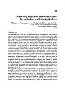
The electronic structure calculations are carried out by employing the Vienna ab initio simulation package with local density approximation.14,15 The electron-ion interactions are described based on the projected augmented wave (PAW) and the frozen core approximation.16 The energy cutoff is set to be 400 eV. Following the previous definition of AGNRs,9 we choose AGNRs with width W=18, 19, and 20 (corresponding to 3p, 3p+1, and 3p+2, respectively. Here, p is an integer) as examples to study three kinds of AGNRs. The schematic of a sample AGNR with width of W=18 is shown in Figure 1. Various addends, such as H, F, and N atoms, are connected to individual edge carbon atoms. In the NH2 and NO2 passivated cases, each edge carbon atom bonds to one NH2 or NO2 group alternatively (its neighboring carbon atom is saturated by an H atom). In our calculations, all atomic positions are allowed to relax. The convergence tolerance in energy and force is 2×10⁻⁵ eV and 0.02 eV/˚ A, respectively. The vacuum layers between two neighboring AGNR sheets and AGNR edges are set to be 12 ˚ A and 15 ˚ A wide, respectively. In a typical calculation, a one-dimensional periodic boundary condition along the edge direction is imposed. We choose the k-point sampling consisting of 15 uniform k-points together with the
2
FIG. 1: (Color online) Schematic of a sample AGNR with width W=18. The black dots correspond to carbon atoms while the blue ones represent the addends (labeled with X, where X can be H, F, N, 2H, 2F, NO2 , and NH2 molecules). The distance between two dash-dotted lines is the lattice constant of one-dimensional unit-cell in the DFT calculations. TABLE I: The calculated energy gaps (in eV) of X-AGNRs with width w=18, 19, and 20. Here, “M” stands for the metallic case without Egap . W 18 19 20
X= Egap (eV) Egap (eV) Egap (eV) ∆Ef (eV )a
H 0.41 0.61 0.10 -2.29
F 0.61 0.35 0.14 -3.78
2H 0.70 0.10 0.42 -1.35
2F 0.45 0.15 0.63 -3.06
NO2 0.38 0.57 0.09 -4.05
NH2 0.47 0.38 0.13 -2.77
N M M M -1.51
a Because there is not much difference in bandgaps when narrow graphenes are selected, only the formation energy of AGNRs with width w=18 is considered.PThe formation energy is defined 1 (Etot − Ebare − nX µX ), where Etot , Ebare , n, as, ∆Ef = n nX , and µX is the total energy of system, the energy of unpassivated 18-AGNR, the number of chemical groups, the number of atoms of addends X and the chemical potential of X, respectively. We choose the chemical potential of H, F, N, and O as the binding cohensive energy per atom in H2 , F2 , N2 , and O2 molecules. This definition would be a appropriate mesurement of the stability in passivated AGNRs. The formation energy of NO2 and NH2 passivated P 18-AGNRs per group is defined as ∆Ef = 21 (Etot −Ebare − nX µX −2×∆Ef (H)), where ∆Ef (H)) is the formation energy of H-passivated 18-AGNR.
Γ point.
III.
RESULTS AND DISCUSSIONS
We first choose the well-studied hydrogen passivated AGNRs9,17 as a basis to validate our numerical results. The calculated band structures of three kinds of hydrogen passivated AGNRs are plotted in Figure 2 (a). The corresponding bandgaps together with the optimized CC distances at the edge are listed in Table I. Our results show that all three kinds of AGNRs are semiconductors with direct band gaps at the Γ point. The figure clearly shows that the AGNR with width W = 3p + 1 has the largest energy gap, while the AGNR with width W=3p+2 has the smallest one. Our calculated bandgaps are 0.41, 0.61, and 0.10 eV for the H passivated AGNRs with width W=18, 19 and 20, respectively. These results agree well with the previously reported results9,17 . Next, we examine the electronic structures of AGNRs with F atoms passivated at both edges. The cal-
FIG. 2: (Color online) (a) and (b) show the band structures of H and F-passivated AGNRs with width W= 18, 19, and 20, respectively. (c) The projected density of states(PDOS) of H(upper panel) and F(lower panel) passivated AGNRs with width W=18.
culated band structures are plotted in Fig. 2 (b) and the bandgaps are listed in Table I. Similar to the Hpassivation cases, all F-passivated AGNRs are semiconductors. However, the effects of GNR width on bandgaps is clearly different. For instance, the F-passivation makes the band gap of the AGNR with width W=18 (3p) to be the largest (0.61 eV), while the gap of the AGRN with width W=20 (3p+2) is the smallest (0.14 eV). It is important to note that the bandgaps of the AGNRs (width W=20) with the smallest gaps remain as the smallest even after passivation. However, AGNRs with the largest bandgaps behave differently and depend on elements used for passivation. We also would like to know what happens if individual edge carbon atoms connect to two H or F atoms instead of one H or F atom. Intuitively, the sp2 hybridization of edge carbon atoms is converted into sp3 hybridization. The effective AGNR width is therefore reduced by 2. In other words, the effective width becomes 17 for both double H- and Fpassivated AGNRs when their initial width is W=19. Because the effective width of 17 fits 3p+2, the corresponding double H- and F-passivated AGNRs have the smallest energy gap (about 0.1 eV). The largest gaps are 0.70 eV for double H-passivated AGNRs with W=17 or effective W=16 (3p+1). Similarly, 0.63 eV for of double F-passivated AGNRs with W=20 or effective W’=18 (a 3p case). These results are consistent with the width de-
3 pendent energy gap features in single F- or H-passivated AGNRs. It is instructive to compare the DFT results with the tight-binding approximation (TBA) data. Wang et al. have reported that energy gaps can be tuned by changing edge hopping parameters.17 Son et al. have also showed that the energy gaps of H-passivated AGNRs can be reproduced via TBA simulations. In their simulations, edge hopping parameters can be increased by decreasing the bond length of C atoms at edges.9 Although the geometric deformations of carbon networks are almost the same between H-passivated GNRs and F-passivated ones, the bandgaps surprisingly show distinct dependence on the width of AGNRs. According to the TBA parameters adopted in these analytical calculations of the edge modified GRNs,18 the πpp hopping integrals, representing the coupling between pz orbital of two neighboring carbon atoms, increases as the C-C distance decreases. However, this statement is invalid when the bond length substantially decreases so that the hybridization between two carbon atoms becomes perturbed. From the PDOS of the H-passivated AGNRs, we can see that the peaks of pz orbital of edge C atoms almost coincide with that of the inner C atoms below the Fermi level [see Fig2(c)]. The πpp bonding remains unchanged during the H-passivation of edge C atoms. The modification of energy gaps caused by H atoms could be explained based on the geometry deformation. Interestingly, the pz orbital of both edge C atoms and F addends have peaks at −8.5 eV below the Fermi energy. The peak position of the edge C atoms, however, decreases significantly compared to the inner C atoms from −6.0 to −2.3 eV below the Fermi energy, which is still within the energy range of π bonding in Fpassivated AGNRs. That is to say, the pz orbital of edge C atoms in the F-passivated cases form chemical bonds with the neighboring C atoms and the F atoms. Consequently, the hopping parameters decrease. If we choose the hopping parameter to be 84% of -2.7 eV ( the typical hopping integral of sp2 carbon system), the energy gaps of AGNRs with width W=18, 19, and 20 are 0.65, 0.35, and 0.13 eV, respectively, which agree excellently with results obtained by DFT. This observation demonstrates that the electronic structures of AGNRs can be controlled by edge chemical modifications. NO2 and NH2 radicals are widely used as anchoring or side groups for making single molecular junctions in molecular electronics.19,20,21 In the next calculations, NO2 and NH2 are attached to AGNRs and we investigate how these addends impact GNR electronic structures. Figs. 3 (a) and (b) show their band structures. Figs. 3 (c) and (d) show their optimal geometric structures. The NH2 group lies in the AGNR plane for NH2 passivated GNRs, while, for NO2 passivated GNRs, the dihedral angle is 59◦ between AGNR and NO2 plane. According to the projected DOS in Figure 4, their electronic structures also exhibit different features. For the NH2 -passivated AGNRs, the nitrogen atom forms one sp2 orbital, which bonds to two hydrogen and one edge carbon atom. The
FIG. 3: (Color online) Band structures of NO2 -, and NH2 passivated AGNRs with width W = 18, 19, and 20 are show in (a) and (b), respectively. The edge relaxed geometric structures of NO2 and NH2 are shown in (e) and (f). The relaxed bond lengths from a1 to a6 are 1.36, 1.40, 1.39, 1.37, 1.42, and 1.37 ˚ A, respectively, and the bond angles from γ1 to γ4 are 122.8◦ , 120.6◦ , 117.5◦ , and 126.6◦ , respectively.
remaining pz orbital of the nitrogen atom bonds nicely to the pz orbital of the edge carbon. For the NO2 case, the π orbital in the NO2 plane does not bond well to the sp2 framework of AGNRs because the NO2 plane twists out of the AGNR sheet. Comparing to the bandgaps of H- and F-passivated AGNRs, it is interesting to note that the bandgap of NO2 is close to that of H, while the bandgap of NH2 is similar to that of F. The fundamental cause is attributed to the influences of the carbon pz orbital. Neither H nor NO2 forms a bond with the carbon pz orbital, but both F and NH2 facilitate bonding directly to carbon pz orbital. Hence, it is expected that substantial charge transfer occurs together with the nonnegligible change in the hopping integral near the edges of both F- and NH2 -passivated AGNRs. Very recently, N-rich Oligoacences were considered to be candidates for n-channel organic semiconductors.22 Ndoped carbon nanotubes and nanofibers have also been synthesized and investigated intensively over the past years.23,24,25,26 These investigations motivate us to examine the N-passivated AGNRs. According to the calculated formation energy in Table 1, it is possible to attach one N atom to each C atom along the edges as an addend. Interestingly, two neighboring N addends can form an N-N dimer and form an optimal structure. The N-N bond length is 1.30 ˚ A, which is 0.20 ˚ A longer than that of N-N bond length in N2 molecule. More importantly, a semiconductor-to-metal transition is observed for all N-passivated AGNRs and this transition is independent of AGNR widths. To explore the cause at the microscopic scale, the band structures of N-passivated AGNRs with various graphene widths and partial projected DOS
4
FIG. 4: (Color online) (a) Partial density of states (PDOS) of the edge C, and N in NH2 -passivated AGNRs. (b) PDOS of the C, N, and O atoms in NO2 -AGNRs. Here, W=18.
on N atoms of AGNR with width W=18 are presented in Figs. 5(a) and 5(b), respectively. Clearly, the DOS near the Fermi level is impacted by N addends. The edge N atom has 5 valence electrons. Two of them stay as a lone-pair, which locates in the AGNR’ plane with the direction pointing outwards. The occupied band labeled with “A” in Fig. 5(a) has the same features as those of lone-pair electrons. The other three electrons exhibit sp2 -like hybridization. Two of the sp2 hybridized orbital pair with the neighboring C and N atoms to form two σ bonds, while the last electron acts as a π electron. We would like to emphasize that the metallic state of N-passivated AGNRs is predominantly contributed by the edge states of N addends. There are two reasons attributed to AGNR’s semiconducting to metallic transition. i) the N-N bond is mainly composed of 2s and 2py orbitals. The energy of the band with N 2pz is above the Fermi surface, which means that N 2pz electrons fill the carbon π∗ bands and push the Fermi surface inside the carbon’s π∗ bands. ii) the lone-pair electrons of N atoms are mainly in N 2px bands and the top part of 2px
FIG. 5: (Color online) (a) Band structures and DOS of Npassivated AGNRs with width W = 18, 19, and 20, respectively. Here, the total DOS and projected DOS on N atoms are labeled with solid and dashed lines. (b) Partial projected DOS on N atoms of N-passivated AGNRs with width W=18. The relaxed geometry is shown in the inset in Fig.(b)
bands pass the Fermi surface. This feature contributes to the semiconducting to the metallic transition. Clearly, edge N-N addends extend the sp2 network of AGNRs and thus the effective width (or the number of sp2 dimer lines) of N-passivated AGNRs increases by 2 (coming from two edge sides). Apart from “A” band, the band structures of N-passivated AGNRs with width W are similar to those of H or F-passivated AGNRs with width W + 2 except that the Fermi level shifts upwards and cross the lowest unoccupied bands, which leads to the semiconductor-tometal transition. IV.
CONCLUSION
In summary, we perform the first-principle calculations on the electronic structures of AGNRs with various edge chemical modifications. We find that the energy gap can be tuned to be either metallic or semiconducting by attaching different chemical functional addends. After AGNRs are passivated by H, F, NH2 , and NO2 , the GNRs with the smallest bandgaps (i.e. W=20) remain to have the smallest bandgaps. However, AGNRs that have the
5 largest bandgaps behave differently and the gaps depend on the type of elements used for passivation. H and F have similar bandgaps to NO2 and NH2 , respectively, which can be explained based on the bonding of the carbon pz orbital. The fascinating observation is that AGNRs passivated by attaching N atoms can change from semiconducting to metallic material regardless of AGNR width. This result is analyzed in detail based on its electronic structure. The unique electronic structure of the N-N bond, which is responsible for semiconductor-tometal transition, is explained based on its 2s and 2py orbital, and the lone-pair of 2px . This tunable character of AGNRs is useful in developing graphene-based molecule electronic devices in the near future.
20773112, 10574119, 50121202, and 20533030, by National Key Basic Research Program under Grant No. 2006CB922004, by the USTC-HP HPC project, and by the SCCAS and Shanghai Supercomputer Center.Work at NTU is supported in part by a COE-SUG grant (No. M58070001) and A*STAR SERC grant (No. 0521170032). Jie Chen would like to acknowledge the funding support from the Discovery program of Natural Sciences and Engineering Research Council of Canada under Grant No. 245680.
ACKNOWLEDGMENTS
This work was partially supported by the National Natural Science Foundation of China under Grant Nos.
∗ † 1
2
3
4
5 6
7
8
9
10
11
12
13
Corresponding author. E-mail:
[email protected] Corresponding author. E-mail:
[email protected] A. K. Gein and K. S. Novoselov, Nature Mater., 6, 183 (2007). K. S. Novoselov, A. K. Geim, S. V. Morozov, D. Jiang, Y. Zhang, S. V. Dubonos, I. V. Grigorieva, and A. A. Firsov, Science 306 666(2004). K. S. Novoselov, A. K. Geim, S. V. Morozov, D. Jiang, M. I. Katsnelson, I. V. Grigorieva, S. V. Dubonos, and A. A. Firsov, Nature 438, 197 (2005). Y. B. Zhang, Y. W. Tan, H. L. Stormer, and P. Kim, Nature 438, 201 (2005). H. Hiura, Appl. Surf. Sci. 222, 374 (2004). J. S. Bunch, A. M. van der Zande, S. S. Verbridge, I. W. Frank, D. M. Tanenbaum, J. M. Parpia, H. G. Craighead, and P. L. McEuen, Science 315, 490 (2007). C. Berger, Z. M. Song, X. B. Li, XS Wu, N. Brown, C. Naud, D. Mayou, TB Li, J. Hass, A. N. Marchenkov, E. H. Conrad, P. N. First, and W. A. de Heer, Science 312, 1191 (2006). ¨ M. Y. Han, B. Oyilmaz, Y. B. Zhang, and P. Kim, Phys. Rev. Lett. 98, 206805 (2007). Y.-W. Son, M. L. Cohen, S. G. Louie, Phys. Rev. Lett. 97, 216803(2006); Y.-W. Son, M. L. Cohen, S. G. Louie, Nature 444, 347(2006). H. X. Zheng, Z. F. Wang, T. Luo, Q. W. Shi, and J. Chen, Phys. Rev. B 75, 165414 (2007). O. Hod, V. Barone, J. E. Peralta, and G. E. Scueria, Nano Lett. 7, 2295(2007). D. Gunlycke, J. Li, J. W. Mintmire, and C. T. White, Appl. Phys. Lett. 91, 112108(2007). D. Jiang, B. G. Sumpter, and S. Dai, J. Chem. Phys. 126,
14
15
16
17
18
19
20
21
22
23
24
25 26
134701 (2007). G. Kresse and J. Furthm¨ uler, Phys. Rev. B 54, 11169 (1996); Comput. Mat. Sci. 6, 15 (1996); G. Kresse and J. Hafner, Phys. Rev. B 47, R558 (1993); Phys. Rev. B 48, 13115 (1993). J. P. Perdew and Y. Wang, Phys. Rev. B 45, 13244 (1992); Rev. B 49, 14251 (1994). P. E. Bl¨ ohl, Phys. Rev. B 50, 17953 (1994); G. Kresse and J. Joubert, Phys. Rev. B 59, 1758 (1999). Z. F. Wang. Q. X. Li, H. X. Zheng, H. Ren, H. B. Su, Q. W. Shi, and J. Chen, Phys. Rev. B 75, 113406 (2007). D. Porezag, Th. Frauenheim, Th. K¨ oler, G. Seifert, and R. Kaschner, Phys. Rev. B 51, 12947 (1995). L. Venkataraman, J. E. Klare, C. Nokolls, M. S. Hybertsen, and M. L. Steigerwald, Nature 442, 904 (2006). L. Venkataraman, Y. S. Park, A. C. Whalley, C. Nuckolls, M. S. Hybertsen, and M. L. Steigerwald, Nano Lett. 7, 502 (2007). A. Star, T.-R. Han, J.-C. P. Gabriel, K. Bradley, and G. Gr¨ uer, Nano Lett. 3, 1421 (2003). M. Winkler and K. N. Houk, J. Am. Chem. Soc. 129, 1805(2006). M. Terrone, A. J. M. Endo, A. M. Rao, Y. A. Kim, T. Hayashi, H. Terrones, J.-C. Charlier, G. Dresselhaus, and M. S. Dresselhaus, Mater. Today 7, No. 10, 30 (2004). Z. Weng-Seih, K. Cherrey, N. G. Chopra, X. Blase, Y. Miyamoto, A. Rubio, M. L. Cohen, S. G. Louie, A. Zettl, and R. Gronsky, Phys. Rev. B 51, 11229 (1995). K. Harigaya, Jpn. J. Appl. Phys. 45, 7237 (2006). T. Yoshioka, H. Suzuura, and T. ando, J. Phys. Soc. Jpn. 72, 2656 (2003).