The 6-different specimen includes casting of A356(Base), along with ...... Parting off the specimen from the workpiece which is going to be observed for ... accomplished either wet or dry using 80 to 180 grit electrically powered disks or belts,.
B. TECH FINAL YEAR PROJECT REPORT ON
“EFFECT OF ADDITION OF CHROMIUM AND RARE-EARTH METALS IN A356” BY
KANISHK CHAUDHARY (U13ME137) HARSHIT YADAV (U13ME159) ANMOL GUPTA (U13ME166) NAVEEN S PREM (U13ME171) CHINMAY MITTAL (U13ME201)
Under the guidance of
Dr. JYOTI V MENGHANI Assistant Professor Mechanical Engineering Dept., SVNIT
Sardar Vallabhbhai National Institute of Technology, Surat – 395007 2016-17
1
CERTIFICATE This is to certify that the report of the project entitled
“EFFECT OF ADDITION OF CHROMIUM AND RAREEARTH METALS IN A356” Submitted by
KANISHK CHAUDHARY (U13ME137) HARSHIT YADAV (U13ME159) ANMOL GUPTA (U13ME166) NAVEEN S PREM (U13ME171) CHINMAY MITTAL (U13ME201) In fulfilment of the requirement for the degree of “Bachelor of Technology” in Mechanical Engineering during the year 2016-17, of the Sardar Vallabhbhai National Institute of Technology, Surat is the record of their own work carried out by them under the guidance of Dr. Jyoti V Menghani Assistant Prof. Mechanical Engineering Dept. (SVNIT). Date:
Guided by
Head of Department
Dr. Jyoti V Menghani
Dr. K. P. Desai
Department of Mechanical
Department of Mechanical
Engineering
Engineering 2
APPROVAL CERTIFICATE KANISHK CHAUDHARY (U13ME137) HARSHIT YADAV (U13ME159) ANMOL GUPTA (U13ME166) NAVEEN S PREM (U13ME171) CHINMAY MITTAL (U13ME201) registered students of Bachelor of technology course in Mechanical Engineering Department of Sardar Vallabhbhai National Institute of Technology, Surat have successfully presented and submitted their project report on the topic “EFFECT OF ADDITION OF CHROMIUM AND RARE-EARTH METALS IN A356” in front of following members of the committee.
Examiners
Sign
Date
1. Examiner-1
---------------------------
---------------------------
2. Examiner-2
---------------------------
---------------------------
3. Examiner-3
---------------------------
---------------------------
Date: 11/05/2016 Place: SVNIT, Surat
3
DECLARATION I confirm that this assignment is my own work and that I have:
•
Read and understood the policy on plagiarism of Sardar Vallabhbhai National Institute of Technology, Surat – 395 007, Gujarat state, India.
•
Clearly referenced, in both the text and the bibliography or references, all sources used in the work.
•
Fully referenced (including page numbers) and used inverted commas for all text quoted from books, journals, web etc.
•
Provided the sources for all tables, figures, data, etc., that are not my own work.
•
Not made use of the work of any other student(s) past or present without acknowledgement.
Not sought or used the services of any professional agencies to produce this work. In addition, I understand that any false claim in respect of this work will result in disciplinary action in accordance with Institute regulations.
DECLARATION:
I am aware of and understand the policy on plagiarism of Sardar Vallabhbhai National Institute of Technology, Surat – 395 007 and I certify that this Project is my own work, except where indicated by referencing, and that I have followed the good academic practices noted above. Date: ________________________
Signature: _______________________
Enrolment No. _________________
Name: __________________________
i
ACKNOWLEDGEMENT It gives us immense pleasure to express our sincere gratitude towards our guide Dr. Jyoti V Menghani, Assistant Prof. (MED), Svnit, for his constant encouragement and valuable guidance during the journey of the project work. His timely suggestions helped us in improvement and implementation of the project. We would like to thank our Head of the Department Dr.K.P.Desai who provided us this opportunity to do this project. We also express our sincere thanks to all staff members and those who have directly or indirectly helped us in successful completion on this project. Kanishk Chaudhary(u13me137) Harshit Yadav(u13me159) Anmol Gupta(u13me166) Naveen S Prem(u13me171) Chinmay Mittal(u13me201)
ii
ABSTRACT In recent years aluminium alloys are widely used in modern industries. Aluminium alloy A356 is a composition of 7% Si, 0.3% Mg alloy with 0.2% Fe (max) and 0.10% Zn (max). The fact that A356 has good castability makes it a logical choice for intricate and complex castings where lightweight, pressure tightness, corrosion resistance and excellent mechanical properties are needed. The microstructure can be modified and mechanical properties can be improved by addition of alloying elements and modifiers. This project reports the influences of alloying element and modifiers on the microstructures and mechanical properties of A356. Chromium is added as minor alloying element and rare earth metal is added as a modifier. In the present work, total 6 different compositions were prepared and testing on each of them were done. The 6-different specimen includes casting of A356(Base), along with chromium addition of (0.5%, 1% by weight), rare earth metal addition of (0.5% by weight) and synergic effect of both [ (0.5% Cr + 0.5%RE) & (1% Cr + 0.5%RE) ]. After casting, sample preparation for mechanical characterisation has been done which includes Tensile Strength, Hardness, Impact Toughness, Micro Hardness, Microstructure and Corrosion Resistance and variation in properties due to alloying element(Cr) and modifier(RE) is to be justified with change in microstructure.
GUIDE: Dr JYOTI V MENGHANI KANISHK CHAUDHARY(U13ME137) HARSHIT KUMAR(U13ME159) ANMOL GUPTA(U13ME166) NAVEEN S PREM(U13ME171) CHINMAY MITTAL(U13ME201)
iii
Table of Contents DECLARATION………………………………………………………………………………………………………………………………..i ACKNOWLEDGEMENT……………………………………………………………………………………………………………………ii ABSTRACT........................................................................................................................................... iii Table of Contents………………………………………………………………………………………………………………………….iv List of Figures ..................................................................................................................................... vi List of Tables ................................................................................................................................... viix 1. Introduction………………………………………………………………………………………………………………………………1 1.1 Aluminium Alloys ......................................................................................................................1 1.2 A356 alloy..................................................................................................................................2 1.3 Microstructure of A356:............................................................................................................3 1.4 Al alloy A356: Importance and Application ..............................................................................4 2. Chromium Addition……………………………………………………………………………………………………………………5 2.1 Hardness ...................................................................................................................................7 2.2 Tensile Strength ........................................................................................................................7 3. EFFECT OF RARE EARTH METAL ON ALUMINIUM ALLOY ...............................................................9 3.1 MODIFIERS ................................................................................................................................9 3.2 GRAIN REFINERS......................................................................................................................10 3.3 RARE EARTH ELEMENTS ..........................................................................................................11 3.4 EFFECT OF RARE EARTH ADDITION ON ALUMINIUM ALLOYS ................................................13 4. SAMPLE PREPARATION…………………………………………………………………………………………………………….17 4.1 CASTING ..................................................................................................................................17 5. TENSILE TESTING…………………………………………………………………………………………………………………….25 5.1 Tensile Specimen ....................................................................................................................26 5.2 Process ....................................................................................................................................26 5.3 Results .....................................................................................................................................39 6. HARDNESS TESTING…………………………………………………………………………………………………………………40 6.1 Rockwell cum Brinell hardness Testing Machine ....................................................................40 6.2 ALZ B-250: ...............................................................................................................................41 6.2.2 Rockwell Scales ................................................................................................................43 6.3 Process ....................................................................................................................................46 6.3.1 Principe of the Rockwell cum Brinell Test........................................................................46 6.4 Results .....................................................................................................................................48 7. TOUGHNESS TESTING………………………………………………………………………………………………………………49 7.1 CHARPY IMPACT TEST .............................................................................................................49 7.1.1 Procedure .........................................................................................................................49 7.1.2. Sample specification .......................................................................................................51 7.2 OBSERVATIONS .......................................................................................................................51 8. CORROSION TESTING……………………………………………………………………………………………………………….53 8.1 Results .....................................................................................................................................55 9. MICROSTRUCTURAL CHARACTERSTICS…………………………………………………………………………………….56 9.1 PREPARATION OF SPECIMEN FORMICROSTRUCTURIAL PROPERTIES ....................................56 9.2 INVERTED METALLURGICAL MICROSCOPE .............................................................................59 9.3 MICROSCOPIC EXAMINATION .................................................................................................60
iv
9.4 MICROSTRUCTURAL TESTING .................................................................................................60 9.5 BENEFITS OF CHROMIUM ADDITION ......................................................................................61 9.6 ANALYSIS OF RESULT...............................................................................................................61 9.7 MICRO-HARDNESS TESTING ....................................................................................................65 9.9 ANALYSIS OF MICRO HARDNESS .............................................................................................72 9.10 CONCLUSIONS .......................................................................................................................72 10. CONCLUSIONS……………………………………………………………………………………………………………………….73 REFERENCES…………………………………………………………………….………………………………………………………….74
v
List of Figures
Fig1.1 Microstructure of A356……………………………………………………3 Fig1.2 Dendrites……………………………………………………………………4 Fig2.1 Hardness variations with Cr addition………………………………………7 Fig2.2 UTS variations with Cr addition……………………………………………8 Fig3.1 Microstructure of A356 alloy on eutectic point…………………………….9 Fig3.2 Periodic Table showing rare earth elemnts………………………………..12 Fig3.3 Microstructure of A356 alloy As-Cast……………………………….........14 Fig3.4 Microstructure of Alluminium alloy with rare earth addition……………..15 Fig4.1 Stir Casting Furnace……………………………………………………….17 Fig4.2 Al alloy Ingot………………………………………………………….......18 Fig4.3 Mechanical Stirrer with lime coating……………………………………..19 Fig4.4 Cast iron mould (160mm long and 20mm diameter)……………………..20 Fig4.5 Cast iron mould (250mm long and 10mm diameter)……………………..21 Fig4.6 Melt poured in the mould which is clamped in vise………………………22 Fig4.7 Al alloy cast sample……………………………………………………….23 Fig5.1 Tensile strength specimen………………………………………………....25 Fig5.2 Specimen with specification………………………………………………26 Fig5.3 Steps involved in tensile testing…………………………………………...27 Fig5.4 Stress strain graph as per UTM……………………………………………28 vi
Fig6.1 Rockwell cum Brinell Hardness machine…………………………………42 Fig 6.2 Rockwell cum Brinell Hardness testing machine………………………...42 Fig 6.3 1/16” steel ball indenter…………………………………………………..45 Fig6.4 Hardness specimen………………………………………………………..45 Fig6.5 Rockwell cum Brinell Hardness principle………………...………………46 Fig7.1 Charpy impact testing machine……………………………..…………….50 Fig7.2 Charpy Specimen specification……………………………….…………..51 Fig8.1 Specimens in 0.1N HCl solution………………………………………….53 Fig9.1 Double Disk polishing machine…………………………………………..57 Fig9.2 Upper view of specimen……………………………………….………….58 Fig9.3 Side view of specimen…………………………………………………….59 Fig9.4 Inverted metallurgical microscope………………………………………..59 Fig9.5 Base metal A356…………………………………………….........….……61 Fig9.6 A356 +0.5% rare earth………………………………………………….…62 Fig9.7 A356 +0.5% Cr & 0.5% rare earth……………………………………….63 Fig9.8 A356 + 1% Cr + 0.5% rare earth……………………………………….…63 Fig9.9 A356 +0.5% Cr………………………………………………………..…..64 Fig9.10 A356 + 1% Cr……………………………………………………….…..64 Fig9.11 Vickers’ Micro Hardness testing machine………………………………66 Fig9.12 Pyramidal Indentation……………………………………………….…..67 Fig9.13 Base metal A356…………………………………………………………69
vii
Fig9.14 A356 +0.5% rare earth…………………………………………………69 Fig9.15 A356 +0.5% Cr & 0.5% rare earth…………………………………….70 Fig9.16 A356 + 1% Cr + 0.5% rare earth…………………………………….…70 Fig9.17 A356 +0.5% Cr……………………………………………………..…..71 Fig9.18 A356 + 1% Cr…………………………………………………………..71
viii
List of Tables
Table 4.1 Chemical Composition of samples……………………………………24 Table 5.1 Tensile Strength……………………………………………………….29 Table 6.1 Rockwell Hardness Scales…………………………………………….44 Table 6.2 Hardness number for different specimen……………………………...47 Table 7.1 Chapry impact value for different specimen……………………….…51 Table 8.1 Value of K for metal loss……………………………………………..54 Table 8.2 Observation of initial and final mass for corrosion test(48 hrs)………54 Table 8.3 Value of corrosion rate and material loss for different specimen (48 hrs)………………………………………………………………………………..54 Table 8.4 Value of corrosion rate and metal loss for different specimen ( 48 hrs)………………………………………………………………………………..55 Table 9.1 Microhardness reading for different specimen……………………….68
ix
Chapter 1
INTRODUCTION
1.1 Aluminium Alloys An alloy is a material that has metallic properties and is formed by combination of two or more chemical elements of which at least one is a metal. The metallic atoms must dominate in its chemical composition and the metallic bond in its crystal structure. Commonly, alloys have different properties from those of the component elements. An alloy of a metal is made by combining it with one or more other metals or nonmetals that often enhances its properties. The physical properties, such as density and conductivity, of an alloy may not differ greatly from those of its component elements, but engineering properties such as tensile strength and shear strength may be considerably different from those of the constituent materials Aluminium alloys constitute a significant proportion of lightweight metals used in industry. Aluminium silicon casting alloys are essential to the automotive, aerospace and engineering sectors. Aluminium alloys have attractive physical and mechanical properties. They are lightweight, low costs production, easy to machine and have good recycling possibilities (up to 95 %). Due to these facts their application in automotive and other industries increases. Castings were the first important market for aluminium. At first, applications were limited to curiosities such as house numbers, hand mirrors, combs, brushes, tie clasps, cuff links, hat pins, and decorative lamp housings that emphasized the light weight, silvery finish, and novelty of the new metal. Cast aluminium cookware was a welcome alternative to cast iron and brass pots, pans, and kettles. The cost of aluminium steadily declined, and by the end of the 19th century important engineering applications became economically viable. Aluminium in cast as well as wrought forms was a metal for its time. Three emerging markets coincided with the appearance of aluminium as a material alternative:
1
Electrification demanded not only low-density, corrosion resistant, high-conductivity wire and cable for which aluminium was well-suited, but also transmission towers and cast installation hardware. •
Automotive pioneers sought innovative materials and product forms to differentiate the performance and appearance of their products.
•
When the Wright Brothers succeeded in powered flight, engine and other parts in cast aluminium represented the beginning of a close collaboration with what would become the aviation and Aerospace industries.
The large number of applications for which aluminium competed in these and other markets required the development of specialized compositions and material conditions to satisfy specific engineering requirements. The characterization of physical and mechanical properties and the results of performance testing were the basis for continuous new alloy developments and refinements in composition control. The development of permanent mould and pressure die casting as alternatives to sand casting encouraged the development of new alloys suited not just to application requirements but also to the casting process. Continuing technological improvements in alloy, casting, and recycling technology have improved the competitiveness and enhanced the growth of aluminium castings markets. Aluminium alloys containing major elemental additives of Mg and Si, are now being used to replace steel panels if various automobile industries. Due to such reasons, these alloys were subject of several scientific studies in the past few years. Mechanical properties of Al-Si alloys are related to the morphology of silicon particles (size, shape and distribution), Al grain size, and shape and dendrite parameters.
1.2 A356 alloy A356 alloy is widely used because of its excellent castability, corrosion resistance, and good mechanical properties. The mechanical properties are influenced by composition, solidification conditions, modifiers added, and the heat treatment. A356 used in this study is a hypoeutectic Aluminium alloy (Al, 6.96 wt. % Si, 0.3 wt. % Mg, 0.1 wt. %C, 0.5wt. % Fe). This increased use of A356 aluminium alloy leads to a need for deeper 2
understanding of their mechanical properties and the impacts of processing factors. The mechanical properties can determine by controlling the microstructures of the alloys. For designing any part we should have a thorough understanding of solidifications at different cross sections of the cast part and its influence on the mechanical properties. Most applications of A356 alloy dependent on mechanical properties, so the performance of this alloy has been the subject of many micro-mechanical investigations. Mechanical properties were improved with grain refinement. Since the mechanical properties are mainly dependent on their microstructure, a lot of efforts have been done for refining microstructure of casting to improve the mechanical properties of aluminium alloy A356. Refinement can achieve by using power ultrasound and electromagnetic stirring and equal channel angular pressing, or accumulative roll bonding. Ascast A356 alloys are made up of coarse primary α-Al dendrites and acicular-shaped eutectic silicon, which lowers the mechanical properties and limits its industry application.
1.3 Microstructure of A356: The microstructure of the components analysed consists of a primary phase, α-Al solid solution, and a eutectic mixture of aluminium and silicon. The primary phase precipitates from the liquid in the form of dendrites. Fibrous eutectic silicon particles improve the mechanical properties of cast aluminium-silicon alloys. The microstructure of the castings realized, by means of the two different kinds of core, has been compared in order to evaluate whether the different thickness of cores has a role in the microstructural and mechanical properties of the alloy.
Figure 1.1 Microstructure of A356 3
Figure 1.2 Dendrites
1.4 Al alloy A356: Importance and Application ➢ Automotive body materials and aerospace in particular weight reduction, fuel efficiency and enhanced mechanical performance. ➢ These have stimulated research and development of alloys with high strength-to-density ratio to reduce vehicle weight. The use of Al-Si-Mg alloys in particular for automotive industry is attractive due to lightweight and reasonable strength after treatment. ➢ Aluminium alloy and silicon carbide metal matrix composites are finding applications in aerospace, automobile and general engineering industries owing to their favorable microstructure and improved mechanical behavior. Excellent castability and good weldability, pressure tightness, and good resistance to corrosion are required, aircraft structures and engine controls, nuclear energy installations, and other applications where high-strength permanent mold or investment castings are required.
4
Chapter 2
Chromium Addition
Among various Aluminum alloys, the Al-Mg-Si alloys are considered to be outstanding because of their wide range of mechanical properties, amenability to various forming techniques and capability to bright anodizing and enameling. They are wrought and precipitation hardening alloys and are commonly used in the form of sheet, plate, extrusion and tube products. The influence of minor alloying additions on the precipitation behavior and corrosion resistance is well known. The beneficial effect or Cr lies in inhibiting the preferential grain boundary precipitation during ageing and air cooling. The precipitation strengthening is reinforced with dispersion strengthening through the dispersion or incoherent, uniformly distributed particles, the advantage of having higher strength with compatible ductility could be technologically exploited. This offers the possibility or the addition or the transition elements such ns Cr which have a very limited solid solubility in aluminium and are rapidly precipitated even during homogenization or during hot working. Chromium occurs as a minor impurity in commercial-purity aluminum (5 to 50 ppm). It has a large effect on electrical resistivity. Chromium is a common addition to many alloys of the aluminum-magnesium, aluminum-magnesium-silicon, and aluminum-magnesium-zinc groups, in which it is added in amounts generally not exceeding 0.35%. In excess of these limits, it tends to form very coarse constituents with other impurities or additions such as manganese, iron, and titanium. This limit is decreased as the content of transition metals increases. In casting alloys, excess chromium will produce sludge by peritectic precipitation on holding. Chromium has a slow diffusion rate and forms finely dispersed phases. Lots of research has been done in A356 alloy, however limited research is done on addition of alloying element Chromium (Cr) on properties of A356. So in this project Aluminium-chromium alloy is used as alloying element with various weight percentage (%) of 0.5 and 1.0 to cast A356 specimen. After casting mechanical properties like tensile strength, micro hardness, toughness,
5
corrosion resistance and hardness are to be determined and variation in properties due to chromium addition is to be justified with change in microstructure. In wrought products, these dispersed phases inhibit nucleation and grain growth. Chromium is used to control grain structure, to prevent grain growth in aluminum-magnesium alloys, and to prevent recrystallization in aluminum-magnesium-silicon or aluminum-zinc alloys during hot working or heat treatment. The fibrous structures that develop reduce stress corrosion susceptibility and/or improve toughness. Chromium in solid solution and as a finely dispersed phase increases the strength of alloys slightly. The main drawback of chromium in heat-treatable alloys is the increase in quench sensitivity when the hardening phase tends to precipitate on the pre-existing chromium-phase particles. Chromium imparts a yellow color to the anodic film. The main benefit of adding Cr to Al-Mg-Si group alloys is the formation of fine dispersed phases (dispersoids) that prevent grain growth and recrystallization during hot working or heat treatment. As a common addition to neutralize the effects of α-Fe, the action of Cr is likely to be analogous to that of Mn, in that the equilibrium distribution of phases is probably altered to promote the formation of α-Fe[1]. The addition of Cr causes the formation of very coarse complex compounds with other impurities such as Fe in those alloys commonly used in the pressure-die-casting industry[2,3,4,5] .The formation, growth and sedimentation of these multi component particles can lead to a depletion of Fe concentration, generally accepted to be beneficial to casting quality.[6] Additions of Cr to 356 aluminum alloy have a strong effect on the morphology of Fe-rich intermetallic compounds and can cause the precipitation of αAl13(Fe,Cr)4Si4.[7] Energy Dispersive Spectrometry was used to find out the phases present in the matrix and ensure the amount of Cr added meets the desired value. From the phases formed obtained from EDS and the hardness result obtained it is concluded that at higher concentrations of Cr it forms the brittle, irregularly distributed brittle Al-Cr-Mn-Fe-Si phase.
6
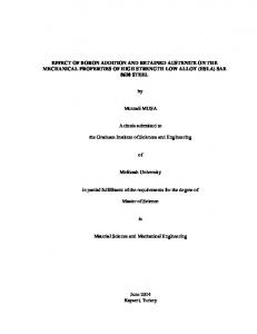
2.1 Hardness The hardness dependence of the alloy on Cr content is shown in Figure 2.1.Various percentages of Cr added is shown in the figure. In as cast condition there is not a very significant effect of Cr on the hardness. It is seen that for 0.1% addition of Cr highest hardness upon aged condition is achieved and further addition of Cr reduces the hardness. The hardness dependence on the alloy with Cr content is also shown. In as cast condition there is not a very significant effect of Cr on the hardness. Solution treatment and aging increase the hardness of the alloys as compared to as cast condition. The role played by Cr is consistent with in behaving as a solid solution strengthener.[8]
Figure 2.1 Hardness variations with Cr addition
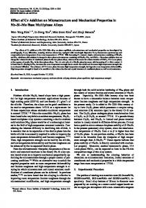
2.2 Tensile Strength Figure 2.2 shows the variation in the ultimate tensile strength for various treatments and varying Cr contents. Even the yield strength varies in a similar way. This result is consistent with pattern observed on the tensile strength of Al alloys. The ductility was found to continuously decrease with the addition of Cr, but the effect of heat treatment has no adverse effect on the ductility.
7
Figure 2.2 UTS variations with Cr additions
8
CHAPTER 3
EFFECT OF RARE EARTH METAL ON ALUMINIUM ALLOY
3.1 MODIFIERS Need of Grain Modifiers: Microstructure for A356 alloy on eutectic point is-
FIGURE 3.1 MICROSTRUCTURE OF A356 ALLOY ON EUTECTIC POINT
Here the sharp edges of needle type structure of Si in Aluminium results in less strength and failure of the object. So we have to modify it. This type of material we can’t use in automobile.
Similarly when we move on to hypo-eutectic and hyper-eutectic mixture of this alloy we find that the uneven distribution of Si in Al occurs and it results in fatigue failure of material.
9
In detail those are following: 1. In Hypo-Eutectic: Here the Si has lower distribution so tougher than other two. So refining of the microstructure we have to modify it by either stirring or using a modifier element. 2. In Hyper-Eutectic: However, all of the aforementioned desirable properties of hypereutectic Al-Si alloys depend on the characteristics of their cast microstructures, namely secondary dendrite cell size or arm spacing, and the size, morphology (or shape), and distribution of eutectic and primary Si particles. The morphology of primary silicon particles can be rather complex, such as plate-like, star-shaped, polygonal, blocky, and feathery varying with solidification conditions, chemical composition, and alloying elements.
In these forms, primary silicon particles compromise the machinability, wear resistance, and mechanical properties of the alloy castings. Refinement and control of the eutectic and primary silicon particles is an effective way of improving the properties of the hypereutectic Al-Si alloys. So here arises the need to use some process to refine the grains or to modify these. Thinking in this regard we feel the need to go for grain refinement or/and modification.
3.2 GRAIN REFINERS
Need of Grain Refiners-
Grain refinement, owing to its good capacity of improving uniform mechanical properties, had attracted volumes of literatures since 1950s. Most of these studies pay more attentions on refinement mechanisms or fading mechanisms of refiner itself. In unmodified A356 alloy, the main eutectic reaction occurs at 5740 ֩C as a binary reaction, which results in coarse irregular plate-like silicon. The final microstructure is largely determined by the eutectic reaction. Unmodified eutectic silicon is present as coarse polyhedral particles and consequently the casting
10
exhibits poor mechanical properties. Grain refinement, owing to its good capacity of improving uniform mechanical properties, had attracted volumes of literatures since 1950s.
Most of these studies pay more attentions on refinement mechanisms or fading mechanisms of refiner itself. Although chemical modifiers such as sodium and strontium significantly improve certain casting characteristics, they have other undesirable effects. The modification of eutectic silicon is of general interest since fine eutectic silicon along with fine primary Aluminium grains improves mechanical properties and ductility.
Chemical modification has been widely used in industry for producing A356 alloy. Modification with Na, Sr and Sb changes the silicon morphology. This is achieved by rapid solidification, chemical modification and thermal modification in the solid state. Na, Sr and Sb are commonly used for chemical modification and addition of small amounts of these elements to the melt changes the coarse and large needles of silicon into a fine and well-rounded form. It is well known that on solidification of hypoeutectic Al-Si alloys the primary α- Al solidifies with coarse columnar or twinned columnar Aluminium and modification changes Silicon morphology. Thus, keeping in view, an attempt has been made to study the effect of minor additions of Ti, B and Sr in the form of master alloys on the microstructure and mechanical properties of A356 alloy either individually or in combinations.
3.3 RARE EARTH ELEMENTS A rare earth element (REE) or rare earth metal (REM), as defined by IUPAC, is one of a set of seventeen chemical elements in the periodic table, specifically the fifteen lanthanides, as well as scandium and yttrium. Scandium and yttrium are considered rare earth elements because they tend to occur in the same ore deposits as the lanthanides and exhibit similar chemical properties. Any of a group of chemically similar metallic elements comprising the lanthanide series and (usually) scandium and yttrium. They are not especially rare, but they tend to occur together in nature and are difficult to separate from one another.
11
FIGURE 3.2 PERIODIC TABLE SHOWING RARE EARTH ELEMENTS
Rare earth elements are •
cerium (Ce)
•
dysprosium (Dy)
•
erbium (Er) 12
•
europium (Eu)
•
gadolinium (Gd)
•
holmium (Ho)
•
lanthanum (La)
•
lutetium (Lu)
•
neodymium (Nd)
•
praseodymium (Pr)
•
promethium (Pm)
•
samarium (Sm)
•
scandium (Sc)
•
terbium (Tb)
•
thulium (Tm)
•
ytterbium (Yb)
•
yttrium (Y)
3.4 EFFECT OF RARE EARTH ADDITION ON ALUMINIUM ALLOYS It is well known that the effect of rare earth (RE) and transitional elements in Al alloys is very evident. The character of RE elements determines their effect in Al alloys. Because of their large atomic radius and tendency to lose two outermost level s-electrons and a 5d or 4f electron to become trivalent ion, RE metals are very active in chemical reaction. They can react easily to the gas, impurity and matrix in the Al alloys serving as de-aeration and de-slag. At the same time, the compound with rare earth which is stable and high-melting can change the structure of Al alloy and improve their properties. Because it's outer second level d13
electron is incomplete, Zr has many valence electrons. A part of electrons form metallic bond and others form covalent bond with the valence electrons of other elements which get into its lattice. Then the particles in the lattice combine more tightly which makes the compound have higher stability, hardness, melting and boiling point. So the RE and Zr element can serve as alloy element in Al alloys and other metals.
FIGURE 3.3 MICROSTRUCTURE OF A356 ALLOY As-CAST
14
FIGURE 3.4 MICROSTRUCTURE OF ALLUMINIUM ALLOY WITH RARE EARTH ADDITION
The effect of RE in Al alloys can be described as follows: •
RE can decrease the harm of hydrogen in the Al and its alloys through heightening its solid solubility and forming stable RE hydride.
•
RE is a kind of perfect modifier. It has better stability and lower gas pickup tendency than traditional modifier.
•
RE changes the needle like structure of the aluminium alloy to fine globular structure.
•
RE can improve the hardness of Al alloys because RE can react easily to Al and form high melting point and infusible compound which disperse in the alloy. So the grains are refined and grain boundary is strengthened.
15
•
RE can improve the corrosion resistance property of the alloy. On one hand, RE sharpens the anodic polarization curve and reduces the corrosion electric current. On the other hand, RE intermetallic compound can resist the dispersion of oxygen and lower the oxidizing speed.
•
RE changes the structure (such as grain refining, improve grain orientation and proper secondary phase distribution) as well as yield strength, plasticity, mechanical property, working property, electric conductivity, heat conductivity and optic property of the alloys.
16
CHAPTER 4
SAMPLE PREPARATION
4.1 CASTING Aluminium chromium alloys with minor additions were prepared in a stir casting electric furnace by melting electrolytically pure aluminium under insulating flux Cover. The requisite amount of modifiers and minor alloying elements are added to the melt and allowed to mix properly. Then melt is poured into the mould to get the desired cast samples.
FIGURE 4.1 STIR CASTING FURNACE
17
Furnace specifications – •
Function – Melting cum sintering
•
Heating element – SiC
•
Achievable peak temperature - 1450 °C
•
Volumetric capacity - 150 mm x 150 mm x 200 mm
Furnace features – •
Programmable Temp Controller
•
RS232C Serial Computer Interface
•
Sintering system with digital rpm
•
Vibration-less motorized hearth
FIGURE 4.2 ALUMINIUM ALLOY INGOT
18
Aluminium ingot was cut into small pieces and the pieces were weighed according to the requisite concentration of aluminium alloy in the sample. The stir casting furnace was firstly preheated to a temp of 750°C and the weighed pieces were then put into the crucible and kept in the furnace. The temperature of the furnace falls below 750°C so its temperature was raised slowly to 750°C. The melt was kept at 750°C for almost 1 hour for uniform composition throughout the melt and for proper mixing of modifiers and minor alloying elements. Rare earth elements were added during the course of melting as modifiers and chromium was added to the melt as minor alloying element. Chromium addition Requisite quantity of chemically pure chromium powder was compacted with the aluminium. Chromium powder was weighed and requisite amount was wrapped in aluminium foil and these foils were plunged into the melt. The alloy was then stirred using a mechanical stirrer with lime coating. The melt was stirred to get uniform composition throughout the melt and the melt was then degassed.
FIGURE 4.3 MECHANICAL STIRRER WITH LIME COATING
19
Rare earth addition – Rare earth additions were made in the course of melting, by wrapping them inside the aluminium foils. Rare earth metal powder was weighed and requisite amount of the powder was wrapped in aluminium foil and these foils were plunged into the melt. The alloy was then stirred using a mechanical stirrer with lime coating. The melt was stirred to get uniform composition throughout the
melt
and
the
melt
was
then
degassed
by
addition
of
degassifiers.
Mould preparation – Mould was scrubbed properly to remove dust particles and impurities from the mould faces and the runner. Mould was then preheated on the furnace in the smithy shop. Mould was usually preheated for 15 to 20 min, then both the faces of the mould were clamped together and were held together tightly into a clamp vise. Graphite powder was sprinkled on the mould faces and the runner before clamping was done. Sprinkling was done for easy removal of cast samples from the mould.
FIGURE 4.4 CAST IRON MOULD ( 160 mm long and 20 mm diameter)
20
FIGURE 4.5 CAST IRON MOULD (250 mm long, 10mm diameter in middle and 20 mm diameter at both ends)
21
After addition of minor alloying elements and modifiers the temperature of the of the furnace falls below 750°C so its temperature was raised slowly to 750°C. The melt was kept at 750°C for almost 1 hour for uniform composition throughout the melt and for proper mixing of modifiers and minor alloying elements. Hexachloro-ethane (degassifier) and slag former powder were added to the melt and the slag formed was removed using a skimmer. The melt was then poured into 160 mm long cylindrical mould having diameter 20mm, which was clamped into the clamping vise. The melt was allowed to solidify and the cast samples were collected.
FIGURE 4.6 MELT POURED IN THE MOULD WHICH IS CLAMPED IN THE VISE
22
SAMPLES PREPARED – 1. Aluminium alloy with no addition 2. Aluminium alloy with rare earth addition 3. Aluminium alloy with chromium addition 4. Aluminium alloy with chromium addition 5. Aluminium alloy with chromium and rare earth addition 6. Aluminium alloy with chromium and rare earth addition
FIGURE 4.7 ALUMINIUM ALLOY CAST SAMPLES
23
The following table shows the chemical composition of the samplesSAMPLE NUMBER
ALLUMINIUM ALLOY % ( by weight)
CHROMIUM
RARE EARTH
% ( by weight)
% ( by weight)
1
100.0
0.0
0.0
2
99.5
0.0
0.5
3
99.5
0.5
0.0
4
99.0
1.0
0.0
5
99.0
0.5
0.5
6
98.5
1.0
0.5
TABLE 4.1 CHEMICAL COMPOSITION OF THE SAMPLES
24
Chapter 5
Tensile Testing
Ultimate tensile strength (UTS), often shortened to tensile strength (TS) or ultimate strength, is the capacity of a material or structure to withstand loads tending to elongate, as opposed to compressive strength, which withstands loads tending to reduce size. In other words, tensile strength resists tension (being pulled apart), whereas compressive strength resists compression (being pushed together). Ultimate tensile strength is measured by the maximum stress that a material can withstand while being stretched or pulled before breaking. Some materials break very sharply, without plastic deformation, in what is called a brittle failure. Others, which are more ductile, including most metals, experience some plastic deformation and possibly necking before fracture. The tensile tests were conducted on Universal Tensile Machine at room temperature. The samples were prepared according to ASTM E8. The tensile properties of the alloys were determined by performing the tension test on standard cylindrical tensile specimens. Before to testing, the surface of the specimens was finished by using 400 grid emery sheets. A typical tensile specimen as per ASTM standard is shown in Fig 5. Lo = Gauge length Lc = Parallel length r = Transition radius So = Original cross section area d =gauge length diameter
Figure 5.1 Tensile Strength Specimen
25
5.1 Tensile Specimen A tensile specimen is a standardized sample cross-section It has two shoulders and a gauge in between. The shoulders are large so they can be readily gripped, whereas gauge section has a smaller cross section so that the deformation and failure can occur in this area.
Figure 5.2 Specimen with Specification
5.2 Process The test process involves placing the test specimen in the testing machine and applying tension to it until it fractures. The data is manipulated so that it is not specific to the geometry of the test sample. The elongation measurement is used to calculate the engineering strain, using the following equation: ε = ΔL / Lo = (L-Lo) / Lo σ=F/A
Where ΔL is the change in gauge length, Lo is the initial gauge length, and L is the final length. The force measurement is used to calculate the engineering stress, a, using the following equation where F is the force and A is the cross-section of the gauge section. The machine does
26
these calculations as the force increases, so that the data points can be graphed into a stress-strain curve. The steps involved are: •
Step 1: Original shape and size of the specimen with no load.
•
Step 2: Specimen undergoing uniform elongation.
•
Step 3: Point of maximum load and ultimate tensile strength.
•
Step 4: The onset of necking (plastic instability).
•
Step 5: Specimen fractures.
•
Step 6: Final length.
Figure 5.3 Steps involved in tensile testing
27
Figure 5.4 Stress-Strain Graph as per U.T.M
The quality index was used in this work to allow comparison of different compositions. The quality index relates the ductility (elongation) and ultimate tensile strength into a single term. It was originally developed by DROUZY et al. CACERES et al showed the fundamental basis of the quality index. The quality index (specifically for alloys A356/7) is given by Eq.1: I =σ+150 log y ………………………………………………………………………………..(1) where I is the quality index, MPa; σis ultimate tensile strength, MPa; y is the elongation, %. Quality Index of A356 with 0.5% is best while for A356 with 0.5% Cr and 0.5% RE is worst.
28
Sr. No.
Composition (wt. %)
Tensile Strength
Quality Index
(MPa)
(MPa)
1.
Base Metal A356
146
2.
A356 + 0.5% Cr
155
254.84
3.
A356 + 1.0% Cr
117
135.08
4.
A356 + 0.5% Rare Earth 149
194.15
Metal 5.
A356 + 0.5% Cr + 0.5% 80
116.08
RE 6.
A356 + 1.0% Cr + 0.5% 122 RE Table 5.1 Tensile Strength
29
65.49
30
31
32
33
34
35
36
37
38
5.3 Results The effects of impurities such as chromium and modifier rare earth metal on the microstructure and mechanical properties of an A356 die casting alloy are investigated. The results indicate that the area fraction and the size of brittle α-Alx (Fe, Mn, Cr)y Siz intermetallic compounds increase by increasing the Cr content, and this affects the ultimate tensile strength and the ductility of the alloy at higher Cr level. U.T.S has been increased on adding Cr upto 0.5% but on further adding Cr upto 1.0%, it’s U.T.S. decreases. By the further addition of 0.5% rare earth to the 1% Cr aluminium alloy, the U.T.S. increases but still the U.T.S. is less than that of 0.5% Cr aluminium alloy.
39
Chapter 6
Hardness Testing
Hardness is the measurement of the resistance of a metal to plastic deformation. The process for checking the hardness of a material may vary but it usually consists of the use of an indentation that is measured in a casting. Hardness is the property that shows a materials ability to resist permanent deformation when it is under load. The greater the hardness of a material the greater the material will resist deformation. For Metallurgists, Hardness Testing is a collection of different methods for measuring a definite characteristic of metallic materials, namely: a) The resistance to penetration of a specific Indenter (defined by fixed form and properties), b) Under the application of a certain static force c) For a definite time, d) Using precise measuring procedures.
6.1 Rockwell cum Brinell hardness Testing Machine Rockwell Cum Brinell Hardness Testing Machine used to measure hardness of metals & alloys of all kinds, hard or soft, whether round, flat or irregular in shapes. Rockwell Cum Brinell Hardness Testing Machine is ideally suitable for laboratories, tool rooms, Heat treatment shops, R&D
departments, inspection departments, casting & forging industries, educational
institutions. Brinell hardness is also checked on non-ferrous materials like Cast iron, Alluminium, etc. Automatic weight selection with automatic zero setting dial gauge. The machines are built with fully enclosed CAST IRON body. These are SEASONED & precisely calibrated for accuracy. The special CLAMPING CONE holds the job firmly and avoids slipages. This also protects the INDENTORS. The dial gauge is covered by transparent glass cover. It protects from dust & damages. The loading is by square threaded screw & unloading is by eccentric lever while penetration is Hydraulic.
40
6.2 ALZ B-250: * Automatic load selector provided at right side of the machine * Automatic zero setting type dial gauge * 60, 100, 150 & 187.5 kgf major load * To check Rockwell scale and BRINELL scale with ball Dia. 2.5 mm & 187.5 kgf load.
6.2.1 STANDARD ACCESSORIES: 1. One dial gauge Dia. 80 mm. 2. One flat table Dia. 50 mm. 3. One Vee grooved table for cylindrical job Dia. 6 mm to 45 mm. 4. One Diamond indenter with 120° cone angle. 5. One test block master for Rockwells “C” scale 6. One ball indenter 1/16” dia. 7. One test block for Rockwell “B” scale 8. An Allen key 3/32” and 5/32”. 9. A set of telescopic sleeve for screw protection. 10. One set of weight, 60, 100 & 150 kgf. Cast Iron. 11. Accessories kit Box for above accessories. 12. One test block master HB & 187.5 kgf. load. 13. One ball indenter 2.5mm. Dia. 14. One BRINELL Microscope. 15. One instruction Manual.
41
Figure 6.1 Rockwell cum brinell hardness machine
Figure 6.2 Rockwell cum brinell hardness testing machine
42
6.2.2 Rockwell Scales Rockwell hardness values are expressed as a combination of a hardness number and a scale symbol representing the indenter and the minor and major loads. The hardness number is expressed by the symbol HR and the scale designation. There are 30 different scales. The majority of applications are covered by the Rockwell C and B scales for testing steel, brass, and other metals. However, the increasing use of materials other than steel and brass as well as thin materials necessitates a basic knowledge of the factors that must be considered in choosing the correct scale to ensure an accurate Rockwell test. The choice is not only between the regular hardness test and superficial hardness test, with three different major loads for each, but also between the diamond indenter and the 1/16, 1/8, 1/4 and 1/2 in. diameter steel ball indenters. For soft materials such as copper alloys, soft steel, and aluminum alloys a 1/16" diameter steel ball is used with a 100-kilogram load and the hardness is read on the "B" scale. In testing harder materials, hard cast iron and many steel alloys, a 120 degrees diamond cone is used with up to a 150 kilogram load and the hardness is read on the "C" scale. There are several Rockwell scales other than the "B" & "C" scales, (which are called the common scales). A properly reported Rockwell value will have the hardness number followed by "HR" (Hardness Rockwell) and the scale letter. For example, 50 HRB indicates that the material has a hardness reading of 50 on the B scale. If no specification exists or there is doubt about the suitability of the specified scale, an analysis should be made of the following factors that control scale selection: 1. Type of material 2. Specimen thickness 3. Test location 4. Scale limitations
43
Table 6.1 Rockwell Hardness Scales
Typical Application of Rockwell Hardness Scales HRA . . . . Cemented carbides, thin steel and shallow case hardened steel HRB . . . . Copper alloys, soft steels, aluminium alloys, malleable irons, etc HRC . . . . Steel, hard cast irons, case hardened steel and other materials harder than 100 HRB HRD . . . . Thin steel and medium case hardened steel and pearlitic malleable iron HRE . . . . Cast iron, aluminium and magnesium alloys, bearing metals
44
HRF . . . . Annealed copper alloys, thin soft sheet metals HRG . . . . Phosphor bronze, beryllium copper, malleable irons HRH . . . . Aluminium, zinc, lead HRK . . . . } HRL . . . . } HRM . . . .} . . . . Soft bearing metals, plastics and other very soft materials HRP . . . . } HRR . . . . } HRS . . . . } HRV . . . . } Here in this project as we are using aluminum alloys so we are using 1\16’ steel ball indenter and a short cylindrical specimen of any diameter and height.
Figure 6.3 1\16” steel ball indenter
Figure 6.4 Hardness Specimen
45
6.3 Process The Rockwell cum brinell hardness test method consists of indenting the test material with a diamond cone or hardened steel ball indenter. The indenter is forced into the test material under a preliminary minor load F0 (Fig. 1A) usually 10 kgf. When equilibrium has been reached, an indicating device, which follows the movements of the indenter and so responds to changes in depth of penetration of the indenter is set to a datum position. While the preliminary minor load is still applied an additional major load is applied with resulting increase in penetration (Fig. 1B). When equilibrium has again been reach, the additional major load is removed but the preliminary minor load is still maintained. Removal of the additional major load allows a partial recovery, so reducing the depth of penetration (Fig. 1C). The permanent increase in depth of penetration, resulting from the application and removal of the additional major load is used to calculate the Rockwell hardness number.
6.3.1 Principe of the Rockwell cum Brinell Test 1. The indenter moves down into position on the part surface 2. A minor load is applied and a zero reference position is established 3. The major load is applied for a specified time period (dwell time) beyond zero 4. The major load is released leaving the minor load applied
Figure 6.5 Rockwell cum brinell hardness principle
46
The resulting Rockwell number represents the difference in depth from the zero reference position as a result of the application of the major load.
Sr. No.
Composition (wt. %)
Hardness Number
1.
Base Metal A356
24
2.
A356 + 0.5% Cr
18
3.
A356 + 1.0% Cr
21
4.
A356 + 0.5% Rare Earth Metal
22
5.
A356 + 0.5% Cr + 0.5% RE
18
6.
A356 + 1.0% Cr + 0.5% RE
23
Table 6.2 Hardness Number for different specimen
Conversion of Rockwell to Brinell Hardness There is no accurate conversion tables and equations, but dandong foundry recommend the following formulas and comparison tables according to the experience and standards.
47
Conversion Table Sr. No.
Rockwell Hardness Number
Brinell Hardness Number
1.
24
248
2.
18
212
3.
21
231
4.
22
237
5.
18
212
6.
23
243
6.4 Results There is a decrease in hardness by addition of chromium. This is due to porosity in cast due to alloy element addition process. By the addition of rare earth metal the decrease in hardness due to porosity is decreased. Rare earth can improve the hardness of aluminum alloy because RE can easily react with aluminum and form high melting point and infusible compound which disperse in the alloy and decrease porosity. So the grains are refined and grain boundaries are strengthened.
48
Chapter 7
Toughness Testing
7.1 CHARPY IMPACT TEST The Charpy impact test, also known as the Charpy V-notch test, is a standardized high strain-rate test which determines the amount of energy absorbed by a material during fracture. This absorbed energy is a measure of a given material's notch toughness and acts as a tool to study temperature-dependent ductile-brittle transition. It is widely applied in industry, since it is easy to prepare and conduct and results can be obtained quickly and cheaper. Charpy impact test of metals provides information on failure mode under high velocity loading conditions leading sudden fracture where a sharp stress raiser (notch) is present. The energy absorbed at fracture is generally related to the area under the stress-strain curve which is termed as toughness in some references. Brittle materials have a small area under the stress-strain curve (due to its limited toughness) and as a result, little energy is absorbed during impact failure. As plastic deformation capability of the materials (ductility) increases, the area under the curve also increases and absorbed energy and respectively toughness increase. Similar characteristics can be seen on the fracture surfaces of broken specimens. The fracture surfaces for low energy impact failures, indicating brittle behaviour, are relatively smooth and have crystalline appearance in the metals. On the contrary, those for high energy fractures have regions of shear where the fracture s urface is inclined about 45° to the tensile stress, and have rougher and more highly deformed appearance,
called fibrous fracture. Although two standardized tests, the Charpy and Izod, were designed and used extensively to measure the impact energy, Charpy v-notched impact tests are more common in practice. The apparatus for performing impact tests is illustrated schematically.
7.1.1 Procedure The load is applied as an impact blow from a weighted pendulum hammer that is released from a position at a fixed height h. The specimen is positioned at the base and with the release of pendulum, which has a knife edge, strikes and fractures the specimen at the notch. The pendulum continues its swing, rising a maximum height h' which should be lower than h naturally. The
49
energy absorbed at fracture can be obtained by simply calculating the difference in potential energy of the pendulum before and after the test such as, E=m.g. (h-h ') Where m is the mass of pendulum and g is the gravitational acceleration.
Fig 7.1 Charpy impact testing machine
If the dimensions of specimens are maintained as indicated in standards, notched-bar impact test results are affected by the lattice type of materials, testing temperature, thermo-mechanical history, chemical composition of materials, degree of strain hardening, etc.
50
7.1.2. Sample specification According to ASTM A370, the standard specimen size for Charpy impact testing is 10 mm × 10mm × 55mm.
Fig 7.2. Charpy specimen specification
7.2 OBSERVATIONS Sample size- 10 x 10 x 55mm Notch size - 10 x 5 x 2.5 mm Notch area - 10 x 5 mm SAMPLE.NO
COMPOSITION
INITIAL (Kg.m)
FINAL
CHARPY
(Kg.m)
IMPACT VALUE (Kg m/ cm2)
1.
Al 356
21.4
16.2
10.4
2.
Al 356 + 0.5 % rare earth
21.4
16
10.8
metals 3.
Al 356 + 0.5 % Cr
21.4
16
10.8
4.
Al 356 + 1 % Cr
21.4
16.4
10
5.
Al 356 + 0.5% Cr + 0.5
21.4
15.6
11.6
21.4
16.2
10.4
rare earth metal 6
Al 356 + 1 % Cr + 0.5 % rare earth metal
Table 7.1 Charpy impact value for different specimen
51
7.3 Result The toughness of the material is decreasing with addition of Chromium. Generally, the toughness increases with chromium addition due to the fibrous structure formed by the chromium addition, so the decrease observed here is due to the porosity in the casting. It is also seen that toughness increases with addition of RE. This is due to decrease in porosity caused by addition of RE. Maximum Toughness is found in the alloy containing 0.5% Cr and 0.5% RE.
52
Chapter 8
Corrosion Test
Aluminum has an economic and industrial importance due to lightweight, high thermal and electrical conductivity. The resistance of aluminum against corrosion in aqueous media can be attributed to a rapidly formed compact, strongly adherent and continuous oxide film Therefore, aluminum and its alloys are widely used in many industries such as reaction vessels, pipes, machinery and chemical batteries. Hydrochloric acid solutions are used for pickling, chemical and electrochemical etching of aluminum Moreover, the presence of aggressive ions like chloride creates extensive localized attack. Because of the general aggressive acid solutions, inhibitors are commonly used to reduce the corrosive attack on metallic materials.
Fig 8.1 specimens in 0.1N HCl solution .The solution is prepared using 0.1 normal HCl and the samples were soaked in to it for a period of 96 hours. After this the specimens are cleaned with H2O and rinsed with acetone and weight is checked in an electronic weighing machine. Following formula can be used to calculate the percentage of corrosion rate.
53
Corrosion Rate (CR) =
Weight loss(g) ∗ K g Alloy Density (cm3) ∗ Exposed Area (A) ∗ Exposure Time (hr)
The constant can be varied to calculate the corrosion rate in various units: Desired Corrosion Rate Unit (CR)
Area Unit (A)
K-factor
mils/year(mpy)
in2
5.34*105
mils/year(mpy)
cm2
3.45*106
millimeters/year(mmy)
cm2
8.75*104
Table 8.1 value of K for Corrosion rate Metal Loss (ML) =
Weight loss (g) ∗ K g Alloy Density (cm3) ∗ Exposed Area (A)
Desired Metal Loss (ML)
Area Unit (A)
K-factor
Mils
in2
5.34*105
Mils
cm2
3.45*106
millimeters
cm2
8.75*104
Table 8.2 value of K for metal loss
Sample no. 1 2 3 4 5. 6.
Composition
Initial weight
Final weight
Mass loss
Al 356 Al 356 + 0.5 rare earth Al 356 + 0.5% Cr Al 356 + 1 %Cr Al 356 +0.5%Cr + 0.5 % rare earth Al 356 +1%Cr +0.5%rare earth
9.0126 8.8374 9.2262 10.0470 11.5636
8.9645 8.7934 9.1818 9.9604 11.5099
0.0481 0.044 0.044 0.0866 0.0537
9.9738
9.9964
Mass gained
Table 8.3 Observation of initial and final mass for corrosion test(48hrs)
54
Sample
Sample composition
Density(g/cc)
no
Exposed
Weight
Corrosion
Metal
area(cm2)
loss(g)
rate(millimeter/year)
loss(millimeter)
1
A356
2.594
13.194
0.0481
2.56
0.0140
2
A356+0.5% RE
2.544
13.194
0.044
2.389
0.0131
3
A356+0.5%Cr
2.656
13.194
0.044
2.288
0.0125
4
A356+1%Cr
3.019
12.881
0.0866
4.054
0.0222
5
A356+0.5%Cr+0.5RE
3.181
13.823
0.0537
2.3195
0.01272
Table 8.4 value of corrosion rate and metal loss for different specimen( 48 hrs)
8.1 Results We observe a decrease in corrosion rate which mean increase in corrosion resistance by addition of 0.5% rare earth elements, 0.5% Chromium and further increase in corrosion resistance by addition of mixture of 0.5% Chromium and 0.5% rare eath elements. There is a increase of corrosion rate by addition of 1% Chromium. There is negative corrosion rate or there is a mass gain by the specimen, which may be due to formation of Chromium oxide formation in the presence of rare earth elements.
55
Chapter 9
Microstructural Characteristics
9.1 PREPARATION OF SPECIMEN FORMICROSTRUCTURIAL PROPERTIES Proper preparation of metallographic specimens to determine microstructure and content requires that a rigid step-by-step process be followed. In sequence, the steps include sectioning, course grinding, fine grinding, polishing, etching and microscopic examination. Specimens must be kept clean and preparation procedure carefully followed to reveal accurate microstructures.
1. Sectioning Parting off the specimen from the workpiece which is going to be observed for microstructure is called sectioning. Section is done on lathe machines.
2. Course grinding The purpose of the coarse grinding stage is to generate the initial flat surface necessary for the ubsequent grinding and polishing steps. As a result of sectioning and grinding, the material may get cold worked to a considerable depth with a resultant transition zone of deformed material between the surface and the undistorted metal. Course grinding can be accomplished either wet or dry using 80 to 180 grit electrically powered disks or belts, but care must be taken to avoid significant heating of the sample. The final objective is to obtain a flat surface free from all previous tool marks and cold working due to specimen cutting.
3. Fine grinding Fine Grinding of metallurgical samples is closely allied with the Coarse Grinding which precedes them. Each stage of metallographic sample preparation must be carefully performed; the entire process is designed to produce a scratch free surface by employing a series of successively finer abrasives. Failure to be careful in any stage will result in an unsatisfactory sample. Movement from one stage to the next should only proceed when all of the scratches from the preceding stage are completely removed. In general, successive steps are 120, 400, 800, 1000 and 1500 grit SiC and the grinding rate should 56
steadily decrease from one stage to the next. Proper grinding involves the rotation of the sample between stages while the grinding angle must be held constant during the grinding at any on stage.
4. Polishing Polishing involves the use of abrasives, suspended in a water solution, on a cloth-covered electrically powered wheel. Diamond abrasives provide the best, and most expensive, compounds utilized in polishing; standard sized aluminum oxide powders are applied for general use purposes. Following the final 600 grit fine-grinding stage, the sample MUST be washed and carefully dried before proceeding to the first polishing stage! At the polishing stages, even hard dust particles in the air which settles on the polishing cloth can cause unwanted scratching of the specimen! Careful washing of the specimen and the operator's hands must be carried out prior to each stage of polishing! Beginning with 25micron suspended aluminum oxide particles (suspended in water) on a Nylon-cloth, the final fine-grinding surface layer resulting from the previous grinding procedure should be completely removed with a rotation rate of 150-200 rpm. The specimen is initially held at one position on the wheel, without rotation, until most of the previous grinding marks are removed. It can be rotated slowly, counter to the wheel rotation, until only scratches from the 25- micron aluminum oxide are visible. During the initial polishing stage, moderate pressure can be applied to the specimen and the entire stage should generally take 1 or 2 minutes!
Figure 9.1 Double disk polishing machine
57
5. Etching Microscopic examination of a properly polished, unetched specimen will reveal only a few structural features such as inclusions and cracks or other physical imperfections. Etching is used to highlight, and sometimes identify, microstructural features or phases present. Even in a carefully prepared sample, a surface layer of disturbed metal, resulting from the final polishing stage, is always present and must be removed. Etchants are usually dilute acid or dilute alkalis in a water, alcohol or some other solvent. Etching occurs when the acid or base is placed on the specimen surface because of the difference in rate of attack of the various phases present and their orientation. The etching process is usually accomplished by merely applying the appropriate solution to the specimen surface for several seconds to several minutes. For aluminum alloys, we use solution of 1ml hydrofluoric acid in 99ml of water.
Figure 9.2 Upper view of specimen
58
Figure 9.3 Side view of specimen
9.2 INVERTED METALLURGICAL MICROSCOPE This microscope is used for microscopic view of the microstructure formed. The image formed is 100 times larger than their actual size.
Figure 9.4 Inverted Metallurgical Microscope
59
9.3 MICROSCOPIC EXAMINATION Initial microscopic viewing should be done utilizing a stereomicroscope, which reveals a threedimensional scanning of the specimen surface. The specimen is placed on the stage of the microscope so that its surface is perpendicular to the optical axis. Detailed viewing is done with a Metallurgical Microscope. A metallurgical microscope has a system of lenses (objectives and eyepiece) so that different magnifications (25X to 1000X) can be achieved. The important characteristics of the microscope are: (1) magnification, (2) resolution and (3) flatness of field. The resultant magnification is the product of the magnifying power of the objective and that of the ocular.
9.4 MICROSTRUCTURAL TESTING Microstructure is defined as the structure of a prepared surface or thin foil of material as revealed by a microscope above 25× magnification. The microstructure of a material can strongly influence physical properties such as strength, toughness, ductility, hardness, corrosion resistance, high/low temperature behavior, wear resistance, and so on, which in turn govern the application of these materials in industrial practice. The concept of microstructure is perhaps more accessible to the casual observer through micro structural features in commonplace objects. If one ever comes across a piece of galvanized steel, such as the casing of a lamp post on road divider, one observes that the surface is not uniformly colored, but is covered with a patchwork of interlocking polygons of different shades of grey or silver. Each polygon (the most frequently occurring would be hexagons) is a single crystal of zinc adhering to the surface of the steel beneath. Zinc and lead are two common metals which form large crystals visible to the naked eye. The metallic atoms in each crystal are well organized into one of seven crystal lattice systems possible for metals (cubic, tetrahedral, hexagonal, monoclinic, triclinic, rhombohedra, and orthorhombic); these systems dictate that the atoms are all lined up like points in a 3-D matrix. However, the direction of alignment of the matrices differ from crystal to adjacent crystal, leading to variance in the reflectivity of each presented face of the interlocked crystals on the galvanized surface. Symmetrical crystals are generally unstressed, unworked. They grow in all directions equally and were not subjected to deforming stresses either during or after. For large crystals, the ratio of crystal bulk to inter-crystal boundary (more properly, intra-granular 60
boundary) is high. This indicates high ductility but correspondingly, lower strength, but a true study would take into quantitative account the relative strengths of the crystal and that of intercrystal bonding.
9.5 BENEFITS OF CHROMIUM ADDITION The main benefit of adding Cr to Al-Mg, Al-Mg-Si and Al-Mg-Zn group alloys is the formation of fine dispersed phases that prevent grain growth and recrystallization. As a common addition to neutralize the effects of Fe, the action of Cr is likely to be analogous to that of Mn, in that the equilibrium distribution of phases is probably altered to promote the formation of K-Fe [42]. The addition of Cr causes the formation of very coarse complex compounds with other impurities such as Fe in those alloys commonly used in the pressure-die-casting industry. The formation, growth and sedimentation of these multicomponent particles can lead to a depletion of Fe concentration, generally accepted to be beneficial to casting quality.
9.6 ANALYSIS OF RESULT 1. The structure having sharp and discontinuous small needle type dendrites
Figure 9.5 Base Metal A356
61
2. The modifiers produce the blunt and somewhat globular needles which can be seen in the image above. This type of grain structure is considered to be great in terms of strength analysis. After rare earth addition to base alloy, the specimen produced by casting is seen with some blunt and small needles which consequently increase its properties upto a certain level.
Figure 9.6 A356 + 0.5% rare-earth
3. On addition of 0.5% chromium, the dendrites length increase
62
Figure 9.7 A356 + 0.5% Cr & .5 % rare earth
4. On adding 1.0% chromium, the dendrites become denser and size decreases.
Figure 9.8 A356 + 1.0% Cr & 0.5 % rare earth
5. The microstructure gets more continuous dendrites.
63
Figure 9.9 A356 + 0.5% chromium
6. The microstructure is more continuous and fibrous.
Figure 9.10 A356 + 1.0% chromium
64
9.7 MICRO-HARDNESS TESTING Hardness of the material towards deformation is determined by Indentation hardness test. Various such tests exist which can be carried out at macroscopic as well as microscopic scale, wherein the examined material is indented till an impression is formed. We are going to use Vickers’s hardness test for measuring micro hardness. The Vickers Ltd, developed this hardness test in 1921 as an alternative to the Brinell Hardness test to measure hardness of materials. [9] The Vicker’s test is often beneficial to use than other hardness tests as required calculations are independent of the size of the indenter, and the indenter can be used for any materials irrespective of hardness. The basic principle, as with all common measures of hardness, is to observe the concerned material’s ability to resist plastic deformation from a standard source. The Vicker’s test can be used for all metals and has one of the widest scales among hardness tests. The unit of hardness given by the test is known as the Vickers Pyramid Number (HV) or Diamond Pyramid Hardness (DPH).The hardness number can be converted into units of Pascal’s, but should not be confused with a pressure, which also has units of Pascal’s. The hardness number is determined by the load over the surface area of the indentation and not the area normal to the force, and is therefore not a pressure.
9.8 Vickers Hardness Test The Vickers hardness test method consists of indenting the test material with a diamond indenter, in the form of a pyramid with a square base and an angle of 136 degrees between opposite faces subjected to a test force of between 1gf and 100kgf. The full load is normally applied for 10 to 15 seconds. The two diagonals of the indentation left in the surface of the material after removal of the load are measured using a microscope and their average calculated. The area of the sloping surfaces of the indentation is calculated. The Vickers hardness is the quotient obtained by dividing the kgf load by the square mm area of indentation.
65
Figure 9.11 Vickers’s Micro Hardness Testing Machine
66
Figure 9.12 Pyramidal Indentation
F Load in kgf d Arithmetic mean of the two diagonals, d1 and d2 in mm HV Vickers hardness
When the mean diagonal of the indentation has been determined the Vickers hardness may be calculated from the formula. Modern digital Vickers hardness testers perform this calculation automatically and report the appropriate hardness result. 67
Several different loading settings give practically identical hardness numbers on uniform material, which is much better than the arbitrary changing of scale with the other hardness testing methods. The advantages of the Vickers hardness test are that extremely accurate readings can be taken, and just one type of indenter is used for all types of metals and surface treatments. The Vickers method is capable of testing the softest and hardest of materials, under varying loads. Table readings from Vickers micro hardness machine : Sr.
1
2
3
4
5
6
COMPOSITION
LOAD DIAGONAL DIAGONAL HARDNESS (gf)
D1(micron)
D2(micron)
(HV)
50
25.4
25.8
141
100
35.6
34.8
150
200
56.4
56.6
116
50
24.1
30.2
126
100
35.0
37.8
140
200
51.1
51.2
142
50
23.3
23.3
171
100
34.5
34.3
156
200
47.7
47.1
165
50
22.9
22.6
179
100
32.4
30.7
186
200
48.3
48.1
159
Al 356 + 0.5%
50
23.4
24.4
163
chromium & 0.5%
100
32.5
35.1
162
rare-earth
200
45.9
49.1
164
Al 356 + 1.0%
50
20.5
21.7
208
chromium & 0.5%
100
38.1
30.5
150
rare-earth metals
200
50.6
55.4
132
Al 356
Al 356 + 0.5% Rare-earth metals
Al 356 + 0.5% chromium
Al 356 + 1.0% chromium
Table 9.1 Microhardness reading for different specimen
68
AVG. HARDNESS
136
135.6
164.0
175.0
163.0
163.3
Figure 9.13 Al 356
Figure 9.14 Al 356 + Rare-earth metals
69
Figure 9.15 Al 356 + 0.5% chromium
Figure 9.16 Al 356 + 1.0% chromium
70
Figure 9.17 Al 356 + 0.5% chromium & 0.5% rare-earth
Figure 9.18 Al 356 + 1.0% chromium & 0.5% rare-earth metals
71
9.9 ANALYSIS OF MICRO HARDNESS •
Micro-hardness test analysis indicates that addition of chromium in A356 increases the micro hardness
•
Maximum increase in observed in case of 1.0% addition of chromium
•
As the addition of chromium as alloying element, the micro-hardness of A356 increases
•
However, 0.5% addition of rare-earth shows the least micro hardness
•
After mixing 0.5% of rare earth metals, there is a very small increase in the micro hardness as we increase the percentage of chromium addition.
•
The increase in micro-hardness is reflected in microstructure.
9.10 Conclusions Aluminum and its alloys can be prepared for testing microstructural properties using a straightforward four or five step procedure. Always section specimens with care to minimize the damage at the cut. Then, start grinding with the finest possible abrasive size that will remove the sectioning damage and get all the specimens in the holder to the same plane in a reasonable amount of time. The conclusions that are drawn from the results are: •
The microstructural properties increase on addition of rare-earth as modifier
•
On addition of alloying element dendrites become more continuous and increases micro hardness
•
On addition of rare-earth metals, microstructure become more globular and size of needles decreases.
•
Micro hardness is directly proportional to the size and length of dendrites.
72
CHAPTER 10
CONCLUSION
The effect of chromium and rare-earth metal in Al 356 was studied by adding them during casting process. The properties of different composition specimen of mixture of Al , Cr and rareearth metals were identified through different mechanical test and microstructure analysis. Addition of rare earth metal to Al 356 increases the mechanical properties and it also compensate for the losses in properties caused during the casting process. Addition of Cr show increase in mechanical properties for 0.5% and decrease for 1%. By the addition of both Cr and rare-earth metals together show variation from the alloys containing just Cr. Rare earth metals compensate the losses in properties caused by excessive addition(>0.5%) and also supports in increasing the properties for a alloy containing Cr