Journal of American Science
2010;6(9)
Effect of Joint Surface Contours on the Transverse and Impact Strength of Denture Base Resin Repaired by Various Methods. An In Vitro Study. Emiel A. Hanna*; Farhan Khalid Shah.2 and Ashraf A. Gebreel2 Prosthodontic Department, 6 October University, Cairo, Egypt. 2 Prosthodontics Department. College of Dentistry, King Khalid University Abha, Kingdom of Saudi Arabia *
[email protected] 1
Abstract: Aim of the study: This study investigated the transverse strength and estimate the impact resistance of repaired acrylic resin with different joints form reinforced with glass fibers and cured with different methods. Material and Method: Standard heat cure acrylic resin specimens were fabricated according to ADA specification No. 12 and were repaired with different methods. Repair was carried out by heat polymerization, auto polymerizing resin using pressure pot and auto polymerizing resin with glass fibers (with and without treatment by silane coupling agent). Samples were given different joint surface contour namely butt and 450 bevel. A total of 108 samples were prepared for this study. Transverse and impact strength were tested using Instron universal testing machine and Izod impact tester. Results: Irrespective of the method of repair, the transverse and impact strength of the test specimens decreased after repair except for the Group reinforced with glass fiber after treatment with silane coupling agent, having 450 bevel joint, tested for Impact strength which showed higher strength than the control. Conclusion: The transverse and impact strength values after repair were highest with auto polymerizing resin with glass fibers after treatment with silane coupling agent, having 450 bevel joint. [Journal of American Science 2010;6(9):115-125]. (ISSN: 1545-1003). Keywords: Joint Surface; Impact Strength; Denture Base Resin; Vitro Study. view of the different concepts as to which is the best method of preparing the interface of the fractured surface in order to obtain the strongest joint, the present study investigates the commonly used butt joint and 45 degree angled joint, with and without glass fiber reinforcement. This study is an effort to find the appropriate method which can provide the long lasting result and can prevent the recurrence of fracture.
1. Introduction Despite many advantages, methyl methacrylate is prone to fracturing. Therefore, fractures of the dentures are very frequent, almost equal to the number of newly made dentures (1). Acrylic denture base fracture is often a result of flexural fatigue and impact failure (2). Physical and mechanical properties of acrylic dentures can be enhanced by integration of different fibers with different fiber architectures into the denture base polymer (3-8). In order to improve flexural and impact strength of denture base polymer, graphite (6-10), glass (4, 11-15), and organic fibers, such as, aramide (15-18) and polyethylene fibers with high molecular weight (8, 18-26), are used. Today the most acceptable fibers for dental polymer reinforcements are glass fibers, because of their good aesthetics (5, 1113, 27, 28) and good bonding with polymers via silane coupling agents (29-31). Also, they can easily be adapted to the desired shape and length (32) which is then suitable for incorporation into denture base polymer material. Auto polymerizing resin, as a repair material, seems to produced better strength than visible light cure resins (33) and exhibited a repair strength similar to those found for conventional heat and microwave polymerized resins (34). Off course, one of the principal factors in the strength of a repair is the type of joint used in the repair. Various authors have advocated smooth and rough interface surfaces, butt joint (900), 45 degree angle joints,tapered, rounded and rabbeted joints and joints with mechanical retention (35,36). In
http://www.americanscience.org
2. Material and Methods For the purpose of this study, DPI Heat cure resin (Dental Product India), DPI Auto polymerizing resins (Dental Product India) and Glass fibers (Polydentia, Swiss), Silane bond enhancer (Pulpdent, USA) were collected from the market. The un repaired conventional heat cure denture base resin plates was used as control group. 1. Preparation of the specimens Dimensions of the stainless steel specimens The specimens of dimensions 64 mm long, 10.0 ± 0.03 mm broad and 2.50 ± 0.03 mm thick for transverse strength and 50 mm long, 6.0 ± 0.03 mm broad and 4.0 ±0.03 mm thick for impact strength were used (As per ADA specification No. 12) (39) . For the purpose of standardization of the butt joint and 450 bevel joint, the following modifications were done in the stainless steel specimens.
115
[email protected]
Journal of American Science
Transverse strength Butt joint 31 mm long 10.0±0.03 mm broad 2.50±0.03mm thick
2010;6(9)
Transverse strength 45° bevel joint 31mm long for lower surface 28.5mm upper surface with a 45° bevel 10.0±0.03mm broad and 2.5±0.03mm thick
All of these stainless steel specimens were coated with a thin layer of petroleum jelly and three pair of plates were invested (Fig. 1) in dental stone (Type III) (Kalabhai Karson Pvt. Ltd., India) in the lower half of flask taking care that one half of the thickness was embedded in the stone put in base of the flask. Care was taken so that the plates were placed keeping sufficient distance between them and also from the walls of the flask. The counter part of the flask was then assembled and another mix of dental stone was poured to complete flasking.
Impact strength 45° bevel joint 24 mm long, for the lower surface and 20 mm long for the upper surface with a 45o bevel, 6.0 ± 0.03 mm broad and 4.0 ± 0.03 mm thick
surfaces. Manufacturer’s recommended amount of powder and liquid of the heat cure resin (21 gm: 8ml) was taken and mixed in ceramic pot. The mixed resin was left in the mixing pot until it reached the dough stage, then the mix was kneaded thoroughly to make homogeneous dough. The dough was then packed into the mold, trial closure was performed and excess flash was removed and final closure was done under a bench press at 40,000 N (KaVo EWL, Leutkirch, Germany). After the final closure, the flask was left in the clamp for bench curing for 30 minutes at room temperature. The flask was immersed in water in an acrylizer with automatic controls (KaVo EWL) at room temperature. The temperature was slowly raised from room temperature to 71ºC and held for 8 hours (long curing cycle). After the curing was completed, the flask was removed and left for bench cooling. Once the flask was cooled, the samples were retrieved from the flask and necessary finishing was done with sand papers of 120 grit. Minimum finishing was required just for remove excess flash and care was taken to maintain low heat during the procedure. 2. Repairing the specimens: The specimens were stored in water at 37°C for 7 days before the repair procedure. After 1 week, for the purpose of repairing the lower half of the flask was filled with dental stone (W/P ratio and mixing done as above) to make a flat surface, stone was allowed to set for half an hour, after which lines were drawn at the required distance with the help of the Vernier calipers according to ADA specification no 12 for transverse and the impact strength respectively, the samples were then placed on these lines and were stabilized with a drop of cynoacrylate at each end, maintaining a 2mm gap between the 450 beveled, and the butt edges, the gap between the samples were filled with the wax and was invested using conventional flasking procedure (Fig.2).
Fig. 1: Stainless steel strips with butt and 450 bevel embedded in lower half of flask. The flask was then opened and the preformed metal plates were retrieved from the stone. The moulds were immersed in hot water to remove any traces of petroleum jelly. The moulds thus obtained were used for the preparation of the acrylic resin test samples. Separating media (cold mould seal, Dental Product India) was applied on exposed dental stone http://www.americanscience.org
Impact strength Butt joint 24 mm long, 6.0±0.03mm broad, 4.0±0.03mm thick
116
[email protected]
Journal of American Science
2010;6(9)
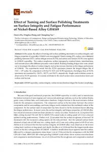
Fig. 3: Glass fibers placed in the prepared cavity Glass fibers were soaked in a silane coupling agent (Silane Bond Enhancer, pulpdent Corporation, USA) as shown in (Fig.4) for 5 minutes and allowed to air dry. Glass fibers (20 x 3 mm) were then placed in cavity prepared in the specimen and the entire space was filled with auto polymerizing acrylic resin. The samples were then cured in a pressure pot at a temperature of 37°C and pressure of 30 psi for 30 minutes. Samples with glass fiber were prepared with and without application of silane coupling agent. After being repaired the specimens were carefully restored to their original dimensions using sand paper and stored in 37°C distilled water for 48 hours before the test.
Fig.2: Heat cured acrylic specimens arranged in the lower have of the flask according to drown measured lines and the gap between the samples filled with wax. After dewaxing, separating medium was applied and the fractured surfaces were painted with monomer liquid and left for 3 minutes before mixing and packing. In case of repair using auto polymerizing resin, specimens were invested as above using conventional flasking procedure. After dewaxing, separating medium was applied. The interface surfaces of the prepared joints were wetted with the auto polymerizing monomer for 3 minutes. A small amount of the polymer was poured into the joint space then wetted with the monomer. This alternate procedure was continued until the joint had been built up to a slightly excess amount for polymerization shrinkage and finishing, as the repair material lost its surface glaze, the entire flask and contents were placed into a pressure pot at a temperature of 37°C and subjected to 30 psi pressure for 30 minutes. When glass fibers were used for repair, a cavity (1x5x30 mm) for transverse strength and (2x4x24 mm) for impact strength was prepared in the centre for each specimen. Specimens were repositioned in the similar fashion as mentioned above (Fig.3).
Fig.4: Glass fibers soaked in silane coupling agent
http://www.americanscience.org
117
[email protected]
Journal of American Science
2010;6(9)
Description of groups Groups 1
2
3
4.
5
6
Transverse Strength Heat Cure un repaired samples used as control for transverse strength. Samples repaired with Heat Cure having butt joint for transverse strength. Samples repaired with Heat Cure having 45 degree bevel joint for transverse strength. Samples repaired with Cold Cure having butt joint for transverse strength. Samples repaired with Cold Cure having 45 degree bevel joint for transverse strength. Samples repaired with Cold Cure and glass fibers having butt joint for transverse strength.
Code TC
THB
THF
TCB
TCF
TGB
7
Samples repaired with Cold Cure and glass fibers having 45 degree bevel joint for transverse strength.
TGF
8.
Samples repaired with Cold Cure and glass fibers treated with silane coupling agent having butt joint for transverse strength.
TGBS
9
Samples repaired with Cold Cure and glass fibers treated with silane coupling agent having 45 degree bevel joint for transverse strength.
TGFS
TOTAL NO. OF SAMPLES
54
Impact Strength Heat Cure un repaired samples used as control for Impact strength. Samples repaired with Heat Cure having butt joint for Impact strength. Samples repaired with Heat Cure having 45 degree bevel joint for Impact strength. Samples repaired with Cold Cure having butt joint for Impact strength. Samples repaired with Cold Cure having 45 degree bevel joint for Impact strength. Samples repaired with Cold Cure and glass fibers having butt joint for Impact strength. Samples repaired with Cold Cure and glass fibers having 45 degree bevel joint for Impact strength. Samples repaired with Cold Cure and glass fibers treated with silane coupling agent having butt joint for Impact strength. Samples repaired with Cold Cure and glass fibers treated with silane coupling agent having 45 degree bevel joint for Impact strength.
Code
n = no. of samples
IC
6
IHB
6
IHF
6
ICB
6
ICF
6
IGB
6
IGF
6
IGBS
6
IGFS
6
54
108
Evaluation of Transverse Test Instron Universal testing machine (Instron UTM, Model: 5569,U.K.) It has a load ranging from 2.5 N to 50 KN, with a digital data recording system. The software used was series 9 software or Merlin software. The cross head speed could range from 0.01mm/min to 500mm/min. The specimens were tested for transverse strength with a three point bending test using this Instron Universal testing machine at a cross head speed of 2mm / min and span length of 50mm. The load was applied to the centre of 2mm repaired area for the experimental groups and to the centre of control specimens until fracture occurred (Fig.5).
http://www.americanscience.org
The amount of deflection and the load at fracture were noted. The transverse strength was calculated using the following formula42. Transverse strength (S) = 3 PL / 2bd2 Where, P = Fracture load L = Span length b = Sample width d = sample thickness.
118
[email protected]
Journal of American Science
2010;6(9)
3. Results Evaluation of transverse strength: Table (I) Statistical comparison (t-test) of the mean Transverse strength (MPa) of samples of control group 1(TC), heat cure denture base material with samples repaired by different methods including heat cure, cold cure, cold cure with glass fiber with and without silane coupling agent treatment having butt and 450 bevel joint. Groups/Sample Mean ± SD P codes 56.32 1.382 Group 1 (TC) 0.0000* 1.332 Group 2 (THB) 33.47 Group 1 (TC) Group 3 (THF)
56.32 39.52
1.382 1.295
0.0000*
Fig.5: Test for transverse strength under progress using Instron Universal testing machine
Group 1 (TC) Group 4 (TCB)
56.32 26.34
1.382 0.6712
0.0000*
Evaluation of Impact Strength: For the impact testing the samples were tested using Izod Impact tester (CEAST,RESIL Impactor, Italy), resolution 0.001J, range is 0.5J to 25J, En 0.04J. The specimens were clamped at one end and a swinging pendulum of 0.5 joules was used to break the specimens (Fig.6). The absorbed energy by the specimen was noted. The impact strength was calculated using the formula42: Impact strength = E / b x d Where E - is the absorbed energy b - is the sample width d - is the sample thickness The obtained data was tabulated and statistically analyzed, using students paired t test.
Group 1 (TC) Group 5 (TCF)
56.32 31.37
1.382 2.088
0.0000*
Group 1 (TC) Group 6 (TGB)
56.32 38.03
1.382 1.594
0.0000*
56.32 1.382 Group 1 (TC) 2.364 Group 7 (TGF) 43.60 Group 1 (TC) 56.32 1.382 Group8 43.91 1.912 (TGBS) Group 1 (TC) 56.32 1.382 Group 9 45.96 2.162 (TGFS) *= Significant (p-value < 0.05); no. = each group
0.0000* 0.0000*
0.0000* 6 samples in
From table (I), It was observed that the mean transverse strength of the Group 1(TC), the control group was highest 56.32MPa, followed by Group 9(TGFS) 45.96MPa and Group 8(TGBS) 43.91MPa. Group 7(TGF) 43.60MPa ,Group 6(TGB) 38.03MPa and Group 3(THF) 39.52MPa, also showed considerable transverse strength, while the Group 2(THB) 33.47MPa and Group 5(TCF) 31.37MPa did not show a very high Transverse strength compared to Group 1(TC). Minimum value was observed of Group 4(TCB) 26.34MPa, while Maximum value is shown by Group 9(TGFS) 45.96MPa.
Fig.6: Test for Impact strength under progress using Ceast, Resil Impactor machine
http://www.americanscience.org
119
[email protected]
Journal of American Science
2010;6(9)
Table (II d) Statistical comparison (t-test) between the mean Transverse strength (MPa) of samples repaired by cold cure and the samples repaired by cold cure and glass fiber having both butt joint and 450bevel joint.
Table (II a) Statistical comparison (t-test) between the mean Transverse strength (MPa) of samples repaired by heat cure and the samples repaired by cold cure method having both butt joint and 45 ° bevel joint. Groups/Sample codes
Mean ± SD
P
Group 2 (THB) Group 4 (TCB) Group 3(THF) Group 4 (TCB) Group 2 (THB) Group 5 (TCF) Group 3(THF) Group 5 (TCF)
33.47 26.34 39.52 26.34 33.47 31.37
1.332 0.6712 1.295 0.6712 1.332 2.088
0.0649
39.52 31.37
1.298 2.088
0.0000*
0.0000* 0.0000*
*= Significant (p-value < 0.05); no. = 6 samples in each group Table (II b) Statistical comparison (t-test) between the mean Transverse strength (MPa) of samples repaired by heat cure and the samples repaired by cold cure and glass fiber method having both butt joint and 450bevel joint. Groups/Sample codes
Mean ± SD
Group 2 (THB) Group 6 (TGB) Group 3(THF) Group 6 (TGB) Group 2 (THB) Group 7 (TGF) Group 3(THF) Group 7 (TGF)
33.47 38.08 39.52 38.03 33.47 43.60
1.332 1.592 1.295 1.594 1.332 2.364
39.52 43.60
1.298 2.364
Mean ± SD
Group 2 (THB) Group8 (TGBS) Group 3 (THF) Group8 (TGBS) Group 2 (THB) Group9 (TGFS)
33.47 43.91 39.52 43.91 33.47 45.96
1.332 1.912 1.295 1.912 1.332 2.162
Group 4(TCB) Group6(TGB) Group 5(TCF) Group6(TGB) Group 4(TCB) Group7(TGF) Group5(TCF) Group7(TGF)
26.34 38.03 31.37 38.03 26.34 43.60
0.6712 1.594 2.088 1.594 0.6712 2.364
31.37 43.60
2.088 2.364
P 0.0000* 0.0001* 0.0000* 0.0000*
Table (II e) Statistical comparison (t-test) between the mean Transverse strength (MPa) of samples repaired by cold cure and the samples repaired by cold cure and glass fiber treated with silane coupling agent, having both butt joint and 450bevel joint.
P 0.0003* 0.1053 0.0000* 0.0041*
Groups/Sample codes
Mean ± SD
Group 4(TCB) Group8(TGBS) Group 5(TCF) Group8(TGBS) Group 4(TCB) Group9(TGFS) Group5(TCF) Group9(TGFS)
26.34 43.91 31.37 43.91 26.34 45.96
0.6712 1.912 2.088 1.912 0.6712 2.162
31.37 45.96
2.088 2.162
P 0.0000* 0.0000* 0.0000* 0.0000*
*= Significant (p-value < 0.05); no. = 6 samples in each group Table (III) Statistical comparison (t-test) between the mean Transverse strength (MPa) of samples having butt joint and 450bevel joint among the groups prepared by same method.
P 0.0000* 0.0009* 0.0000*
39.52 1.295 Group 3 (THF) 0.0001* 45.96 2.162 Group9 (TGFS) *= Significant (p-value < 0.05); no. = 6 samples in each group
http://www.americanscience.org
Mean ± SD
*= Significant (p-value < 0.05); no. = 6 samples in each group
*= Significant (p-value < 0.05); no. = 6 samples in each group Table (II c) Statistical comparison (t-test) between the mean Transverse strength (MPa) of samples repaired by heat cure and the samples repaired by cold cure and glass fiber treated with silane coupling agent, having both butt joint and 450bevel joint Groups/Sample codes
Groups/Sample codes
Groups/Sample codes
Mean ± SD
Group 2 (THB) Group 3(THF) Group 4 (TCB) Group 5 (TCF) Group 6 (TGB) Group 7(TGF)
33.47 39.52 26.34 31.37 38.03 43.60
1.332 1.295 0.6712 2.088 1.594 2.364
P 0.0000* 0.0002* 0.0007*
43.91 1.912 Group8 (TGBS) 0.1130 45.96 2.162 Group9 (TGFS) *= Significant (p-value < 0.05); no. = 6 samples in each group
120
[email protected]
Journal of American Science
2010;6(9)
From Tables ( IIa,b,c,d,e) and table (III), All the possible comparisons of the groups were done for samples tested for transverse strength using students paired t test. The comparisons showed advantage of the 45 degree bevel and fiber reinforcement, slightly higher strength was observed when the fibers were treated with silane coupling agent.
Table (V a) Statistical comparison (t-test) between the mean Impact strength (KJ/m2) of samples repaired by heat cure and samples repaired by cold cure method having butt joint and 450bevel joint. Groups/Sample Mean ± SD P codes 0.9033 0.01751 Group 2 (IHB) 0.0000* 0.4583 0.02858 Group 4(ICB) 0.960 0.07950 Group 3 (IHF) 0.0000* 0.4583 0.02858 Group 4 (ICB) 0.9033 0.01751 Group 2 (IHB) 0.0000* 0.5250 0.07583 Group 5(ICF)
Evaluation of Impact strength Table (IV) Statistical comparison (t-test) between the mean Impact strength (KJ/m2) of samples of control group (IC), heat cure denture base material with samples repaired by different methods including heat cure, cold cure, cold cure with glass fiber with and without silane coupling agent treatment having butt and 450 bevel joint. Groups/Sample Mean ± SD P codes 0.1089 1.592 Group 1 (IC) 0.0000* 0.9033 0.01751 Group 2 (IHB) 1.592 0.1089 Group 1 (IC) 0.0000* 0.960 0.07950 Group 3 (IHF) 0.1089 1.592 Group 1 (IC) 0.0000* 0.4583 0.02858 Group 4 (ICB) Group 1 (IC) Group 5 (ICF)
1.592 0.525
0.1089 0.07583
0.0000*
Group 1 (IC) Group 6 (IGB)
1.592 0.987
0.1089 0.1080
0.0000*
1.592 Group 1 (IC) 1.193 Group 7 (IGF) 1.592 Group 1 (IC) 1.150 Group 8 (IGBS) 1.592 Group 1 (IC) 1.613 Group 9 (IGFS) *= Significant (p-value < 0.05); each group
0.960 0.07950 Group3 (IHF) 0.0000* 0.5250 0.07583 Group5 (ICF) *= Significant (p-value < 0.05); no. = 6 samples in each group Table (V b) Statistical comparison (t-test) between the mean Impact strength (KJ/m2) of samples repaired by heat cure and samples repaired by cold cure and glass fiber having butt joint and 450bevel joint.
0.1089 0.0000* 0.1113 0.1089 0.0000* 0.2417 0.1089 0.8864 0.3455 no. = 6 samples in
Mean ± SD
Group 2 (IHB) Group 6(IGB) Group 3 (IHF) Group 6 (IGB) Group 2 (IHB) Group 7(IGF)
0.9033 0.987 0.960 0.987 0.9033 1.193
0.01751 0.1080 0.07950 0.1080 0.01751 0.1113
P 0.0917 0.6367 0.0001*
Group3 (IHF) 0.960 0.07950 0.0019* Group7 (IGF) 1.193 0.1113 *= Significant (p-value < 0.05); no. = 6 samples in each group Table (V c) Statistical comparison (t-test) between the mean Impact strength (KJ/m2) of Samples repaired by heat cure and samples repaired by cold cure and glass fiber treated with silane coupling agent having butt joint and 450bevel joint.
It was observed that the mean Impact strength of the Group 9(IGFS) 1.613 KJ/m2 was highest, followed by Group 1(IC) 1.592 KJ/m2, the control group and Group 7(IGF) 1.193 KJ/m2. Group 8(IGBS) 1.150 KJ/m2 also showed considerable transverse strength, followed by Group 6(IGB) 0.987 KJ/m2, Group 3(IHF)0.960 KJ/m2 and Group 2(IHB) 0.9033 Group KJ/m2. . Group 5(ICF) 0.5250 KJ/m2 showed very less Impact strength. Minimum value was observed of Group 4(ICB)0.4583 KJ/m2 , and Maximum value was shown by Group 9(IGFS) 1.613 KJ/m2.
http://www.americanscience.org
Groups/Sample codes
Groups/Sample codes
Mean ± SD
Group 2 (IHB) Group 8(IGBS) Group 3 (IHF) Group 8(IGBS) Group 2 (IHB) Group 9(IGFS)
0.9033 1.150 0.960 1.150 0.9033 1.613
0.01751 0.2417 0.07950 0.2417 0.01751 0.3455
P 0.0318* 0.0974 0.0005*
Group3 (IHF) 0.960 0.07950 0.0011* 0.3455 Group9(IGFS) 1.613 *= Significant (p-value < 0.05); no. = 6 samples in each group
121
[email protected]
Journal of American Science
2010;6(9)
From Tables (Va,b,c,d,e) and table (VI), All the possible comparisons of the groups were done for samples tested for Impact strength using students paired t test. The comparisons showed advantage of the 45 degree bevel and fiber reinforcement, slightly higher strength was observed when the fibers were treated with silane coupling agent.
Table (V d) Statistical comparison (t-test) between the mean Impact strength (KJ/m2) of Samples repaired by cold cure and samples repaired by cold cure and glass fiber having butt joint and 450bevel joint. Groups/Sample codes
Mean ± SD
P
Group 4 (ICB) Group 6 (IGB) Group 5 (ICF) Group 6 (IGB) Group 4 (IHB) Group 7 (IGF)
0.4583 0.987 0.5250 0.987 0.4583 1.193
0.0000*
0.02858 0.1080 0.07583 0.1080 0.02858 0.1113
4. Discussion Repair of a fractured denture base should not only match the original material in strength and color, but also easy to repair and quickly performed. According to (Rached R.N. 2004)(34) the choice of repair material depends upon the following factors; length of time required for making the repair, strength obtained with the repair material, and degree to which dimensional accuracy is maintained during the repair. With due consideration to above mentioned facts, this study was conducted to evaluate and compare the transverse strength and impact strength of acrylic resin test specimen which were repaired by auto polymerizing resin, heat cure resin and autopolymerizing resin and glass fibers (with and without treatment with silane coupling agent), with joint surface contour of butt and 45 degree bevel. DPI heat cure unrepaired resin was used as control group. One of the principal factors in the strength of a repair is the type of joint used in the repair. Harrison and Stansbury (1970)(38) studied the effect of three types of repair surface designs on the transverse strength of repaired acrylic resin. They found the rounded design surface to be superior to the rabbet and butt designs. Ward J.E. et al (1992)(39)also investigated the effect of different type of repair surface designs and concluded that round and 45degree bevel joints were statistically similar. Since it is easier clinically to prepare and finish a beveled joint, and a butt joint than other types of joints, these most commonly used repair surface designs were used in this study.
0.0000* 0.0000*
Group 5 (ICF) 0.5250 0.07583 0.0000* Group 7 (IGF) 1.193 0.1113 *= Significant (p-value < 0.05); no. = 6 samples in each group Table (V e) Statistical comparison (t-test) between the mean Impact strength (KJ/m2) of Samples repaired by cold cure and samples repaired by cold cure and glass fiber treated with silane coupling agent having butt joint and 450bevel joint. Groups/Sample codes
Mean ± SD
Group 4 (ICB) Group 8 (IGBS) Group 5 (ICF) Group 8 (IGBS) Group 4 (ICB) Group 9 (IGFS)
0.4583 1.150 0.5250 1.150 0.4583 1.613
0.02858 0.2417 0.07583 0.2417 0.02858 0.3455
P 0.0000* 0.0001* 0.0000*
Group 5 (ICF) 0.5250 0.07583 0.0000* Group 9 (IGFS) 1.613 0.3455 *= Significant (p-value < 0.05); no. = 6 samples in each group Table (VI) Statistical comparison (t-test) between the mean Impact strength (KJ/m2) of Samples having butt joint and 450bevel joint among the groups prepared by same method. Groups/Sample codes
Mean ± SD
Group 2 (IHB) Group 3 (IHF) Group 4 (ICB) Group 5 (ICF) Group 6 (IGB) Group 7(IGF)
0.9033 0.960 0.4583 0.5250 0.983 1.193
0.01751 0.07950 0.02858 0.07583 0.1080 0.1113
Transverse strength The findings from the table no. I shows that the highest transverse strength after repair was obtained by Group 9(TGFS) (cold cure with glass fibers treated with silane coupling agent having 450 bevel joint design) followed by Group 8(TGBS) (cold cure with glass fibers treated with silane coupling agent having butt joint design), Group 7(TGF) (cold cure with glass fibers having 450 bevel joint design), Group 3(THF) (Heat cure having 450 bevel joint design), Group 6(TGB) (cold cure with glass fibers having butt joint design), Group 2(THB) (Heat cure having butt joint design) and Group 5(TCF) (cold cure having 450 bevel joint design). The minimum value was observed of the Group 4(TCB) 26.34 MPa
P 0.1190 0.0716 0.0085*
Group8 (IGBS) 1.150 0.2417 0.0226* Group9 (IGFS) 1.613 0.3455 *= Significant (p-value < 0.05); no. = 6 samples in each group
http://www.americanscience.org
122
[email protected]
Journal of American Science
2010;6(9)
(cold cure with butt joint), the low transverse strength of the group as it was not reinforced with glass fiber and had a butt joint design; while in Group 5(TCF) 31.37MPa (cold cure having 450 bevel joint design) the increase in strength may be due to the effect of 450 bevel joint design as the geometry of 45-degree bevel increases the interfacial bond area and shifts the interfacial stress pattern more towards a shear stress and away from the more damaging tensile stress during repair (Ward et al.1992)(39). The mean transverse strength for control Group 1(TC) was found to be highest 56.32 MPa. The mean transverse strength in all the tested groups was significantly lower after repair. This is in accordance with the finding of Stipho (1998)(41,42) who conducted a study to repair the acrylic resin dentures base with glass fibers. There was 25% increase in transverse strength after reinforcement with glass fibers in Group9(TGFS) in comparison to the non-reinforced samples Group5(TCF). Aydin C. (2002)(44) also found 27.2% increase in transverse strength of auto polymerizing resin after reinforcing it with glass fibers. Group9(TGFS), Group8(TGBS), Group7(TGF) and Group6(TGB), all reinforced with glass fiber showed significantly higher transverse strength than other non-reinforced Groups, while only Group 3(THF) (Heat cure having 450 bevel design) showed higher transverse strength than Group6 (TGB), possibly due to combined effect of 450 bevel design and repaired with heat cure denture base material. Keyf F. et al (2000)(43) found that the transverse strength of the repaired samples with glass fibers was 80% of the control. The results of the present study are in close agreement to the findings of the above study. Fiber-reinforced polymers are successful in their application primarily because of their high specific modulus and specific strength. Because the modulus of elasticity of glass fibers is very high, most of the stresses are received by them without deformation. This may be the reason that glass reinforced specimens exhibited better flexural strength than the other specimen groups in this study.
than in the area of inner glass fiber. Finally, a fracture of glass fiber leads the test specimen to a complete fracture (Kaine et al 2000)(35). In this study, it was observed that glass fiber significantly increased the impact strength when compared with un reinforced self-cure specimens. 5. Conclusion Fractured specimen repaired by heat cure method showed 30-40% higher values of transverse strength as compared to cold cure Groups. The transverse and impact strength values after repair were highest with auto polymerizing resin with glass fibers after treatment with silane coupling agent, having 450 bevel joint. Samples repaired having Joint surface contour of 450 bevel, showed higher transverse strength. Impact strength was not affected in case of samples repaired by self cure and heat cure, but the strength increased in fiber reinforced Groups with and without silane coupling agent treatment. Testing samples and evaluation of the transverse and impact strength for this study were done in Shri Ram Institute for Industrial Research, Whitefield Bangalore and 3M India limited, Electronic city Bangalore. Corresponding author Emiel A. M. Hanna 1 Prosthodontic Department, 6 October University, Cairo, Egypt.
[email protected] 6. References 1. 1 Hargraves A. The prevalence of fractured dentures Brit Dent J 1969; 20:451-8. 2. Jagger DC, Harrison A, Jandt KD. The reinforcement of dentures. J. Oral Rehab1999; 26 : 185-194. 3. Chong KH, Chai J. Strength and mode of failure of unidirectional and bidirectional glass fiber-reinforced composite materials. Int J Prosthodont 2003; 16:161-6. 4. Solnit GS. The effect of methyl methacrylate reinforcement with silane-treated and untreated glass fibers. J Prosthet Dent 1991; 66:310-4. 5. Schreiber CK. Polymethylmethacrylate reinforced with carbon fibres. Br Dent J 1971;130:29-30. 6. Yazdanie N, Mahood M. Carbon fiber acrylic resin composite: an investigation of transverse strength. J Prosthet Dent 1985; 54:543-7.
Impact strength The highest impact strength was found to be of Group 9(IGFS) (repaired with cold cure and glass fiber treated with silane coupling agent having 450bevel joint) 1.613 KJ/m2 .Vallittu P.K. et al (1997)(40) found significant increase in impact strength after glass fiber reinforcement. Similar results were obtained by Kanie et al (2000)(35) .Glass fibers prevent the spread of delamination in the specimen. This means that the lengthening of polymer matrix caused by flexural test, stops at the glass fiber. When polymer matrix is laminated with glass fiber, more delamination is seen in the area of outer glass fiber
http://www.americanscience.org
123
[email protected]
Journal of American Science
7.
8.
9.
10.
11.
12.
13.
14.
15.
16.
17.
18.
2010;6(9)
Gutteridge DL. The effect of including ultrahigh modulus polyetylene fiber on the impact strength of acrylic resin. Br Dent J 1988; 164:177-80. De Boer J, Vermilyea SG, Brady RE. The effect of carbon fiber orientation on the fatigue resistance and bending properties of two denture resins. J Prosthet Dent 1984; 51:119-21. Ekstrand K, Ruyter IE, Wellendorf H. Carbon/ graphite reinforced poly (methyl methacrylate): properties under dry and wet conditions. J Biomed Mater Res 1987; 21:1065-80. Vallittu PK. Comparison of the in vitro fatigue resistance of na acrylic resin removable partial denture reinforced with continuous glass fibers or metal wires. J Prosthodont 1996; 5:115-21. Vallittu PK. Glass fiber reinforcement in repaired acrylic resin removable dentures: preliminary results of a clinical study. Quintessence Int 1997; 28:39-44. Freilich MA, Duncan JP, Meiers JC, Goldberg AJ. Preimpregnated, fiberreinforced prostheses. Part I. Basic rationale and complete-coverage and intracoronal fixed partial denture designs. Quintessence Int 1998; 29:689-96. Saygili G, Sahmali SM, Demirel F. The Effect of placement of glass fibers and aramid fibers on the fracture resistance of provisional restorative materials. Operat Dent 2003; 28:80-5. Vallittu PK. Compositional and weave pattern analyses of glass fibers in dental polymer fiber composites. J Prosthodont 1998; 7:170-6. Mullarky RH. Aramid fiber reinforcement of acrylic appliances. J Clin Orthod 1985; 19:655-8. Hull D, Shi YB. Damage mechanism caracterization in composite damage tolerance investigation. Comp Struct 1993; 23:99-120. Gutteridge DL. Reinforcement of poly(methyl methacrylate) with ultra-highmodulus polyethylene fibre. J Dent 1992; 20:50-4. Ledizesky NH, Ho CF, Chow TW. Reinforcement of complete denture bases with continuous high performance polyethylene fibers. J Prosthet Dent 1992; 68:934-9.
http://www.americanscience.org
19. Dixon DL, Breeding LC. The transverse strength of three denture base resins reinforced with polyethylene fibers. J Prosthet Dent 1992; 67:417-9. 20. Ledizesky NH, Chow TW, Ward IM. The effect of highly drawn polyethylene fibres on the mechanical properties of denture base resins. Clin Mater 1990; 6:209-25. 21. Ledizesky NH, Cheng YY, Chow TW, Ward IM. Acrylic resin reinforced with chopped high performance polyethylene fiber – properties and denture construction. Dent Mater 1993; 9:128-35. 22. Cheng YY, Hui OL, Ledizesky NH. Processing shrinkage of heat-curing acrylic resin reinforced with high-performance polyethylene fibers. Biomater 1993; 14:77580. 23. Dixson DL, Ekstrand KG, Breeding LC. The transverse strength of three different denture base resins. J Prosthet Dent 1991; 66:510-3. 24. Vallittu PK. Ultra-high-modulus polyethylene ribbon as reinforcement for denture polymethyl methacrylate. A short communication. Dent Mater 1997;13:381-2. 25. Ramos V, Runyan DA, Christensen LC. The effect of plasma-treated polyethylene fiber on the fracture strength of polymethyl methacrylate. J Prosthet Dent 1996; 76:94-6. 26. Altieri JV, Burstone CJ, Goldberg AJ, Petel AP. Longitudinal clinical evaluation of fiberreinforced composite fixed partial dentures: A pilot study. J Prosthet Dent 1994; 71:1622. 27. Freilich MA, Karamarker AC, Bustone CJ, GOoldberg AJ. Development and clinical applications of light-polymerized fiberreinforced composite. J Prosthet Dent 1998; 80:311-8. 28. Rosen MR. From treating solution to filler surface and beyond. The life history of a silane coupling agent. J Coat Technol 1978; 50:70-82. 29. Ellakwa AE, Shortall AC, Marquis PM. Influence of fiber type and wetting agent on the flexural properties of an indirest fiber reinforced composite. J Prosthet Dent 2002; 88:485-90. 30. Soederholm JJ, Shang SW. Molecular orientation of silane at the surface of colloidal silica. J Dent Res 1993; 72:1050-4. 31. Finn SR, Springer GS. Delaminations in composite plates under transferse static or impact loads – A model. Comp Struct 1993; 23:177-90.
124
[email protected]
Journal of American Science
2010;6(9)
32. Andreopoulos AG, Polyzois GL. Repair of denture base resins using visible light-cured materials. J. Prosthet Dent 1994; 72 : 462468. 33. Rached NR, Powers JM, Antoninha A and Cury DB. Repair strength of autopolymerizing, microwave and conventional heat-polymerized acrylic resins. J. Prosthet Dent 2004; 92 : 79-82. 34. Kanie T, Fuji K, Arikawa H, Inoue K. Flexural properties and impact strength of denture base polymer reinforced with woven glass fibers. Dent Mater 2000; 16: 150-158. 35. Vallittu PK. Glass fiber reinforcement in repaired acrylic resin removable dentures: Preliminary results of a clinical study. Quintessence Int 1997; 28 : 39-44. 36. Councils on Dental Materials and Devices. Revised American Dental Association specification No. 12 for denture base polymers. J. Am. Dent. Assoc 1975; 90 : 451-58. 37. Harrison WM and Stansburry BE. The effect of joint surface contours on the transverse strength of repaired acrylic resin. J. Prosthet Dent 1970; 23: 464-472.
38. Ward JE, Moon PC, Levine RA, Behrendt CL. Effect of repair surface design, repair material and processing method on the transverse strength of repaired acrylic denture resin. J. Prosthet Dent 1992; 67: 815-20. 39. Vallittu PK. Curing of silane coupling agent and its effect on transverse strength of autopolymerizing polymethyl methacrylate – glass fiber composite. J. Oral Rehab 1997; 24 : 124-130. 40. Stipho HD. Repair of acrylic resin denture base reinforced with glass fiber. J. Prosthet Dent 1998; 80: 546-550. 41. Stipho HD. Effect of glass fiber reinforcement on some mechanical properties of autopolymerizing polymethyl methacrylate. J. Prosthet Dent 1998; 79: 580-4. 42. Keyf F, Uzun G. The effect of glass fibrereinforcement on the transverse strength, deflection and modulus of elasticity of repaired acrylic resin. Int. Dent. J 2000; 50 : 93-97. 43. Aydin C, Yilmaz H and Caglar A. Effect of glass fiber reinforcement on the flexural strength of different denture base resins. Quintessence Int 2002; 33: 457-463.
5/5/2010
http://www.americanscience.org
125
[email protected]