Keywords: Asymmetric gear, Involute Curve, Pressure Angle. I: INTRODUCTION. Gears are used .... The top land thickness coefficient is where inv x = tan x - x is ...
IOSR Journal of Engineering Apr. 2012, Vol. 2(4) pp: 616-620
Effect of Pressure Angle on Bending Stress and Deformation of Asymmetric Spur Gear Using FEA 1
MR. K. D. DADHANIYA, 2PROF. K. P. HIRPAR, 3MR. K. M. VYAS
1
M.E.[Machine Design] Student, Department Of Mechanical Engineering, R. K. College Of Engineering And Technology, Rajkot, Gujarat 2 Asst. Professor, Department Of Mechanical Engineering, R. K. College Of Engineering And Technology, Rajkot, Gujarat 3 M.E.[Machine Design] Student, Department Of Mechanical Engineering, R. K. College Of Engineering And Technology, Rajkot, Gujarat
ABSTRACT: A gear is a rotating machine part having cut teeth, which mesh with another toothed part in order to transmit torque. Gears may be spur, helical, bevel or worm in which spur gear is most common type of gear used in engineering applications. In the automobile and aerospace industries, higher strength, higher reliability and lighter weight gears are necessary as lighter automotives continue to be in demand. This has lead to development of new designs, such as gears with asymmetric teeth. The geometry of these teeth is such that the drive side profile is not symmetric to the coast side profile and it is beneficial for special applications where the loading of the gear is uni-directional. In such an instance, the loading on the gear tooth is not symmetric, thus calling for asymmetric teeth. The coefficient of asymmetry is dependent on pressure angle; therefore study of effect on pressure angle on asymmetric tooth is of great importance. This paper presents a study on effect of pressure angle on asymmetric involute spur gear.
Keywords: Asymmetric gear, Involute Curve, Pressure Angle. I: INTRODUCTION Gears are used for transmitting power from sources to applications. Gears are used widely in many applications ranging from small watches to automotive transmission and aerospace engines. Toothed gears are used to change the speed and power ratio as well as direction between input and output. The spur gears are the simplest and most common type of gears used in industries. They consist of a cylinder or disk with the teeth projecting radially and meshed together correctly only if they are fitted to parallel shaft. A symmetric involute tooth is formed by two involutes of same base circles, outer circle diameter and fillet. The tooth form has left–right symmetry in the involute cylindrical gear and the same performance can be obtained at forward and backward rotation. An asymmetric involute tooth is formed by two involutes of different base circles, outer circle diameter and fillet as shown in figure 1. It is common fact that the two profiles or sides of a gear tooth in almost all the gear drive are functionally different. A significantly higher workload for a longer period of time is applied to one profile than the opposite one. This functional difference is well reflected in the design of the tooth shape of an Asymmetric Gear.
Fig.1 Asymmetric tooth The effects of increasing pressure angle are summarized as below: The limiting number of teeth to avoid undercutting is lowered. The shape of the tooth becomes more pointed or peaked. Tooth flank become more curved. The relative sliding velocity is reduced. The contact ratio and overlap are reduced. The tooth pressure and axial pressure increase. Tooth load carrying capacity increases [17].
II: LITERATURE STUDIED A method for design of gears with asymmetric teeth is presented. Synthesis of asymmetric spur gears with subsequent determination of generating rack parameters is also described. It is found that asymmetric tooth geometry (with larger pressure angle on drive tooth side) allow for an ISSN: 2250-3021
www.iosrjen.org
616 | P a g e
IOSR Journal of Engineering Apr. 2012, Vol. 2(4) pp: 616-620 increase in load capacity while reducing weight and dimensions for same types of gears [1]. Maximum bending and contact ratio depending on number of tooth and pressure angle of the drive side, for asymmetric drives is estimated, tooth form and stress concentration factors for different parameter is also determined. The determination of the tooth form and stress concentration factors for asymmetric tooth has been accomplished for each different parameter (pressure angles, tool radius, rack shift, etc.) [2]. Direct gear design method for spur and helical involute gear is developed which allows analysis of a wide range of parameters for all possible gear combinations to find out the most suitable solution for a particular application [3]. An area of existence of gear is constructed which allows the location of gear pairs with certain characteristics [4]. The Lewis factor for different coefficient of asymmetry is calculated for different number of teeth and it is found that Lewis factor increases with coefficient of asymmetry and number of teeth [5]. Influence on the maximum values of stress and displacement of the asymmetric teeth in meshing, in relation with the coefficient of asymmetry is analysed using FEA. It is found that if the aim of designing is to reduce the contact stress, direct asymmetric gear with bigger coefficient of asymmetry is advantageous. [6]. Fillet profile optimization techniques based on FEA and a random search method are presented for gears with symmetric and asymmetric teeth. The study shows reduced bending stress in comparison with traditionally designed gears. The bending stress reduction provided by the fillet optimization can be converted into other gear performance benefits, such as contact stress reduction and increased gear mesh efficiency [7]. Effect of pressure angel on contact ratio and tooth peaking is studied. It has been found that as drive/coast side pressure angle increases the contact ratio and tooth peaking decreases, which means maximum pressure angle is constraint by the safe contact ratio and tooth peaking effect. [8]. Effect of bending stress at the critical section for different pressure angle on the drive side along with the profile shift is studied. Due to positive profile shift, the thickness of tooth at the root is increases, resulting in greater load carrying capacity of the teeth. Profile shift varied from 0 to 0.5 and found lowest bending strength at critical section with profile shift value of 0.5; drive side pressure angle is also varied from 20 to 30 degree and found lowest bending strength at critical section with 30 degree pressure angle. It has been found that implementation of positive profile shift and pressure angle modification reduces bending stress considerably [9]. Reduction in bending stress value found for circular root fillet design in comparison to that of bending stress value in trochoidal root fillet design [10]. Dynamic behaviour of spur gears with asymmetric tooth design is analysed. The static transmission error, at the centre of the single tooth contact zone, decreases with increasing of pressure angle on drive side. The result implies that the usage of long addendum for involute spur gears with asymmetric teeth may be an alternative way to reduce the dynamic response as well decreasing tooth stress at root [11]. ISSN: 2250-3021
Critical section thickness of asymmetric gear is estimated using C programming. It has been found that critical section thickness increases with increasing pressure angle on drive side for certain limit [12]. Single-tooth bending fatigue strength and scuffing resistance of asymmetric and symmetric tooth gear determined experimentally by designing, fabricating and testing specimens. Test results demonstrated higher bending fatigue strength for both the asymmetric tooth form and optimized fillet form compared to symmetric designs. Scuffing resistance was significantly increased for the asymmetric tooth form compared to a conventional symmetric involute tooth design [13]. Asymmetric plastic gear is manufactured on CNC machine tool with end mill cutter and radial run-out, longitudinal and profile form errors are also measured and found that achieved properties of surface, flank forms and run-outs are sufficient for specific applications like agriculture machines [14]. An example of implementation of the gears with asymmetric tooth profile is two stage planetary gearbox of the TV7-117S turboprop engine is demonstrated. This engine has been used in the Russian airplane IL-114 for several years and is going to be used in IL-112, MIG-110, TU-136 airplanes which resulted in extremely low weight to output torque ratio [15].
III: NOMENCLATURE a b C c
Generating rack tooth addendum, mm (mm) Generating rack tooth dedendum, mm (mm) Centre distance, mm (mm) Radial clearance, mm (mm) Tooth thickness coefficient Base circle diameter, mm (mm) Tip circle diameter, mm (mm) Outside circle diameter, mm (mm) Pitch diameter, mm (mm) Generating pitch diameter, mm (mm)
k
Root diameter, mm (mm) Coefficient of asymmetry Gear ratio Top land thickness coefficient Contact ratio Top land thickness, mm (mm) Tooth thickness on pitch diameter, mm (mm) Generating rack tooth thickness, mm (mm) Pressure angle, deg Profile angle in the bottom contact point, deg
Profile angle on outside circle Generating rack profile angle, deg. v Profile angle in the intersection (tip) point of the two involutes, deg Subscript c Coast involute profile d Drive involute profile 1 Pinion 2 Gear
www.iosrjen.org
617 | P a g e
IOSR Journal of Engineering Apr. 2012, Vol. 2(4) pp: 616-620
IV: DESIGN EQUATIONS OF ASYMMETRIC SPUR GEAR An asymmetric involute tooth is formed by two involutes of different base circles Dbd and Dbc, outside circle diameter Do and fillet. The profile angles in the intersection point of the two involutes (tip angles) are
Tooth thickness at the pitch circle diameter of the pinion and gear are
The coefficient of asymmetry is
V: GENERATION OF INVOLUTE TOOTH PROFILE USING MATLAB
20 degree involute spure profile
The top land thickness coefficient is 4
where inv x = tan x - x is involute function of the angle x. The coefficient mo is selected within (0.25-0.4)/N range, where N is number of teeth. The pressure angles can be found from
y [mm]
3 2 1 0 -1
The contact ratios are for drive sides:
For coast sides:
0
1
2 x [mm]
3
4
To avoid the interference, the profile angles in the bottom points of the coast sides (they are more sensitive) must be larger or equal to zero:
For the pinion:
For gear
The profile angles in the bottom points of the drive sides are
ISSN: 2250-3021
www.iosrjen.org
618 | P a g e
IOSR Journal of Engineering Apr. 2012, Vol. 2(4) pp: 616-620 25 degree involute spure profile
VI: BENDING STRESS ANALYSIS USING FEA A solid 3D model with parameters shown in table 1and different pressure angle on drive side (20, 25, 30, 35) generated using ANSYS WORKBENCH 11. Power, watt 25000
5
y [mm]
4 3
Speed, rpm
1440
2
Module, mm
5
1
No of teeth
28
0
Face width, mm 50 Table 1 Gear parameters
0
2 x [mm]
4
Static structural analysis of ANSYS WORKBENCH 11 is used for analysis of gear tooth. Material properties used for analysis: Modulus of elasticity = 200 GPa and Poisson’s ratio = 0.3 Models of gear are imported to the simulator of ANSYS WORKBENCH 11. Material properties as shown above is assign to the gear tooth model. Mesh is generated in imported model. Then generated mesh is refined at root as shown in figure 3 to get more accurate results.
30 degree involute spure profile 6
y [mm]
5 4 3 2 1 0 -2
0
2 4 6 x [mm] 35 degree involute spure profile
8
y [mm]
6 4 2
Fig.3 Refinement of meshing Meshed gear is loaded and boundary condition is applied. Then, above defined problem is solved. Figure 4 shows the von-Mises stress distribution.
0 -2
0
2 x [mm]
4
6
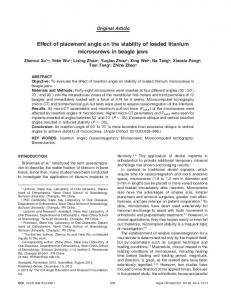
Fig.2 Involute profiles with different pressure angle The profiles shown in figure 2 are generated using MATLAB software. The different profiles are generated with 20, 25, 30 and 35 values of pressure angle. It can be concluded from figure 2 that as the value of pressure angle increases the profile becomes more curved; as a result it will increase the base of the gear tooth and reduce the value of tip thickness at addendum circle of the gear tooth. The increased base increases the bending strength but at the same time reduction in tip thickness decreases the tip strength.
Fig.4 stress distribution in gear tooth ISSN: 2250-3021
www.iosrjen.org
619 | P a g e
IOSR Journal of Engineering Apr. 2012, Vol. 2(4) pp: 616-620 All modelled gear are analysed for stress and deformation by above mentioned procedure. Different values of stress and deformation for each model is shown in table 2 Gear model (drive/coast) 20/20 25/20 30/20 35/20
von mises, N/mm2 47.06 44.21 41.03 37.98
Total deformation, mm 0.0038312 0.0035160 0.0033565 0.0031818
Table 2 Bending stresses and deformation
VII: CONCLUSION It can be concluded from table 3 that asymmetric teeth with higher pressure angle on drive side have better performance than symmetric teeth with common pressure angle 20 degree for bending stress minimization. Bending stress is increased by 24% with 35 degree pressure angle on drive side than symmetric gear with 20 degree pressure angle. Deformation is reduced by 20% with 35 degree pressure angle on drive side than symmetric gear with 20 degree pressure angle. As the pressure angle on drive side increases, the bending stress decreases and bending load capacity increases. Decision on maximum magnitude of drive side/coast side pressure angle is constraint by the safe contact ratio and tooth peaking effect.
VIII: REFERENCES [1]
[2]
[3]
[4]
[5]
[6]
[7]
Alexander Kapelevich, “Geometry and design of involute spur gears with asymmetric teeth”, Elsevier Science Ltd., 1998. Kadir Cavdar, Fatih Karpat and Fatih C. Babalik, “Computer Aided Analysis of Bending Strength of Involute Spur Gears with Asymmetric Profile”, Journal of Mechanical Design, 2005. Alex Kapelevich and Roderick E. Kleiss, “Direct Gear Design For Spur And Helical Involute Gears”, Gear Technology, 2002. Alexander L. Kapelevich and Dr. Yuriy Shekhtman, “Area of Existence of Involute Gears”, Gear Technology, 2010. J.L. Moya, A.S. Machado, J.A. Velasquez, R. Goytisolo, A.E. Hernández, J.E. Fernández, and J.M. Sierra, “A Study in Asymmetric Plastic Spur Gears”, Gear solutions, 2010. Flavia CHIRA, Anamaria DASCALESCU, Vasile TISAN, Dinu STOICOVICI, “The study of the stress and displacements at the direct asymmetric gears in relation with the coefficient of asymmetry using the finite elements method”, Fascicle of Management and Technology Engineering, 2008. Alexander L. Kapelevich and Dr. Yuriy Shekhtman, “Tooth Fillet Profile optimization for Gears with Symmetric and Asymmetric Teeth”, Gear Technology, 2009.
ISSN: 2250-3021
Vedang Singh and S. Senthilvelan, “Computer Aided Design of Asymmetric Gear”, 13th National Conference on Mechanisms and Machines, 2007. [9] G. Mallesh, Dr. V B Math, Ashwij, Prabodh Sai Dutt R, Rajendra Shanbhag, “Effect of Tooth Profile Modification In Asymmetric Spur Gear Tooth Bending Stress By Finite Element Analysis”, 13th National Conference on Mechanisms and Machines, 2009. [10] Shanmugasundaram Sankar, Maasanamuthu Sundar Raj, Muthusamy Nataraj, “Profile Modification for Increasing the Tooth Strength in Spur Gear Using CAD”, http://www.SciRP.org/journal/eng, 2010. [11] Fatih Karpat, Stephen Ekwaro-Osire and Esn Karpat, “A Virtual Tool for Computer Aided Analysis of Spur Gears with symmetric Teeth”. [12] G. Mallesh, Dr. V B Math, Gajanan, Uttesh, Sridhar, “Estimation of Critical Section and Bending Stress Analysis for Asymmetric Spur Gear Tooth”, 14th National Conference on Mechanisms and Machines, 2009. [13] F.W. Brown, S.R. Davidson, D.B. Hanes and D.J. Weires, The Boeing Company, and A. Kapelevich, “Analysis and Testing of Gears with Asymmetric Involute Tooth Form and Optimized Fillet Form for Potential Application in Helicopter Main Drives”, 2010. [14] RAVAI NAGY Sandor, LOBONŢIU Mircea, “Manufacture of gears with asymmetric teeth on CNC machine tools”, Fascicle of Management and Technology Engineering, 2010. [15] Alexander L. Kapelevich, “Direct design of asymmetric gears: approach and application”, JSME International Conference on Motion and Power Transmissions, Matsushima Isles Resort, Japan, 2009. [16] Faydor L Litvin, “Gear geometry and applied theory” (second edition). [17] Gitin M Maitra, “Handbook of Gear Design” (second edition). [18] Joseph E Shigley, “Mechanical engineering design” (eighth edition). [8]
www.iosrjen.org
620 | P a g e