UDK 621.791/.792:669.71:669.3 Original scientific article/Izvirni znanstveni ~lanek
ISSN 1580-2949 MTAEC9, 50(1)89(2016)
V. D. MILA[INOVI] et al.: EFFECTS OF FRICTION-WELDING PARAMETERS ON THE MORPHOLOGICAL PROPERTIES ... 89–94
EFFECTS OF FRICTION-WELDING PARAMETERS ON THE MORPHOLOGICAL PROPERTIES OF AN Al/Cu BIMETALLIC JOINT VPLIV PARAMETROV TORNEGA VARJENJA NA MORFOLO[KE LASTNOSTI Al/Cu BIMETALNEGA SPOJA Veljko D. Mila{inovi}1, Radovan V. Radovanovi}2, Mijat D. Mila{inovi}1, Bojan R. Gligorijevi}3 1University of Belgrade, Faculty of Mechanical Engineering, Kraljice Marije 16, 11120 Belgrade, 2Academy of Criminalistic and Police Studies, Cara Du{ana 196, 11080 Belgrade, Serbia 3University
Serbia
of Belgrade, Innovation Center of Faculty of Technology and Metallurgy, Karnegijeva 4, 11120 Belgrade, Serbia
[email protected] Prejem rokopisa – received: 2014-12-14; sprejem za objavo – accepted for publication: 2015-01-20 doi:10.17222/mit.2014.304
The objective of this research is to consider the effects of certain parameters of the friction-welding process on the morphology of an aluminum/copper joint. The effect of the following parameters was monitored: the operating time, the operating pressure, the forging time and the forging pressure. The speed was constant during the binding process and reached 1500 min–1. The preparation of the welding materials was performed in accordance with the industrial production conditions. With the SEM-EDS analysis, it was found that the morphology of the Al/Cu interface slightly changes when we change the distance from the rotation axis, irrespective of the combination of the friction-welding parameters. Apart from this, the joined effects of the operating pressure of 48 MPa and the forging pressure of 160 MPa caused a morphological change of the Al/Cu interface, while the forging time at the moment of the combined pressurizing effect significantly influenced the modification of the Al/Cu interface shape within a very narrow time interval of only a few seconds. Keywords: friction welding, bimetallic joint, interface, aluminum, copper, SEM-EDS Cilj te raziskave je obravnava vpliva nekaterih parametrov procesa tornega varjenja na morfologijo spoja aluminij/baker. Pregledan je bil vpliv naslednjih parametrov: ~as delovanja, tlak pri obratovanju, ~as kovanja in tlak pri kovanju. Hitrost 1500 min–1 je bila med spajanjem konstantna. Priprava materialov za varjenje je bila izvr{ena skladno s pogoji industrijske proizvodnje. S pomo~jo SEM-EDS analiz je bilo ugotovljeno, da se morfologija spoja Al/Cu rahlo spreminja s spreminjanjem razdalje od rotirajo~e osi, ne glede na kombinacijo parametrov procesa tornega varjenja. Poleg tega je skupni u~inek delovnega tlaka 48 MPa in tlaka pri kovanju 160 MPa povzro~il morfolo{ke spremembe spoja Al/Cu, medtem ko ~as kovanja, v trenutku kombiniranega stiskanja mo~no vpliva na spremembo oblike Al/Cu spoja v zelo ozkem temperaturnem intervalu samo nekaj sekund. Klju~ne besede: torno varjenje, bimetalni spoj, stik, aluminij, baker, SEM-EDS
1 INTRODUCTION In energetics, bonding elements, originally used for bonding copper and aluminum cables, were made of copper (Figures 1a to 1c) and a joint between aluminum (Al) and copper (Cu) (Al/Cu joint) was most frequently made by creating a mechanical contact between the two metals, e.i., by crimping them (Figure 1a).1 The bonding of Al cables onto the Cu busbars in electrical substations was conducted using Cu lugs where the connection between an Al cable and a Cu lug was made by crimping (Figure 1b)2 or by tightening a screw (Figure 1c)3 of the inserted Al cable. As a result of the high copper price, new and more cost-effective solutions were found, such as Al lugs with an inserted Cu ring (Figure 1d).4 However, the use of such Al/Cu joints proved to be unreliable in the long run. The reasons for this were the following: 1) the weakening of the joint during its use at higher temperatures (due to different linear Al and Cu expansion coefficients) and 2) a large transient electrical resisMateriali in tehnologije / Materials and technology 50 (2016) 1, 89–94
tance at the interface, which is one of the deficiencies of a joint based on the mechanical type of connection. Further research, with the objective to find ways for achieving a tighter bond between Al and Cu, led to the discovery of Al/Cu bonding elements where the connection between Al and Cu is achieved with an interdiffusion of the solid-state atoms. The procedure, with which such a connection is formed, is called friction welding.
Figure 1: Cu bonding elements: a) Cu butt connector, b) Cu crimping lug, c) Cu lug with a screw, d) Al lug with the inserted Cu ring1–4 Slika 1: Cu priklju~ni elementi: a) Cu valjasti priklju~ek, b) Cu priklju~ek z zanko, c) Cu priklju~ek z vijakom, d) Al priklju~ek z vlo`enim Cu obro~kom1–4
89
V. D. MILA[INOVI] et al.: EFFECTS OF FRICTION-WELDING PARAMETERS ON THE MORPHOLOGICAL PROPERTIES ...
Friction welding represents a process of bonding similar or dissimilar materials that occurs at the temperatures below the melting temperature of the base material that is the easiest to melt and are high enough to allow the optimum interdiffusion distance between the atoms of the metals, with the aim of achieving the required tensile strength.5 In practice, there are two methods of friction welding, different only in the method of the energy supply required for the process of welding/bonding metals. These are the continuous and inertia friction welding. In terms of continuous friction welding, the energy required for welding is supplied from a steady power source all the way to the forging phase, while the energy required for inertia friction welding is obtained from accumulated flywheel energy.6–8 In addition to the parameters of the welding process (time, pressure and speed), a significant impact on the quality of the achieved connection between Al and Cu is also made by the contact surfaces.9,10 The preparation of the bonding surfaces is of special importance since each type of surface impurities may disturb the required quality level of the joint.11 Due to the tendencies of Al and Cu to oxidize under ambient conditions,12–14 it is recommended that the cleaning of the contact surfaces of these metals should be performed immediately before the welding procedure. In addition to the superficial impurities, the quality of an Al/Cu joint may be affected by the impurities present in the volumes of Al and Cu, which, apart from affecting the conductivity of the basic materials, might also induce a production of various compounds at the very joint during the welding procedure, subsequently increasing the local contact resistance upon applying the Al/Cu bonding elements. The greatest advantages of the friction-welding procedure over the other procedures are a low power consumption and a short duration of the procedure.15 On the other hand, its greatest shortcoming is the fact that the bonding is achieved only within a narrow scope of the welding parameters. Therefore, all of these parameters may easily be exaggerated, which might lead to the occurrence of intermetallic phases affecting the joint strength and its electrical conductivity.9,16 The bonding elements produced during the friction-welding procedure are divided into three product families: bimetallic Al-Cu butt connectors (Figure 2a)1, bimetallic Al-Cu cable lugs (Figure 2b)1 and bimetallic Al-Cu bolt connectors (Fig-
Figure 2: Examples of the Al-Cu bonding elements produced with friction welding: a) bimetal Al-Cu butt connector, b) bimetal Al-Cu cable lug, c) bimetal Al-Cu bolt connector1 Slika 2: Vzorci spojenih Al-Cu elementov, izdelanih s postopkom tornega varjenja: a) bimetalni Al-Cu valjasti priklju~ek, b) bimetalni Al-Cu kabelski priklju~ek, c) bimetalni Al-Cu sorni{ki priklju~ek1
90
ure 2c).4 These product families are different from one another in terms of the construction intended for particular types of use. The lugs are used in substations in the process of connecting Al cables to Cu busbars, the Al/Cu bolt connectors are used for cable endings, and the connectors are used for the continuation of an Al to a Cu cable and vice versa. Each of the three types of products was manufactured in several standard sizes depending on the diameter of the cable and voltage. The objective of this paper is to evaluate the effects of the friction-welding parameters (time, pressure and speed) on the morphological properties of an Al/Cu joint, i.e., to define the parameters, at which a flat surface of the Al/Cu joint is produced. The joint is made by continuous friction welding, of the samples shaped as cylindrical bars. The samples were prepared on the basis of the standard procedure, under industrial conditions and within a serial production. 2 EXPERIMENTAL PART The materials whose bonding was performed by friction welding were Cu and Al cylindrical bars. The Cu bars, with a 99.99 % purity and dimensions of Ø22 × 60 mm, were produced by cutting pieces of the Cu cathode and subsequently shaping them, with forging, on an eccentric press. After the forging, Cu bars were thermally treated for 30 min at 300 °C in the air atmosphere; then they were taken out of the furnace and cooled in the ambient air under standard conditions and at room temperature. The Al bars, with a 99.5 % purity and dimensions of Ø25 × 90 mm, were produced by cutting pieces from the bars of 6 m in length. These dimensions match the standard dimensions of the samples for bimetallic connectors for medium voltage (1–35 kV). Friction-welding contact surfaces, i.e., Al/Cu cylinder bases were prepared on a lathe with the machine treatment, with the aim of eliminating the present oxides and other impurities that might have significantly impeded the quality of the bimetallic joint.5 Such a method of preparing friction-welding surfaces was chosen since it is most frequently applied under real industrial conditions. Friction welding was performed on a machine, produced in the Cable Factory (FKS) in Jagodina, in the production facility producing cable accessories. This machine has two sample carriers, facing each other and controlling the process of welding. One carrier is enabled to rotate around its axis, while the other has the possibility of translation in the axial direction. As a result, during the process of friction welding, there is a possibility of a simple control of the rotational speed through the first carrier, and also the control of the operating pressure through the other carrier. In this probe, the Al rod is positioned on the rotating carrier, while the Cu rod is on the carrier allowing axial movements. The rods are brought into contact and adjusted across the Materiali in tehnologije / Materials and technology 50 (2016) 1, 89–94
V. D. MILA[INOVI] et al.: EFFECTS OF FRICTION-WELDING PARAMETERS ON THE MORPHOLOGICAL PROPERTIES ...
cylinder axes to ensure the maximum contact of the work surfaces and achieve approximately the same quality of the joint across the entire work surface. The procedure of friction welding was performed in two short consecutive phases. The first phase was achieved by reaching an operating pressure of P1 = 32–48 MPa (depending on the sample) on the work surface of the rotating Al rod by translating the Cu rod in the axial direction. The Al rod rotated with the initial rotation speed of 1500 min–1. After the first phase, during which the heat was generated due to the contact-area friction, in the second phase, an additional Cu injection to the rotating Al rod was conducted under a pressure of P2 = 0–160 MPa. The first phase was executed within a period of Dt1 = 1.5 s, whereas the other took an interval of Dt2 = 4 s. The temperature in the zone of the material bonding was measured during the welding using a FLIR thermal imaging camera with a shooting range within a temperature interval from 0–350 °C. Due to the reproducibility of the tests of the microstructural and morphological properties of the Al/Cu bimetallic joints, acquired in the described regimes of friction welding, at least five joints were produced with each of the four chosen regimes (Figure 3a). The diameter of the sample in Figure 3a was reduced to Ø20 mm along the entire sample length. The subsequent slow cutting of the basic materials (Cu and Al) was performed in the transverse direction using a watercooled saw at a distance of approximately 10 mm from an Al/Cu bimetallic joint. The samples obtained this way were cut (halved) along the axis of the cylinder using the same procedure, with which the relevant surfaces for examining the morphology of the Al/Cu joints were obtained. For the needs of the microscopic examination, the further preparation of the relevant surfaces also included the hot mounting process, grinding and polishing (Go{a Institute ltd.). One half of each sample was mounted in bakelite with a graphite filling using the hot mounting procedure, with the face area of the relevant surface facing upwards. The hot mounting procedure lasted for 20–30 min per sample and it was performed at a temperature of 100–120 °C and under a pressure of 5–6
Figure 3: Representative appearance of an Al/Cu bimetallic joint immediately after: a) the friction-welding process and b) after the preparations for metallographic observations Slika 3: Zna~ilen izgled bimetalnega spoja Al/Cu, takoj po: a) postopku tornega varjenja in b) po pripravi za metalografijo Materiali in tehnologije / Materials and technology 50 (2016) 1, 89–94
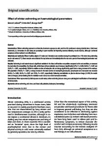
bar. Grinding was performed using waterproof SiC abrasive papers P-120, P-240, P-400, P-800, P-1000, P-1500 and P-2000 with abundant amounts of water. Polishing was performed using Al2O3 suspensions with the average particle diameter of 1 μm. The microstructural and morphological properties of the Al/Cu bimetallic joints were examined with a scanning electron microscope (SEM). The SEM analysis was performed at the Faculty of Mining and Geology at the University of Belgrade using a JEOL JSM–6610LV microscope connected to an INCA350 energy-dispersive-spectroscopy unit for the X-ray analysis (EDS). The electron-acceleration voltage applied during the examination was 20 kV, while the electron source was a filament made of tungsten. For observing a possible presence of porosity, secondary electrons were used, while the differences in the chemical content were observed using back-scattered electrons and EDS analyzers. Prior to the SEM-EDS analysis, all of the samples were cleaned in ethanol and acetone using an ultrasonic bath, with the aim of eliminating the residual impurities from the previous phases of the sample preparation. 3 RESULTS AND DISCUSSION In the friction-welding procedure, the bond between Al and Cu is made due to the interdiffusion of the atoms belonging to these metals through the Al/Cu border surface. In this paper, the interdiffusion was detected with the EDS analysis. It was noticed that Al and Cu do not diffuse each other to the same extent; at the same distance from the interface, the Cu concentration in the Al basis was always larger than the Al concentration in the Cu basis (Figures 4a and 4b). The most probable reason for the larger concentration of Cu is the fact that the activation enthalpy of the Cu bulk diffusion in Al (Q = 136 kJ/mol)17 is smaller than the one required for the Al diffusion in Cu (Q = 165 kJ/mol).18 3.1 Effects of the speed With an increase in the distance from the rotation axis, the speed also increases. The points at large distances from the rotation axis cross longer distances because they have longer routes than the points closer to the axis (s = r·j/2·p) and thus a greater wear of the con-
Figure 4: EDS analysis along the axis of an Al/Cu sample Slika 4: EDS-analiza vzdol` aksialne osi vzorca Al/Cu
91
V. D. MILA[INOVI] et al.: EFFECTS OF FRICTION-WELDING PARAMETERS ON THE MORPHOLOGICAL PROPERTIES ...
tact surfaces occurs at the large distances from the rotation axis. Figures 5a to 5c show the appearance of the Al/Cu interface of sample 1. By comparing Figure 5a, where the appearance of the interface close to the rotation axis is shown, with Figure 5b, where the appearance of the interface at the mid-distance between the rotation axis and the sample edge is shown, and Figure 5c, where a joint close to the sample edge is shown, the trend of an increased wear of the surface roughness at the copper part, caused by the lathe preparation of the contact surfaces, can be clearly seen. In Figures 5d to 5f the appearance of the interface at the mid-distance between the axis and the sample edge and close to the edge of sample 3, produced under a different regime, is shown. For this sample, the trend of a decreasing surface roughness at the interface, from the rotation axis towards the sample edge, was noticed, proving that such a phenomenon does not depend on the
Figure 5: Appearance of the longitudinal cross-section of an Al/Cu bimetallic joint produced by friction welding: a) appearance of the joint of sample 1 close to the rotation axis, b) appearance of sample 1 at the mid-distance between the rotation axis and the sample edge, c) appearance of the sample 1 joint very close to the sample edge, d) appearance of sample 3 close to the rotation axis, e) appearance of sample 3 at the mid-distance between the rotation axis and the sample edge, f) appearance of sample 3 very close to the sample edge Slika 5: Izgled vzdol`nega prereza bimetalnega spoja Al/Cu, izdelanega s tornim varjenjem: a) izgled spoja vzorca 1, blizu osi rotacije, b) izgled vzorca 1 na sredini med rotacijsko osjo in robom vzorca, c) izgled spoja v vzorcu 1, blizu roba vzorca, d) izgled vzorca 3, blizu rotacijske osi, e) izgled vzorca 3 na sredini razdalje med osjo rotacije in robom vzorca, f) izgled vzorca 3, blizu roba vzorca
92
regimes of the applied friction-welding parameters, but instead, it is a typical occurrence in the friction-welding process. 3.2 Effects of the operating pressure The aim of the operating pressure is to provide friction for producing the heat necessary for the interdiffusion of the Al and Cu atoms as well as for realizing the Al/Cu bimetallic connection.5 In Figures 6a and 6b, representative microstructural presentations of the Al/Cu bimetallic-joint morphologies are given for the middle and peripheral parts of sample 1, produced by the effects of the operating pressure of PR=32 MPa in the period of tR = 1.5 s, without the application of the forging pressure (PU = 0, tU = 0). Figures 6c and 6d show the morphologies of the joint at the middle and peripheral parts of sample 2, respectively, produced with the operating
Figure 6: Appearance of the longitudinal cross-section of an Al/Cu bimetallic joint produced by friction welding: a) appearance of the joint of sample 1 close to the rotation axis, b) appearance of sample 1 very close to the sample edge, c) appearance of the sample 2 joint close to the rotation axis, d) appearance of sample 2 very close to the sample edge, e) appearance of sample 3 close to the rotation axis, f) appearance of sample 3 very close to the sample edge, g) appearance of sample 4 close to the rotation axis, h) appearance of sample 4 very close to the sample edge Slika 6: Izgled vzdol`nega prereza bimetalnega spoja Al/Cu, izdelanega s tornim varjenjem: a) izgled spoja vzorca 1, blizu rotacijske osi, b) izgled spoja vzorca 1, blizu roba vzorca, c) izgled spoja vzorca 2, blizu rotacijske osi, d) izgled spoja vzorca 2, blizu roba vzorca, e) izgled vzorca 3, blizu rotacijske osi, f) izgled vzorca 3, blizu roba vzorca, g) izgled vzorca 4, blizu rotacijske osi, h) izgled vzorca 4, blizu roba vzorca Materiali in tehnologije / Materials and technology 50 (2016) 1, 89–94
V. D. MILA[INOVI] et al.: EFFECTS OF FRICTION-WELDING PARAMETERS ON THE MORPHOLOGICAL PROPERTIES ...
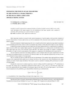
pressure, increased by 50 % when compared to the operating pressure for sample 1. By comparing the morphologies of the joint presented in Figures 6a and 6b with the morphologies presented in Figures 6c and 6d, it is noticeable that the roughness of the interface, resulting from the lathe preparation of the contact surfaces of sample 2, is slightly lower than the roughness for sample 1. This indicates that the increase in the operating pressure of up to 50 % during the rotation without forging did not significantly affect the change of the original morphology of the joint. The reason for this is the fact that the applied operating pressure was most probably lower than the pressure required for causing the deformation and change of the Al/Cu interface shape in the frictionwelding process. It should also be mentioned that the operating pressure, increased by 50 % reached 48 MPa, while the yield strength required for the deformation of pure Cu within an interval of 300–400 °C was of a similar order of magnitude (Figure 7).19 This means that the applied operating pressure could, in theory, deform the pure copper at the temperatures reached during the frictionwelding process. However, the purity of the Al/Cu joint probably exceeds the mentioned strength of the pure Cu since the material in the vicinity of the joint most probably becomes stronger due to the dissolution in the process of friction welding.20 The strengthening caused by the dissolution occurs due to the interdiffusion of the Al and Cu atoms, as proven to occur in the process (Figure 4). It is known that the substitutional solid solutions with a face-centered cubic lattice, such as the solid Cu solution in Al and Al in Cu, show a prominent dependency on the strengthening by dissolution, even at increased
Figure 7: Changes in the yield-strength values of copper and its alloys depending on the temperature19 Slika 7: Sprememba vrednosti meje te~enja pri bakru in njegovih zlitinah, odvisno od temperature19 Materiali in tehnologije / Materials and technology 50 (2016) 1, 89–94
temperatures, since the dissolved atoms affect the thermal component of the Peierls-Nabarro stress.20 Aside from this, it should be mentioned that the effect of the strengthening by dissolution also significantly depends on the atomic size, the relative size of the modulus of elasticity, as well as on the relative valence.20 In Figure 4, it can be noticed that the amount of dissolved atoms increases towards the interface, meaning that the effect of the strengthening by dissolution was the largest precisely on the interface of the Al/Cu joint. To define the friction-welding parameters, due to which the interface is deformed and a joint without the lathe-induced roughness is obtained, in addition to the operating pressure (PR), further examinations also included the additional effect of the forging pressure (PU). The additional introduction of the forging pressure PU that is significantly larger than the pure-Cu yield strength was necessary for causing the change in the Al/Cu interface within a short interval, which is longer than in the case when friction welding is performed under the operating-pressure effects.
3.3 Effects of the forging pressure The forging pressure during the continuous friction welding starts to apply at the moment of the termination of the rotation.10 Its role is to squeeze out all the impurities from the bonding area and to create a strong bond. Figures 6e and 6f show the formations of the bond of sample 3 in the center and very close to the sample edge. The production regime of sample 3 is different from the sample 2 regime: after the termination of the operatingpressure effects PR, the forging-pressure effects of PU = 160 MPa start to be effective in a duration of tU = 2 s. By comparing Figure 6e with 6c and Figure 6f with 6d, a significant decrease in the roughness of the Al/Cu interface is noticed. Even though the operating pressure did not significantly affect the morphology of the joint, it is evident that it provides a sufficient amount of heat by friction, causing a noticeable change in the shape of the Al/Cu bimetallic joint forged under the pressure of 160 MPa. Figures 6g and 6h show the morphology of the sample 4 joint formed in the middle and peripheral parts relative to the rotation axis. Sample 4 was produced in a time twice as long as the time for the forging-pressure effects of tU = 4 s spent for obtaining sample 3. When comparing Figures 6g and 6h to Figures 6e and 6f, an almost complete absence of the roughness of the Al/Cu interface is noticeable in Figures 6g and 6h. This confirms the importance of the forging time as in the duration of tU = 4 s a much larger deformation of the Al/Cu interface is formed than under the forging-pressure PU effects in the duration of tU = 2 s. 93
V. D. MILA[INOVI] et al.: EFFECTS OF FRICTION-WELDING PARAMETERS ON THE MORPHOLOGICAL PROPERTIES ...
4 CONCLUSIONS By increasing the distance from the rotation axis, the wear of the contact surfaces increases as well. Such an occurrence is noticed in various combinations of friction-welding parameters, thus proven to be a property of the process. The effect of the operating pressure of 48 MPa does not significantly affect the shape of the Al/Cu interface during the first phase of bonding, but it provides a sufficient amount of heat for the interdiffusion of the atoms of the Al and Cu metals, taking place in short-term intervals of the friction-welding process. The combined effect of the operating pressure of 48 MPa and the forging pressure of 160 MPa changes the shape of the Al/Cu interface. The forging time for the combined effect of the pressures significantly affects the morphology of an Al/Cu joint within a very narrow time interval. After 2 s of forging, the superficial roughness caused by the lathe preparation is still obvious, but immediately after 4 s of forging, the Al/Cu interface becomes almost completely flat, i.e., without the presence of the roughness caused during the lathe preparation of the surfaces. 5 REFERENCES 1
http://www.mms-jagodina.com http://www.feman.net 3 http://www.elliottelectric.com 4 http://www.marel.rs 5 N. Ratkovi}, A. Sedmak, M. Jovanovi}, V. Lazi}, R. Nikoli}, B. Krsti}, Quality Analysis of Al-Cu Joint Achieved by Friction Welding, Technical Gazette, 16 (2009) 3, 3–7 2
94
6
W. Kinley, Inertia Welding: Simple in Principle and Application, Welding and Metal Fabrication, (1979), 585–589 7 N. I. Fomichev, The Friction Welding of New High Speed Tool Steels to Structural Steels, Welding Production, (1980), 35–38 8 K. G. K. Murti, S. Sundaresan, Parameter Optimisation in Friction Welding Dissimilar Materials, Metal Construction, 15 (1983) 6, 331–335 9 M. Sahin, Friction Welding of Different Materials, UNITECH – International Scientific Conference, Bulgaria, Gabrovo, 2010, 131–134 10 M. Sahin, C. Misirli, Mechanical and Metallurgical Properties of Friction Welded Aluminium Joints, Aluminium Alloys - New Trends in Fabrication and Applications, InTech, Rijeka 2012, 277–300, doi:10.5772/51130 11 R. N. Shubhavardhan, S. Surendran, Friction Welding to Join Dissimilar Metals, International Journal of Emerging Technology and Advanced Engineering, 2 (2012) 7, 200–210 12 M. J. Freiría Gándara, Aluminium: The Metal of Choice, Mater. Tehnol., 47 (2013) 3, 261–265 13 G. Papadimitropoulos, N. Vourdas, V. Em Vamvakas, D. Davazoglou, Deposition and Characterization of Copper Oxide Thin Films, Journal of Physics: Conference Series, 10 (2005), 182–185, doi:10.1088/1742-6596/10/1/045 14 P. Keil, D. Lützenkirchen-Hecht, R. Frahm, Investigation of Room Temperature Oxidation of Cu in Air by Yoneda-XAFS, AIP Conference Proceedings, 882 (2007), 490–492, doi:10.1063/1.2644569 15 V. I. Vill, Friction Welding of Metals, AWS, New York 1962 16 M. Sahin, Joining of Aluminium and Copper Materials with Friction Welding, International Journal of Advanced Manufacturing Technology, 49 (2010) 5–8, 527–534, doi:10.1007/s00170-009-2443-7 17 E. A. Brandes, G. B. Brook, Smithells Metals Reference Book, 7th ed., Butterworth-Heinemann, Oxford 1992, 13.16 18 D. R. Askeland, P. P. Fulay, The Science and Engineering of Materials, 5th ed., Thomson, New York 2006, 152 19 M. Li, S. J. Zinkle, Physical and Mechanical Properties of Copper and Copper Alloys, Comprehensive Nuclear Materials, 4 (2012), 667–690, doi:10.1016/B978-0-08-056033-5.00122-1 20 \. Drobnjak, Fizi~ka Metalurgija – Fizika ^vrsto}e i Plasti~nosti 1, TMF, Beograd 1990, 207–215
Materiali in tehnologije / Materials and technology 50 (2016) 1, 89–94