Journal of Fluorescence, Vol. 10, No. 1, 2000
Effects of Internal Rotations on the Time-Resolved Fluorescence in a Bichromophoric Protein System Under the Energy Transfer Interaction1 Fumio Tanaka2 Received August 31, 1998; accepted August 24, 1999
Effects of internal rotations of chromophores under the energy transfer interaction in proteins on the time-resolved fluorescence were examined by numerical calculations. Expressions used for the calculations are based on the approximations that the energy transfer takes place according to ¨ Forster’s mechanism and the rotational motions of the energy donor and acceptor along the surfaces of cones are described by a set of rotational diffusion equations. The intensity decay of the donor depended a little on the rotational diffusion coefficient of the donor in some cases, while that of the acceptor did very little. Anisotropy of the donor decayed faster as the diffusion coefficient of the donor increased. Anisotropy decay of the acceptor markedly depended not only on the mutual configuration of the pair in the protein, but also on the diffusion coefficient of the donor. The dependence of the time-resolved fluorescence on the diffusion coefficient of the acceptor was not as great as that of the donor.
KEY WORDS: Energy transfer in protein; internal rotations of donor and acceptor; time-resolved fluorescence.
INTRODUCTION
fluorescence of the donor and acceptor with rotational freedom. The theory of the time-resolved fluorescence of fluorophores under the energy transfer interaction has been reported in many works [6–14]. In the previous work [15] we derived theoretical expressions for the time-resolved fluorescence of the energy donor and acceptor in a spherical protein, where both the donor and the acceptor possess rotational freedom around fixed axes in the protein. In the present work we have examined the effects of the rotational diffusion coefficients on the time-resolved fluorescence of both donor and acceptor in some model systems.
Energy transfer interaction has been frequently observed in proteins [1,2], and used to determine the distances between chromophores in the proteins [2], ¨ assuming Forster’s mechanism for the transfer rate [3]. However, a certain arbitrariness cannot be avoided because of an orientation factor to determine the exact distance [4]. The orientation factor depends not only on the mutual configuration of a pair of the energy donor and acceptor in the proteins, but also on the motional freedom of the chromophores in proteins. Recent experimental observations have revealed that chromophores as aromatic amino acid residues possess an appreciable freedom of internal rotation [5]. Accordingly, it is required to work on the theoretical expressions of time-resolved
1 2
DIFFUSION EQUATIONS FOR THE ROTATIONAL MOTIONS OF DONOR AND ACCEPTOR
This work is dedicated to the late Professor Gregorio Weber. Mie Prefectural College of Nursing, Yumegaoka 1-1-1, Tsu 514-1116, Japan. Fax: 181-59-233-5640. e-mail:
[email protected]
Transition moments of absorption and emission of both donor and acceptor were assumed to be identical 13 1053-0509/00/0300-0013$18.00/0 q 2000 Plenum Publishing Corporation
14
Tanaka
here. The transition moments of donor and acceptor are expressed in polar coordinates by m1(d1, f1) and m2(d2, f2), respectively. f1 and f2 are rotational angles of the donor around the z1-axis and the acceptor around the z2axis, respectively. Coordinate systems of the donor and acceptor are represented by (x1y1z1) and (x2y2z2), respectively. The entire protein molecule was assumed to be spherical. The distance between the center of the donor and that of the acceptor is represented by the vector R(RxRyRz). The configuration probability of the donor, r1(ucf1t), was described by the following diffusion equation [15]: r1(ucf1t) 5 2k1r1(ucf1t) 1 D Lr1(ucf1t) t 1 D1 ?
#
2p
2r1(ucf1t) 2 r1(ucf1t) f21 df2kt(f1f2)r2g (f2t)
(1)
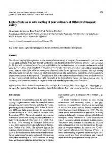
reported in the previous work [15]. In the present systems we have assumed that the distribution of the transition moment of absorption of the acceptor in the ground state is random at the instant of the excitation of the donor. Figure 1 shows the molecular arrangement of both chromophores in a protein. The transition moments of m1 and m2 rotate around the z1- and z2-axes along the surfaces of the cones with definite angles of d1 and d2, respectively. It is also assumed that the distance vector, R, between center of the donor and that of the acceptor molecules is along the y1-axis. Time-dependencies of the intensity and anisotropy are expressed as eigenvalues and eigenvectors of Hill functions [15] with infinite dimensions. Here we approximated the Hill functions with determinant of 41 dimensions.
TIME-RESOLVED FLUORESCENCE OF THE DONOR AND ACCEPTOR IN SOME MODEL SYSTEMS
0
where k1 is the rate constant of emission of the donor without energy transfer interaction. L is Laplacian for rotational motion of the spherical entire molecule. Diffusion coefficients of rotational motion of the spherical molecule and the internal rotations of the donor are denoted D and D1, respectively. Rate of energy transfer is represented by kt(f1f2). r2g(f2t) is a distribution function of f2 of the acceptor in the ground state. The configuration probability of the acceptor was described by Eq. (2) [15]. r2(ucf2t) 5 2k2r2(ucf2t) 1 D L r2(ucf2t) t 1 D2
r2(ucf2t) 1 f22 2
#
2p
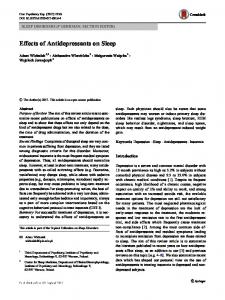
First we examine the time-resolved fluorescence when the z2-axis is in the plane perpendicular to R. Figure 2 shows the time-resolved fluorescence anisotropy of the donor at d1 5 608, d2 5 308 and b 5 908. In this case the rotational axis of the acceptor is perpendicular to that of the donor. The values of the rotational diffusion coefficient of the donor in units of ps21 are indicated in
(2)
df1r1(ucf1t)kt(f1f2)
0
where k2 is the rate constant of acceptor emission. The diffusion coefficient of internal rotation of the acceptor is represented by D2. ¨ kt(f1f2) is represented as Eq. (3) according to Forster [3]. kt(f1f2) 5 k(f1f2)2k1
6
1 2 R0 R
(3)
where R0 and R are the critical transfer distance and magnitude of R, respectively. The explicit form of k(f1f2)2 is given in the previous work [15]. METHOD OF CALCULATIONS Time-resolved fluorescence of both donor and acceptor was calculated with the theoretical equations
Fig. 1. Molecular geometry of donor and acceptor in protein. Transition moments of the energy donor and acceptor are denoted by m1 and m2, respectively, where the transition moments of absorption and emission were assumed to be identical. The transition moment of the donor rotates around the z1-axis along the surface of a cone with a half angle of d1, and that of the acceptor around the z2-axis along the surface of a cone with a half angle of d2. R represents the distance vector between the center of the donor and that of the acceptor, and is along y1-axis. The z2-axis is in the plane perpendicular to R, or parallel to R. b is the angle between the z82-axis (parallel to the z1-axis) and the rotational axis of z2.
Effects of Internal Rotations on Energy Transfer in Proteins
15
Fig. 2. Anisotropy decays of the donor at b 5 908. The z2-axis is in the plane perpendicular to R. The rate constant of the emission of the donor without the energy transfer was 0.01 ps21, and that of the acceptor, 0.02 ps21. The ratio of the absolute value of R and a critical transfer distance, R0, was 1. The rotational diffusion coefficients of the acceptor, D2, and the entire protein molecule, D, were 0.01 ps21 and 0.001 ps21, respectively. The values of D1 in the inset are indicated in units of ps21. d1 5 608 and d2 5 308.
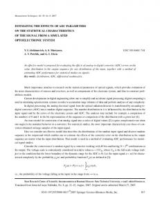
the inset in Fig. 2. The other parameters used for the calculations are indicated in the figure caption. The decays were apparently two-exponential functions. The fast decays show the depolarization by internal rotation of the donor, and slower ones by the spherical entire molecule [16,17]. Figure 3 shows the anisotropy decays
of the acceptor. Although the absolute values of anisotropy were very little, the profile of the decay changed drastically with the values of D1. When the internal rotation of donor is slow, the anisotropy increased slowly from negative to positive values and then decayed to zero after attained the maxima. As the internal rotation
Fig. 3. Anisotropy decays of the acceptor at b 5 908. Parameters used for the calculations were the same as those in Fig. 2. The values of D1 in the inset are indicated in units of ps21.
16
Tanaka
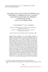
becomes faster, the anisotropy increased more rapidly from negative values to positive maxima. On the other hand, the intensity decays of the donor and acceptor changed little with D1. When the diffusion coefficient of the acceptor (D2) was changed, the intensity decays of the donor and acceptor, and also the anisotropy decays of the donor, depended little on D2. The effect of D2 on the anisotropy decays of the acceptor is shown in Fig. 4. In this case the value of D1 was 0.01 ps21 and the other parameters are the same as those in Fig. 3. Figure 5 shows the dependence of the intensity decay of the donor on D1, when b 5 458. The other parameters are the same as those m Figs. 2. The intensity decayed a little faster as the value of D1 increased. The intensity decay of the acceptor was also modified a little with D1. The anisotropy of the acceptor was initially positive and decayed to negative minima, then increased to zero (Fig. 6). The profile of the anisotropy decays of the acceptor in this case is in contrast with that in Fig. 3, only by a change from b 5 08 to 458. Figure 7 shows the anisotropy decay of the acceptor when b 5 08. The other parameters are the same with those in Fig. 2. In this case the rotational axis of the acceptor (z2-axis) is parallel with that of the donor (z1axis), and so the absolute values of anisotropy were relatively high compared with those above. The profile of the decays was similar to that in Fig. 6. Here we examine the change in the time-resolved fluorescence when the cone angle of internal rotation of
the donor becomes narrower. Figure 8 shows the anisotropy decays of the acceptor at d1 5 308 and b 5 08. The other parameters are the same as those in Fig. 7 or Fig. 2. The decay profile changed markedly from that in Fig 7. In this case the anisotropy decayed monotonously and did not show any minima as in Fig. 7. Next we examine the effect of internal rotation of the donor on the time-resolved fluorescence when the rotational axis of the acceptor (z2-axis) is along R. Figure 9 shows the anisotropy decays of the acceptor at d1 5 608, which is compared with Fig. 3. Although in both cases the angle between the rotational axis of the donor and that of the acceptor is right angle with each other, in Fig. 3 the z2-axis is perpendicular to R, while it is parallel to R in Fig. 9. The anisotropy monotonously increased to zero from the negative initial values in Fig. 9, which is quite different from that in Fig. 3.
DISCUSSION The effects of the internal rotations of the energy donor and acceptor in a protein system on the timeresolved fluorescence were examined for some model systems, where the distance vector between the donor and the acceptor is along the y1-axis, by numerical calculations. Equations used for the calculations of the timeresolved fluorescence are given in the previous work [15] ¨ by assuming Forster mechanism [3] for the excitation transfer and Markov process for the internal rotations of
Fig. 4. Anisotropy decays of the acceptor upon varying the diffusion coefficient of internal rotation of the acceptor at b 5 908. The value of D1 was 0.01 ps21. The values of D2 in the inset are indicated in units of ps21. The other conditions were the same as those in Fig. 2.
Effects of Internal Rotations on Energy Transfer in Proteins
17
Fig. 5. Intensity decays of the donor at b 5 458. The conditions for the calculations were the same as those in Fig. 2. The values of D1 in the inset are indicated in units of ps21.
both donor and acceptor and for the spherical protein molecule. Recently the time-resolved fluorescence anisotropy was theoretically treated in a system of identical chromorphores with the energy transfer interaction, by means of a stochastic Liouville equation. In these works the relaxation processes from the higher excited states of the composite molecules as well as the rotational-dependent orientation factor have been explicitly considered from
the point of view of the non-equilibrium statisticalmechanics. The method may be useful when the interaction is so strong that the energy transfer takes place before the excited state of the donor attains the fluorescent state. In many proteins the internal rotations of aromatic amino acid residue as tryptophan or tyrosine were rather slow (sub-nanoseconds) [5]. Accordingly, the energy transfer is considered to take place after the excited state attains the equilibrium state. In the earlier works the observed
Fig. 6. Anisotropy decays of the acceptor at b 5 458. The conditions for the calculations were the same as those in Fig. 2. The values of D1 in the inset are indicated in units of ps21.
18
Tanaka
Fig. 7. Anisotropy decays of the acceptor at b 5 08. The rotational axis of the acceptor is parallel with the z1-axis. The conditions for the calculations were the same as those in Fig. 2. The values of D1 in the inset are indicated in units of ps21.
time-resolved fluorescence intensity and anisotropy of tryptophan were simultaneously reproduced in erabutoxin b [18] and Streptomyces subtilisin inhibitor [19] with the theoretical equations derived by assuming a Markov process for the internal rotations of tryptophan 2[0]. These results support that the Markov approximation used in
the present work is appropriate for the internal motions of aromatic amino acid residues in proteins. The decay profile of the anisotropy of acceptor markedly changed not only by the mutual configuration of the donor and acceptor, but also by the diffusion coefficient of the internal rotation of the donor, whereas the intensity
Fig. 8. Anisotropy decays of the acceptor at b 5 08. d1 5 308 and d2 5 308. The rotational axis of the acceptor is parallel with the z1-axis. The other conditions for the calculations were the same as those in Fig. 2. The values of D1 in the inset are indicated in units of ps21.
Effects of Internal Rotations on Energy Transfer in Proteins
19
Fig. 9. Anisotropy decays of the acceptor with the rotational axis along R. The parameters used for the calculations were the same as those in Fig. 2. The values of D1 in the inset are indicated in units of ps21.
decay did not change much by these variations. The effect of internal rotation of the donor on the time-resolved fluorescence was enhanced when the cone angle of d1 became wide. In some mutual configurations the intensity decay of the donor was dependent on the diffusion coefficient of D1. The variation of the intensity decay with D1, however, was not so much as that when the acceptor or quencher is assumed to be fixed in the protein [11,18,20]. The dependence of the intensity and anisotropy decays of the donor on the diffusion coefficient of the acceptor was not appreciable in the present models. This may be ascribed to the fact that the distribution in the direction of the transition moment of the acceptor is uniform around the z2-axis in the present approximation, and so the transfer rate is averaged out over f2. The dynamic nature of the protein structure in the time region of picoseconds to sub-nanoseconds has been investigated by means of the time-resolved fluorescence [5] and the method of molecular dynamics simulation [21]. Considering that the anisotropy decay of the acceptor is very sensitive to both the mutual arrangement of the donor and acceptor and the rotational diffusion coefficient of the donor, it is suggested that a precise feature on the protein dynamics can be obtained by analyzing the observed time-resolved fluorescence anisotropy of energy transferring protein systems by the present method.
REFERENCES
1. 2. 3. 4. 5. 6. 7. 8. 9. 10. 11. 12. 13. 14. 15. 16. 17. 18.
19. 20. 21.
I. Z. Steiberg (1971) Annu. Rev. Biochem. 40, 83–114. L. Stryer (1978) Annu. Rev. Biochem. 47, 819–846. ¨ T. Forster (1948) Ann. Phys. 2, 55–75. R. E. Dale and J. Eisinger (1975) in R. F. Chen and H. Edelhoch (Eds.), Biochemical Fluorescence: Concept, Vol. 1, Marcel Dekker, New York, pp. 115–284. J. M. Beechem and L. Brand (1985) Annu. Rev. Biochem. 54, 43–71. R. D. Spencer and G. Weber (1970) J. Chem. Phys. 52, 1654–1663. F. Tanaka and N. Mataga (1979) Photochem. Photobiol. 29, 1091– 1097. A. Szabo (1984) J. Chem. Phys. 81, 150–167. M. N. Berberan-Santos and B. Valeur (1991) J. Chem. Phys. 95, 8048–8055. J. J. Fisz (1996) Chem. Phys. Lett. 262, 495–506. F. Tanaka and N. Mataga (1982) Biophys. J. 39, 129–140. ¨ P.-O. Westlund and H. Wennerstrom, J. Chem. Phys. 99, 6583– 6589. I. Fedchenia and P.-O. Westlund (1994) Phys. Rev. E 50, 555–565. L. B.-A. Johanson, P. Edman, and P.-O. Westlund (1996) J. Chem. Phys. 105, 10896–10904. F. Tanaka (1998) J. Chem. Phys. 109, 1084–1092. Y. Y. Gottlieb and Ph. Wahl (1963) J. Chim. Phys. 60, 849–856. Ph. Wahl and G. Weber (1967) J. Mol. Biol. 30, 371–382. F. Tanaka and N. Mataga (1992) in N. Mataga, T. Okada, and H. Masuhara (Eds.), Dynamics and Mechanisms of Photoinduced Electron Transfer and Related Phenomena, Elsevier, Tokyo, pp. 501–512. F. Tanaka, N. Tamai, N. Mataga, B. Tonomura, and K. Hiromi (1994) Biophys. J. 67, 874–880. F. Tanaka and N. Mataga (1987) Biophys. J. 51, 487–495. M. Karplus and J. A. McCammon (1983) Annu. Rev. Biochem. 52, 263–300.