EFFICIENCY OF SILICON THIN-FILM PHOTOVOLTAIC MODULES WITH A FRONT COLOURED GLASS S. Pélisset1; M. Joly2; V. Chapuis1; A. Schüler2; S. Mertin2 ; V. Hody-Le Caër2; C. Ballif1; L.-E. Perret-Aebi1 1: Ecole Polytechnique Fédérale de Lausanne (EPFL), Institute of Microengineering (IMT), Photovoltaics and thin film electronics laboratory, Breguet 2, 2000 Neuchâtel, Switzerland, email :
[email protected] 2: Ecole Polytechnique Fédérale de Lausanne (EPFL), Solar Energy and Building Physics Laboratory, EPFL-ENAC-IIC-LESO-PB, Station 18, 1015 Lausanne, Switzerland.
ABSTRACT Photovoltaic electricity has already proven its ability to compete with other well established technologies for energy production. The abundant and non-toxic raw materials, the yearly increasing efficiency as well as the production cost of silicon thin-film solar cells getting lower and lower make this technology always more interesting for a wide spread use. Beside the functional features, the size, colour and glass texture of a PV module determine its appearance and aesthetics. In order to be more compliant with the built environment, photovoltaic installations have to be improved in terms of visual rendering, matching of colour of the existing roof-tops and parasitic reflections. The crystalline technology already offers various types of systems with a large choice of shapes, textures and colours as well as “semi-transparent” modules more easily integrated in the roof-tops or facade. By changing the anti-reflective coating (ARC) of a crystalline solar cell, it is possible to modify their colour [1]. However, for thin-film silicon technology the challenge is completely different, and up to now, the only way to modify the module colour is to reduce the thickness of the active layer and consequently its efficiency. Therefore new ways to enhance the visual rendering of the thin-film modules have to be explored. A study led in the frame of the ArchinSolar project [2] has shown that architects are ready to integrate PV modules with enhanced aesthetic aspect, even though there was a 10 % loss in efficiency. The present study shows how new coloured filters can be used to enhance PV modules’ appearance while minimizing power loss, to achieve a better integration in the traditional urban or rural environment. INTRODUCTION The enhancement of aesthetics for a better building integration of solar thermal collectors has already been developed by the use of coloured filters [3]. The challenge of the ArchinSolar project is to develop further these techniques and adapt them to PV modules, for which the requirements concerning the range of light transmission are completely different [4]. In this purpose, a special chemical treatment of the outer side of the novel glass element shall produce a textured or matt appearance while decreasing light reflection. In order to vary the module’s colour, an optically selective filter is applied on the inner side. Minimizing energetic losses, this filter should only reflect a selected part of the incoming radiation. The coloured filters have to be optimized to combine an intense colour with a good light transmission.
Proceedings CISBAT 2011, Lausanne, Switzerland
37
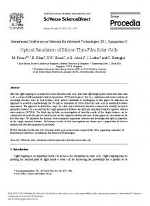
A first version of these selective filters was tested on amorphous silicon (a-Si:H) thin-film modules. Each combination of cell, filters, back-reflector and texturized glass was characterized optically and electrically. Transmission and reflection spectra were recorded in the UV-Visible-NIR range by spectrophotometry and the quantum efficiency and the currentvoltage characteristic were measured.
Figure 1: Sketch of the measured stack METHOD Two different selective filters, reported hereafter as Filter 1 and Filter 2 were tested. They were both orange, filter 1 having a low reflection, while filter 2 was more reflective and its colour appeared more intense. Commercially available a-Si:H mini-modules were used for the measurements. The modules were monolithically inter-connected; therefore, to connect one cell, wires were soldered at the back of the cell nth and n+1st. To get an as low as possible contact resistance with the back ZnO, the wires were soldered with the USS9200 ultra-sonic soldering station from MBR Electronics. The filters were placed on top of the cell covered with an index matching liquid, Immersol 518N from Zeiss, corresponding to the glass and encapsulant indices, to avoid the presence of air between the filters and the glass of the modules. Between the measurements, the different parts of the stack were cleaned in an ultrasonic bath filled with isopropanol. External quantum efficiency was measured with an in-house setup, current-voltage characteristics was measured with a Wacom sun simulator and the transmission and reflection spectra were recorded using a Lambda 900 spectrometer from Perkin-Elmer, with an integrating sphere. RESULTS External Quantum Efficiency measurements External quantum efficiency (EQE) setup allows measuring the amount of charge carrier created at each wavelength with the cell in short circuit. A grating selects the wavelength of the light illuminating the cell and the current is collected through two wires directly soldered on the zinc oxide electrodes. The incident power at each wavelength is reported to the solar spectrum AM1.5, in order to determine the current density in short circuit Jsc, at 1000 W.m-2. Only a small area of the cell was illuminated (2mm2), therefore 3-5 measurements were made for each conditions, moving the sample each time, in order to average the values. The standard deviation of the short circuit current density measured with EQE was below 1% for each sample. For each cell, the measurements were done under 6 different conditions (bare
38
Proceedings CISBAT 2011, Lausanne, Switzerland
cell, cell with white back-reflector (BR) on the back, cell + filter 1 on top, cell + filter 2 on top, cell + BR + filter 1, cell + BR + filter 2). Due to the design of the EQE setup, it was not possible to include the texturized glass in the set of samples. A higher loss due to reflection was observed for the cell + filter condition (see Figure 2) in the blue part of the spectrum as compared to the bare cell condition. The reflection in this region did not participate to the colour of the stack and therefore this part would have to be optimized. The amount of current lost in the blue region was only 0.5% for the filter 1 whereas it was 2.5% for the filter 2. By reducing the reflection of the filter 2 in the blue region, the loss in current density could be reduced to a value around 10%.
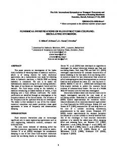
Figure 2: Measurements of the EQE and the losses due to reflection and absorption in the front part of the cell (glass and filters), for the bare cell (plain curves), the cell with the filter 1 (dotted curves) and the cell with filter 2 (dashed curves). Plot on the left corresponds to the cell without back-reflector; plot on the right corresponds to cell with white reflector. Optical simulation of EQE 1-dimension optical simulations of a-Si:H solar cells with filters were performed using the Sunshine software [5] developed by the University of Ljubljana, Slovenia. Simulations allowed us to avoid taking into consideration the power loss due to the module quality and other parasitic electrical effects present in the measurements. Simulation of the bare cell fitted well the measured EQE (see Figure 3).
Figure 3: EQE and 1-R curves for the a-Si:H cell measured (plain curves) and simulated (circles)
Proceedings CISBAT 2011, Lausanne, Switzerland
39
Based on the transmission measurements of the filters, the solar spectrum AM1.5 was transformed and inserted in the simulator. Conditions with and without back-reflector were considered. Due to some imprecision in the calculation, this method overestimated the loss in current. The loss was found to be 3.6 to 4.4% higher than the one measured with EQE (see Table 1 and Table 2). But when those simulated losses were compared to I-V data, the difference was found to be below 3.5%. Even though the losses were different, the trends remained the same; therefore Sunshine could be an interesting tool for the optimization of the filters, before manufacturing. Current-Voltage measurements The I-V characteristics were recorded for the same combinations as described above. The texturized glass was also placed on top of the stack.
Figure 4: I-V curves of a mini-module with filters, back-reflector and texturized glass. The voltage was divided by the number of cells connected. Introducing an additional textured glass on the top of the stack should lead to a decrease in reflection and though an increase in efficiency. However, during the measurements, there was light leakage, due to the thickness of the glass, on the edges of the cell. This was the reason why the loss in current was higher for the I-V measurements than for the EQE measurements. This leakage will be reduced by increasing the area of the module. The relative efficiency loss was below 9.1% for the cell with filter 1 and below 14.4% for the cell with filter 2 (see Figure 4).
Cell + Filter 1
Loss in Jsc from EQE (%)
Loss in Jsc from IV (%)
Loss in Jsc from Simulation (%)
5.4
6.2
9.6
Cell + Filter 1 + Texturized glass Cell + Filter 2
7.7 11.0
12.9
15.4
Cell + Filter 2 + 13.4 Texturized Glass Table 1: Loss in short circuit current when filters and texturized glass are placed on top the cell. The reference is the bare cell.
40
Proceedings CISBAT 2011, Lausanne, Switzerland
Loss in Jsc from EQE (%)
Loss in Jsc from IV (%)
Loss in Jsc from Simulation (%)
6.3
7.8
9.9
Cell + Filter 1 Cell + Filter 1 + Texturized glass Cell + Filter 2
9.0 11.8
13.5
16.0
Cell + Filter 2 + 13.8 Texturized Glass Table 2: Loss in short circuit current when filters and texturized glass are placed on top the cell with back-reflector. The reference is the bare cell with back-reflector. Colour determination The aim of this study was to show the colour changes when adding coloured filters on modules. The CIE (International Commission on Illumination) Yxy colorimetric co-ordinates shown in Figure 5 were evaluated from the pictures of each element, under standard illuminant D65 and standard observer 1931.
Figure 5: Blurred picture and CIE xy co-ordinates of each stack xy values of the different stacks showed that adding the filters allowed to tune the tint to get closer to the colour of a typical roof tile and that the role of the white reflector could also help for a better visual rendering.
Proceedings CISBAT 2011, Lausanne, Switzerland
41
CONCLUSION
This study shows clearly that by using filters 1 and 2, the loss of efficiency is lower than 16%, which is much lower than the 33% considered in the work of Selj et al. for crystalline technology [1]. A module with the filter 1 would be in the acceptable range of efficiency, if we consider the limit of 10% loss in efficiency the architects would accept. For the filter 2, it has been shown above that reducing the reflection in the blue range of the spectrum could reduce the loss in current (and therefore in efficiency) to a value closer to the 10%. For both filters, any absorption will be avoided by tuning finely the deposition parameters. The present study shows us the importance, for a better precision, to consider the simulation of the whole stack instead of combining spectrophotometry measurements and simulation of the cell only. Despite the filters optimization is still needed for better performances as well as the design of others colours, our results are really promising for designing more esthetical modules better adapted for a respectful architectural integration.
REFERENCES 1. J.H. Selj, T.T. Mongstad, R. Søndenå, E.S. Marstein. Reduction of optical losses in colored solar cells with multilayer antireflection coatings. Solar Energy Materials and Solar Cells, In Press, Corrected Proof, 2011. 2. Archinsolar: “Unique and innovative building integration solution”, demonstration project financed by Swiss Electric Research (SER), Competence Center Energy and Mobility (CCEM.CH), Services Industriels Genevois (SIG), Office Fédérale de l’ Energie (OFEN), 04.2010-04.2013. 3. Andreas Schüler, Deepanshu Dutta, Estelle de Chambrier, Christian Roecker, Gregory De Temmerman, Peter Oelhafen, and Jean-Louis Scartezzini. Sol-gel deposition and optical characterization of multilayered SiO2/Ti1-XSiXO2 coatings on solar collector glasses. Solar Energy Materials and Solar Cells, 90(17):2894-2907, 2006. 4. A. Shah (2010, 1st edition). Thin-film Silicon solar cells, EPFL Press isbn 1420066749. 5. Janez Krc, Franc Smole, and Marko Topic. Analysis of light scattering in amorphous aSi:H solar cells by a one-dimensional semi-coherent optical model. Progress in Photovoltaics: Research and Applications, 11(1):15_26, 2003.
42
Proceedings CISBAT 2011, Lausanne, Switzerland