BULLETIN OF THE POLISH ACADEMY OF SCIENCES TECHNICAL SCIENCES Vol. 54, No. 4, 2006
Efficient algorithm for designing multipurpose control systems for invertible and right-invertible MIMO LTI plants ´ S. BANKA and P. DWORAK∗ Institute of Control Engineering, Szczecin University of Technology, 26 Kwietnia St., 71-126 Szczecin, Poland Abstract. In the paper an approach to design of multipurpose control systems is considered. It is presented an universal and efficient algorithm for synthesis of multipurpose control system for proper, invertible and right-invertible multi-input multi-output dynamic (MIMO) plants which can be both unstable and/or non-minimumphase. The developed control systems feature both dynamic (either block or row-by-row) decoupling and arbitrary closed-loop pole placement and zero steady-state errors for regulation or tracking processes in presence of (non-diminishing) disturbances. Key words: multivariable control systems, multipurpose systems, dynamic decoupling, pole assignment, polynomial matrix equations.
1. Introduction The goal of control is to maintain stability of the system and at the same time to satisfy many other requirements in order to achieve high performance of control processes. It is advisably to be able to e.g. enforce dynamic properties for a closed-loop system with simultaneous minimization of overshoots and/or setting time and zeroing steady-state errors [1]. It may be very difficult to realize these requirements especially for complex multi-input multi-output plants, mainly due to coupling of the plant inputs with different outputs. This is why decoupling of the MIMO systems plays a very significant role in designing control systems. It allows us to consider each decoupled loop independently of any other one. When the row-by-row (diagonal) decoupling is applied to the system a set of singleinput single-output subsystems, which are easier to control, is obtained. However dynamic decoupling of MIMO systems is one of the most difficult problems in construction of multivariable control systems especially for non-square (usually rightinvertible) plants which can have non-minimum phase transmission zeros. It is well known in the decoupling theory that some poles of the decoupled (compensated) system, related to the so-called interconnection transmission zeros of the plant, are fixed. These can generate uncontrollable and/or unobservable parts of the closed-loop system. Cancellations of such non-minimum phase zeros (unstable “hidden” modes) make the system unstable. Although the idea of dynamic decoupling for multivariable (MIMO) systems has been considered by many authors since 1960s beginning with [2] and that decoupling problem with stability has been intensively studied in the past (see e.g. [3–8]) open problems still exist. The most of the methods allows some fixed poles to exist in the decoupled system which (if they are unstable) can result in the system instability. Moreover, they are often confined to square plants with minimum phase zeros only. So, in designing of a control system it is crucial to use a ∗ e-mail:
decoupling algorithm which allows us to avoid unstable “hidden” modes and is enough flexible to be able to allow for some other requirements. The developed multipurpose control systems, apart from block (or diagonal) dynamic decoupling, feature both an arbitrary closed-loop pole placement assumed independently for each decoupled part of the system, and zero steady-state regulation or tracking errors in the presence of deterministic disturbances, and reconstruction (or optimal estimation) of the plant’s state vector, if it is inaccessible (and/or noised). The first results which fulfilled the above mentioned requirements were given in [9]. The papers [10,11] expand the results of Wolovich to more general proper invertible and rightinvertible plants with both stochastic and deterministic disturbances. In the paper [11] it was presented an algorithm for designing multipurpose control systems which provides all of the above-mentioned properties of multipurpose control systems for non-square (right-invertible) continuous plants. It makes use of the decoupling method presented previously in [12]. Yet, this algorithm, contains some steps which make it practically useless. However, modifications proposed in [13–15] allow us to return to this algorithm and make it more efficient and numerically reliable. In this paper it is presented a new improved version of the algorithm for synthesis of multipurpose control systems. It is designed for linear m-input l-output both invertible m = l and right-invertible with m > l plants described by proper rational full rank transfer matrix T (s). Plants can be unstable, non-minimum phase or both.
2. Problem statement We consider a controllable and observable linear LTI MIMO model of the plant defined by the state and output equations
[email protected]
429
x(t) ˙ = Ax(t) + Bu(t) + Er(t) y(t) = Cx(t) + Du(t)
(1)
S. Ba´nka and P. Dworak
where x(t) ∈ Rn , u(t) ∈ Rm and y(t) ∈ Rl (m > l) are the state, input and output vectors respectively. The vector r(t) ∈ Rr describes deterministic (non-diminishing) disturbances. In the polynomial matrix approach transfer matrices of all elements of the system are defined by pairs of polynomial matrices either relatively right prime (r.r.p.) for plants, or relatively left prime (r.l.p.) for other elements. Applying this approach, the plant model can be transformed into the relatively prime matrix fraction description in the frequency s-domain as follows −1 y = B1 (s)A−1 r 1 (s)u + A3 (s)B3 (s)¯
(2)
−1 B1 (s)A−1 B+D 1 (s) = C(sIn − A)
(3)
−1 A−1 Er(s). 3 (s)B3 (s) = C(sIn − A)
(4)
where
and
Since the transformed disturbance vector r(s) is included into the transfer matrix the symbol r¯ in the Eq. (2) denotes a “fictitious” impulsive input signal applied to the deterministic disturbance model. Let m3+ (s) denote an unstable and monic polynomial chosen as least common multiplier (l.c.m.) of all unstable poles of the transfer matrix A−1 3 (s)B3 (s). Assuming dynamic (block or diagonal) decoupling of the designed control system we group output and reference signals into “k” blocks according to the partitions y1 (t) y01 (t) .. .. . . y(t) = yi (t) , y0 (t) = y0i (t) , i = 1, 2, ..., k (5) .. .. . . yk (t) y0k (t) where yi (t) ∈ Rli , y0i (t) ∈ Rli ,
k X
li = l.
Fig. 1. Structure of the multipurpose control system
The problem may be solved as follows. The first stage is dynamic (block or diagonal) decoupling of the “inner” part of the control system between the signals q(t) ∈ Rl and y(t) ∈ Rl which are grouped into y1 (t) q1 (t) .. .. . . q(t) = qi (t) and y(t) = yi (t) . . .. .. yk (t) qk (t) with qi (t) ∈ Rli , yi (t) ∈ Rli , i = 1, 2, ..., k. The second stage is to design “k” controllers for “k” decoupled parts of the control system. All goals of the multipurpose control systems can be achieved in a control system structure presented in Fig. 1, which contains the dynamic feedforward compensator, the Luenberger observer with feedback matrix F and the decoupled controller. There may be a lot of ways of designing a multipurpose control system. By employing the above mentioned idea the scheme presented in Fig. 1 may be transformed to the form presented in Fig. 2 with the controller M2−1 (s)N2 (s) and an ‘inner’ part of the system N (s)D −1 (s).
(6)
i=1
Similarly, as in the disturbance vector r(s) case, the reference signal vector yo (s) is generated from the reference model defined by (unstable) strictly proper transfer matrix functions (possible with different transfer functions for each reference signal or for settled “k” groups (blocks) of reference signals) yo (s) = A−1 yo , o (s)Bo (s)¯
(7)
with the impulsive signal input y¯o . Let mi0+ (s) denote monic polynomials adequately chosen for each i-th group of reference signals y0i (t). The goal we pursue is to obtain a decoupled control system in which each part (loop) i = 1, 2, ..., k of a multipurpose system defined by pairs of signals y0i (t), yi (t) ∈ Rli could be controlled independently of other parts j 6= i. Moreover, each part of the system should be designed with individually supposed dynamic properties according to the given class of reference signals y0i (t) ∈ Rli . The same requirements concern the problem of full (diagonal) decoupling of the considered control system. In this case li = 1 and k = l. The structure of such a control system is presented in Fig. 1. 430
Fig. 2. Structure of the MIMO control system in polynomial approach
Once the ‘inner’ part of the system between the signals q and y has been decoupled (diagonal or block), in order to design a control system it is sufficient to solve a set of “k” (unilateral) polynomial matrix equations M2ii (s)Dii (s)+N2ii (s)Nii (s) = ∆ii (s), i = 1, 2, ..., k (8) with respect to the matrices M2ii (s) and N2ii (s) (of minimal degree) for known Dii (s), Nii (s) and for suitable defined (Hurwitz) matrix ∆ii (s) matched to the assumed configurations of the closed-loop control system poles. In order to do that we can employ the usual pole placement technique to synthesise a set of controllers (decoupled controller) for the decoupled system. However, such a way of system designing does not ensure that all design goals will be achieved. In contrast to the above situation, another possibility is to lead a system to the form where both denominator matrices M2ii (s) of controllers and numerator matrices of the “inner” parts of the system Nii (s) in the Eq. (8) are known. Here Bull. Pol. Ac.: Tech. 54(4) 2006
Efficient algorithm for designing multipurpose control systems for invertible and right-invertible MIMO LTI plants the minimal degree solution of a set of k (bilateral) polynomial matrix equations (8) (in the case of diagonal decoupling it is a set of k = l polynomial equations) yields simultaneously both the denominator matrices for the block decoupled “inner” parts of the system Dii (s) and the controller’s numerator matrices N2ii (s). The possibility of defining denominator matrices M2ii (s) allows one to apply the internal model principle and thus satisfy the zero steady state regulation or tracking errors condition. According to the sufficient conditions of that principle given in [16] (see also [17] and [9]), the denominator matrices of the controller can be chosen as M2ii (s) = diag[mii (s)Ili ], for i = 1, 2, ..., k where mii (s) is the l.c.m. of polynomials for all unstable parts of the transfer matrices defined in the Eqs. (4) and (7). So, the second method allows one to synthesize a multipurpose control system which would fulfill all designing goals. There an appropriate control (decoupling) law should be only employed which would match the above procedure. It should allow us to choose the numerator and denominator matrix of the ’inner’ part of the system independently of each other. The method, which after some adjustments could be used, was presented in [13–15]. The feedback law, employed to decouple the system (the linear state variable feedback along with dynamic feedforward) is described by u(s) = G−1 (s)L0 (s)f (s) + G−1 (s)L(s)q(s),
(9)
are proper and F (s)A−1 1 (s) is strictly proper. Without any lose of generality the matrix L0 (s) may be taken as L0 (s) = Im . Then the system has the structure presented in Fig. 3. According to this scheme the considered multipurpose control systems are suitably defined in s-domain by: proper and possible “low-order” transfer matrix G−1 (s)L(s) for the dynamic feedforward compensator, strictly proper (or proper) transfer matrices Q−1 (s)H(s) and Q−1 (s)K(s) for the full (or reduced) order Luenberger observer along with a feedback matrix F and a strictly proper transfer matrix M2−1 (s)N2 (s) for the decoupled controller. All of the above-mentioned polynomial matrix fractions should be relatively left prime (r.l.p.) with nonsingular, row-reduced, denominator matrices. The main problem is to find a method for block decoupling of the “inner” part of the control system (between the signals q and y) for a non-square plant with m > l in such a way as to obtain the transfer matrix Tyq (s) free of cancellation of unstable “hidden” modes. For the applied decoupling law this transfer matrix takes the form Tyq (s)
£ ¤−1 = B1 (s) Q(s)G(s)A1 (s) − K(s)A1 (s) − H(s)B1 (s) × Q(s)L(s) £ ¤−1 = B1 (s) G(s)A1 (s) − F (s) L(s) = N (s)D −1 (s) (11)
with
where f (s) = F (s)xp (s) , F x(t)
(10) m×m
xp (s) is a partial state vector of the plant, G(s) ∈ R[s] , L(s) ∈ R[s]m×l , L0 (s) ∈ R[s]m×m , F (s) ∈ R[s]m×m – polynomial matrices such that G−1 (s)L0 (s) and G−1 (s)L(s)
N (s) = block diag[Nii (s), i = 1, 2, ..., k] ∈ R[s]l×l (12) and D(s) = block diag[Dii (s), i = 1, 2, ..., k] ∈ R[s]l×l . (13)
Fig. 3. Structure of the decoupled control system with inaccessible plant’s state vector Bull. Pol. Ac.: Tech. 54(4) 2006
431
S. Ba´nka and P. Dworak
Fig. 4. Structure of decoupled ’inner part’ of the system for the “augmented” plant
The algorithm starts with determination of the numerator matrix of “inner” part of the system. It is taken as a block diagonal matrix N (s) = block diag[Nii (s), i = 1, 2, ..., k], where particular blocks Nii (s) are g.c.l.d. of columns of i-th rowblock of B1 (s) caused by the partition (5) B11 (s) .. . B1 (s) = B1i (s) (14) . .. . B1k (s) Then B1 (s) takes the form B1 (s) = N (s)B(s).
(15)
As it was presented above the decoupled ‘inner’ part of the system does not have to be stable but it should be free of any unstable cancellations, unobservable and/or uncontrollable, unstable poles. However, if the polynomial matrix ˜ G(s) ∈ R[s]l×l , which is a g.c.l.d. of all columns B(s) defined by the relation ˜ B(s), ˜ B(s) = G(s)
(16)
is not unimodular, and if its zeros lie in the unstable region of the complex plane, the (unobservable) poles of decoupled system corresponding to these zeros are fixed and unstable [12]. These so called ‘interconnection’ transmission zeros cannot be eliminated by a feedforward compensator of zero order. So, in such a case a dynamic compensator is to be used. To remove these unobservable poles we can use the compensation scheme together with an additional dynamic feedforward compensator obtained by augmenting the plant model with a serial dynamic element Ra (s)Pa−1 (s). This element has to be connected to the input of the original plant presented in Fig. 4 and finally “shifted” into the structure of dynamic feedforward compensator [11,12]. After calculating the element Ra (s)Pa−1 (s), the “standard” procedure with an “augmented plant” can be used and a ˜ decoupled system Tyq (s) without fixed poles caused by G(s) is automatically obtained. Of course, this raises the question of how to calculate this additional dynamics. A suitable algorithm was given by Hikita [12] and Ba´nka [11]. Recently it has been modified in [15] to 432
make it more reliable and efficient. This algorithm guarantees free location of all poles of the system and guarantees that all designed elements (parts of the system) are proper (or strictly proper), so they are able to be physically realizable. Thus, we obtain the following design algorithm for the considered block decoupled multipurpose control system.
3. The algorithm Step 1. Given the plant description, derive its transfer matrix B1 (s)A−1 1 (s) using Wolovich’s “structure theorem”. Permute rows of B1 (s), if necessary, to group plant’s outputs y(s) (and y0 (s)). Substitute B1 (s) := P B 1 (s), where P is a permutation matrix. Step 2. Define N (s) = block diag[Nii (s), i = 1, 2, ..., k], where Nii (s) are g.c.l.d. of the columns of i-th rowblock of B1 (s). Calculate B(s) ∈ R[s]l×m such that B1 (s) = N (s)B(s). ˜ Determine G(s) ∈ R[s]l×l , a g.c.l.d. of all columns of ˜ B(s). ˜ the matrix B(s) = G(s) ˜ If G(s) is unimodular (or stable) go to Step 3, else do the following steps: ˜ −1 (s)Ei = Step 2.1. Convert the left to right fractions G −1 ˜ i (s)J˜ (s) for i = 1, 2, .., k with Ei defined by Il = R ii ˜ ˜ 1 (s), ..., R ˜ k (s)] and [E1 , E2 , ..., Ek ]. Define R(s) = [R J˜(s) = block diag[Jii (s), i = 1, 2, ..., k]. ˆ ˆ ∈ R[s]l×m and R(s) ∈ R[s]m×m Step 2.2. Calculate B(s) −1 ˜ ˜ by the left to right conversion R (s)B(s) ˆ R ˆ −1 (s). = B(s) Step 2.3. Convert the right to left fraction of ˆ ad (s)]−1 = R˙ −1 (s)P˙ (s) and set Ra (s) = A1 (s)[R ˙ ˆ ad (s) and R˙ ad (s) are Rad (s) and P¯ (s) = P˙ (s). The R ˆ ˙ adjoints of R(s) and R(s), respectively. Step 2.4. Select U4 (s) ∈ R[s]m×m such that Ra (s)U4 (s) is column-reduced. Substitute Ra (s) := Ra (s)U4 (s). For assumed poles derive Pa (s) = Λ(s) where Λ(s) = diag[λi (s), i = 1, 2, ..., m] with deg[λi (s)] = degci [Ra (s)]. Step 2.5. Derive minimal state space realization of Ra (s)Pa−1 (s) x˙ a (t) = Aa xa (t) + Ba uoa (t) u(t) = Ca xa (t) + Da uoa (t),
(17)
Bull. Pol. Ac.: Tech. 54(4) 2006
Efficient algorithm for designing multipurpose control systems for invertible and right-invertible MIMO LTI plants where xa (t) ∈ Rna , uoa (t) ∈ Rm and u(t) ∈ Rm are vectors of state, input and output of this element respectively. Step 2.6. Connect (in series) additional dynamic element with the plant · ¸ · ¸ A BC a BD a x˙ oa (t) = xoa (t) + uoa (t) 0 Aa Ba £ ¤ y(t) = C DC a xoa (t) + DD a uoa (t), (18) where vector xoa (t) comes from substitution · ¸ x(t) xoa (t) = . (19) xa (t)
Leading coefficient matrix of matrices ∆ii (s) (not necessary diagonal) should satisfy the conditions Γ (∆ii (s)) = Γ r (M2ii (s))Γ c (Dii (s)). Step 8. Given M2ii (s), Nii (s) and ∆ii (s), solve (bilateral) polynomial matrix equations
Step 2.7. Using Wolovich’s “structure theorem” derive the r.r.p. transfer matrix fraction B1 (s)A−1 1 (s) for obtained state space description of the “augmented plant”. Go to Step 2. Step 3. If m = l go to Step 4 else: Derive a unimodular matrix U (s) such that B(s) U (s) = [ Il 0 ]. Let U −1 (s) = [ U1T (s) U2T (s) ]T , where U1 (s) ∈ R[s]l×m , U2 (s) ∈ R[s](m−l)×m . ¯ Substitute B(s) = U2 (s). Step 4. Perform the right to left conversion · ¸−1 B(s) ˜ −1 (s)P˜ (s) to obtain of A1 (s) ¯ =Q B(s) ˜ P˜ (s) ∈ R[s]m×m with Q(s) ∈ R[s]m×m row-reduced. ˜ Determine νj = degrj [Q(s)] for j = 1, 2, .., m and define ν = max{νj }. Given νj and ν, derive Pˆ (s) = diag[sν−νi ]P˜ (s). Let Pˆ (s) = [Pˆ F (s), Pˆ L (s)], where Pˆ F (s) ∈ R[s]m×l and Pˆ L (s) ∈ R[s]m×(m−l) . . . . Define Pˆ F (s) = [P1F (s)..P2F (s).......PkF (s)], where PˆiF (s) ∈ R[s]m×li , i = 1, 2, . . . , k. Step 5. For i = 1, 2, ..., k and j = 1, 2, . . . , li determine degrees d¯ij for diagonal elements dij (s) of Dii (s) from the constraint deg dij (s) = max{degcj PˆiF (s) − ν, 0}. Step 6. Define M2 (s) = block diag[M2ii (s)] = block diag[Ili mi (s), i = 1, 2, ..., k] with polynomials mi (s) chosen as l.c.m. of the unstable and monic polynomials m3+ (s) and mi0+ (s) generated from poles of the unstable parts of the transfer matrices (4) and (7). Denote m ¯ ij = degrj M2ii (s) for i = 1, 2, . . . , k and j = 1, 2, . . . , li . ¯ ij + d¯ij and define deStep 7. Determine δ¯ji = deg δji (s) = m li P grees δ¯i = δ¯ji for determinants of ∆ii (s). Assum-
to obtain ΦN (s) ∈ R[s]m×m with ΦD (s) ∈ R[s]m×m row-reduced. Determine µj = degrj [ΦD (s)], j = 1, 2, ..., m and define µ = max{µj }. ˆN (s) = diag[sµ−µj ]ΦN (s). Given µj and µ, derive Φ ˆ (s) ∈ R[s]m×m such Select an unimodular matrix W ˆ ˆ that ΦN (s)W (s) is column-reduced. Step 10. Determine degrees ¯lj = deg[ˆlj (s)] for j = 1, 2, ..., m from the constraint ¯lj = ˆN (s)W ˆ (s)] − µ, 0}and set L(s) ˆ max{degcj [Φ = ˆ ˆ diag[lj (s)] with lj (s) chosen freely as stable (monic) polynomials suited to the assumed (uncontrollable) poles of the transfer matrix Tyq (s). ¯ ˆ W ˆ (s) to obtain the Step 11. Calculate [L(s), L(s)] = L(s) ¯ matrices L(s) ∈ R[s]m×l and L(s) ∈ R[s]m×(m−l) , ˆ W ˆ (s). the first l and the last m − l columns of L(s) Step 12. Execute right matrix division [L(s)D(s)B(s) + −1 −1 ¯ B(s)]A ¯ L(s) 1 (s) = G(s) − F (s)A1 (s), where m×m G(s) ∈ R[s] is the quotient and −F (s) ∈ R[s]m×m is the remainder. Step 13. If the plant’s state vector is not accessible for direct measurement, in order to design the full order Luenberger observer set the matrix
j=1
ing stable values for poles of the closed-loop system generate the matrices ∆ii (s) with known |∆ii (s)| = δ¯i Q (s − sp ) (independently) for each block of the sysp=1
tem. To avoid any cancelations between ∆(s) and N (s), zeros of each ∆ii (s) and Nii (s) should be disjoint. Bull. Pol. Ac.: Tech. 54(4) 2006
M2ii (s)Dii (s) + N2ii (s)Nii (s) = ∆ii (s) for i = 1, 2, ..., k with respect to Dii (s) and N2ii (s) (of minimal degree). Step 9. Perform the right to left conversion of · ¸−1 D(s)B(s) A1 (s) = Φ−1 D (s)ΦN (s) ¯ B(s)
¯2 (s) = diag[¯ C cj (s)], j = 1, 2, ..., l, where c¯j (s) =
d¯j Q i=1
(s − si ). The si are assumed (stable)
values of poles for the observer and d¯j are observability indices equal to the row degrees d¯j = degrj A2 (s), where A2 (s) is the denominator matrix of the r.l.p. matrix fraction description of the plant’s transfer matrix A−1 (s)B2 (s) = C(sIn − A)−1 B + D. 2 ¯2 (s) to the matrix C2 (s) with the Transform matrix C same (row) structure as A2 (s). Determine the “gain” matrix L of the observer from the equation ˜ T˜L C2 (s) − A2 (s) = S(s) (20) ˜ and T˜ are calculated during r.l.p. (dual) facwhere S(s) torization of the plant’s transfer matrix. 433
S. Ba´nka and P. Dworak
4. Comments on the time domain realization of designed control system ˜ If in Step 2 of the above presented algorithm the matrix G(s) is unimodular, then the feedback matrix F can be determined ˆ directly from the relationship F (s) = F TˆS(s), where Tˆ and ˆ are known. These are calculated in Step 1 during the r.r.p. S(s) factorization of the plant’s transfer matrix (3). ˜ If G(s) is not unimodular and the additional Steps 2.1–2.7 ˆ (which rewere taken, then having (new) matrices Tˆ and S(s) sult from r.r.p. factorization of the “augmented” plant ) derive ˆ matrix Foa from the equation F (s) = Foa TˆS(s). Let · ¸ . Foa = F .. Fa , 21 where F ∈ Rm×n determines the first part of feedback from plant’s state vector and Fa ∈ Rm×na the second part of feedback from the state vector of an additional dynamic element. Then f (t) = [F x(t) + Fa xa (t)] , 22 where x(t) and xa (t) are state vectors of the plant and additional dynamic element, respectively. The additional dynamic element Ta (s) = Ra (s)Pa−1 (s) should be shifted into the feedforward compensator. Then the control law (in s-domain) takes the form · ¸ £ ¤ q(s) −1 uoa (s) = G (s) L(s) Im , 23 f (s) where uoa (s) is an input to the “augmented” plant. Element G−1 (s)L(s) calculated in Steps 11 and 12 of the algorithm may be realised by state and output equations x˙ k (t) = Ak xk (t) + Bk uk (t) uoa (t) = Ck xk (t) + Dk uk (t),
24
where xk (t) ∈ Rnk and uoa (t) ∈ Rm are state and output vectors and · ¸ q(t) uk (t) = , 25 F x(t) + Fa xa (t) is an input vector to the feedforward·compensator.¸Matrices . Bk , Dk may by defined as Bk = Bkp .. Bkm , Dk = · ¸ . Dkp .. Dkm , where Bkp ∈ Rnk ×p , Bkm ∈ Rnk ×m , Dkp ∈ Rm×p and Dkm ∈ Rm×m . Finally the feedforward compensator G−1 (s)L(s) that includes the additional dynamic element Ra (s)Pa−1 (s) may be described by the state and output equations ¸ ¸ · Ak Bkm Fa Bkp Bkm uw (t) xw (t) + Ba Dkp Ba Dkm Bd Ck Aa + Bd Dkm Fa £ ¤ £ ¤ u(t) = Da Ck Ca + Da Dkm Fa xw (t) + Da Dkp Da Dkm uw (t), ·
x ˙ w (t) =
26
where xw (t) and uw (t) come from · ¸ · ¸ xk (t) q(t) xw (t) = , uw (t) = . xa (t) F x(t)
27
Output signal u(t) of this compensator is the input signal to the “original” plant. 434
The state and output equations of the other system elements may be obtained by using any of the well known conversion from mfd to ss methods [18]. So, here we receive “k” controllers (in time domain) for each decoupled block of the system. In the case of using the full order Luenberger observer there will be a “standard” realization of (strictly proper) observer with the “gain” matrix L calculated in Step 13 ˜˙ (t) = (A − LC)˜ x x(t) + (B − LD)u(t) + Ly(t) (28) f (t) = F x ˜(t). It is also possible to design a functional (reduced order) Luenberger observer defined by the matrices Q(s), H(s) and K(s) which satisfy the (unilateral) matrix polynomial equation K(s)A1 (s) + H(s)B1 (s) = Q(s)F (s),
29
m×m
where Q(s) ∈ R[s]
is defined in some “regular” form n1 Q with assumed (stable) polynomial det Q(s) = (s − sj ) j=1
ˆ ˆ and F (s) = F TˆS(s) for known matrices Tˆ and S(s) obtained during factorization of the “original” plant description (3). Then the canonic realization of the (proper) transfer matri. ces Q−1 (s)[K(s) .. H(s) may be converted to the state space description of observer z(t) ˙ = Ao z(t) + Bo u(t) + Lo y(t) f (t) = Fo z(t) + Do y(t)
30
with z(t) ∈ Rn1 (n1 < n), u(t) ∈ Rm , y(t) ∈ Rl and f (t) ∈ Rm , by using any known method. Moreover, in stochastic case the Kalman filter may also be designed in Step 13 by using the matrix C2 (s) obtained from left spectral factorization of ˜ 2 (s)W B ˜2T (−s) = C2 (s)U U T C2T (−s) A2 (s)V AT2 (−s)+B 31 −1 ˜ for (strictly proper) A−1 G, where 2 (s)B2 (s) = C(sIn − A) G ∈ Rn×p is an additional input matrix in the plant’s state description x(t) ˙ = Ax(t) + Bu(t) + Er(t) + Gw(t) y(t) = Cx(t) + Du(t) + v(t).
32
Vectors w(t) ∈ Rp and v(t) ∈ Rl are “white” Gaussian noises with covariance matrices W > 0 and V > 0. Matrix U in Eq. is an orthogonal matrix. Independent zero-mean noises w(t) and v(t) are additional (not measured) stochastic disturbances contaminating inputs and outputs of the plant, respectively. Then the standard realization of the stationary Kalman filter has the same form (28) as the full order Luenberger observer with substitution of a “gain” matrix L := K. This matrix is calculated from Eq. (20).
5. Example In order to illustrate the theoretical considerations an example of design of a multipurpose control system is presented. We choose a plant (of n = 5 order with m = 4 inputs and l = 3 outputs) defined by the following matrices of the state and output equations Bull. Pol. Ac.: Tech. 54(4) 2006
Efficient algorithm for designing multipurpose control systems for invertible and right-invertible MIMO LTI plants
0 10 1 0 0001 10 −2 −1 1 2 1 1 0 0 0 0 1 A= −4 0 2 1 −1 , B = 0 1 0 0 , E = 0 0 , 1 −1 1 0 −2 0 0 1 0 0 0 0 1 0 −1 0 0001 00 0 0 0 0 −1 1000 C = 0 1 0 0 0, D = 0 0 0 0. 0010 0 0000 This plant can be described in the r.r.p. matrix fraction as follows s + 1 −1 5 0 0 2 0, B1 (s) = 1 0 1 10 s + 1 −1 4 1 0 s − 2 1 5 . A1 (s) = 1 −1 s2 − 2 1 −1 0 −2 s It has the poles s1,2 = −1.653 ± i0.994, s3,4 = 1.45 ± i1.156, s5 = 1.404 and one transmission zero so1 = 2. So, the plant is unstable and nonminimum phase. Before the design procedure is started we assume the following: – the control system will be block decoupled with the partition (5) of the output and reference input taken as l1 = 1 and l2 = 2, which allows existing a coupling between signals y2 (t) and y3 (t), – “ramp” reference signal yo1 (t) for the first loop (output y1 (t)) and “step” reference signals yo2 (t) and yo3 (t) for the second block (outputs y2 (t) and y3 (t)), – two different deterministic disturbance signals: a sinusoidal disturbance r1 (t) of frequency 0.25 Hz and constant (step) disturbance signal r2 (t). As the transmission zero of the plant is an interconnection transmission zero, it is necessary to design, by the use of Steps 2.1–2.7, an additional dynamic element Ra (s)Pa−1 (s). Assuming sa = −3 for (one) pole of this additional element, we have obtained 0.147 −0.0587 0.808 −0.018 −0.111 0.231 −0.21 −0.86 Ra (s) = 0.485s − 2.32 −0.413 −1.678 0.708 , −0.595 −0.207 −0.335 0.198 s+3 0 0 0 0 1 0 0 Pa (s) = 0 0 1 0. 0 001 According to the supposed classes of disturbances and reference signals, as well as assumed partition of signals in the system, the “denominator” matrix M2 (s) of the controller was defined in Step 6 as (diagonal) 4 s + 1.5791s2 0 0 . 0 s3 + 1.5791s 0 M2 (s) = 3 0 0 s + 1.5791s Bull. Pol. Ac.: Tech. 54(4) 2006
Assuming the following values of poles in Step 7: – for the first block: s1 = −1, s2 = −1.2, s3 = −1.4, s4 = −1.6, s5 = −1.8, s6 = −2, – for the second block: s7 = −1, s8 = −1.2, s9 = −1.4, s10 = −1.6, s11 = −1.8, s12 = −1, s13 = −1.2, s14 = −1.4, s15 = −1.6, s16 = −1.8, and suc = −1 as an uncontrollable pole of the control system we obtain: – numerator (block) matrix of the controller N2 (s) =
−26.2s3 − 1.236s2 − 22.87s − 4.8 0 0
0 0 12.58s2 − 21.46s + 7.257 −4.195s2 + 7.154s − 2.419 15.54s2 − 10.103s − 4.83 0 – dynamic feedforward compensator G−1 (s)L(s) 000 0 1 0 L(s) = −1 0 1 , 100 G(s) =
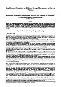
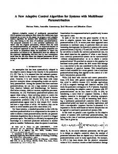
0 0 1 0 0 0.407 −2.636 −0.805 0.97 −0.301 −7.611 0.648 0.147 −0.0587s − 0.4389 0.8087s + 9.23 −0.018s − 0.4 and the feedback matrix −0.18 −1.8 1.82 3.1 −3.45 −1.5 23.72 1.13 −13.7 −12.15 12.57 8.88 F = −14.58 24.47 −21.43 −43.3 85.18 25.06 . 28.58 −33.3 11.43 33.3 −86.18 −18.42 The “gain” matrix of the full order Luenberger observer with the values of its poles assumed as s1 = −3, s2 = −3, s3 = −4, s4 = −5, s5 = −2 is given as 19 −11.5 1 −4 9 0 L = −20 17.5 2 . 19.5 −6.5 1.5 −7 1.5 0 As it is shown in Fig. 5, according to our assumptions there is no interaction between the signal y1 (t) and the both signals y2 (t) and y3 (t). So, the system is (block) decoupled and all of the assumed design objectives are achieved. Control signals u(t) which ensure above presented control processes are given in Fig. 6. 435
S. Ba´nka and P. Dworak
efficient than the ones used so far. This algorithm is also selfcorrecting due to the additional loop, which is applied after Step 2.7 in order to avoid possible errors in calculations performed in Step 2 and Steps 2.1–2.7. Hence, the presented algorithm may become an effective tool in designing multivariable systems.
R EFERENCES
Fig. 5. Results of simulation of the block decoupled control system
Fig. 6. Control signals of the block decoupled control system obtained during simulation
The designed control system (including the plant) has the order ns = n + no + nf c + nc = 22, where no = n = 5 is the order of the Luenberger observer, nf c = 2 the order of the feedforward compensator (including additional dynamic element) and nc = 10 is the order of (block decoupled) controller. The system has one uncontrollable pole suc = −1 in decoupled “inner” part of the system, as well as five uncontrollable poles s1 = −3, s2 = −3, s3 = −4, s4 = −5, s5 = −2 for observer, which define stable “hidden” modes of the system.
6. Conclusions and final remarks In the paper we have presented an universal and improved algorithm for synthesis of multipurpose control system for dynamic plants with the number of inputs being equal or greater than the number of their outputs (invertible and rightinvertible MIMO plants). The proposed algorithm guarantees all assumed designing goals to be achieved and ensures internal stability and internal property for both unstable and nonminimum phase proper plants. Reduced number of operations on polynomials in Steps 2.3–2.4 and improved numerical reliability of calculations by use of the state space method combined with polynomial methods in Steps 2.5–2.7 and in Step 13 makes this algorithm more 436
[1] T.C. Chen, Analog and digital control system design: transfer function, state-space and algebraic methods, Sounders College Publishing, London, 1993. [2] B.S. Morgan, “The synthesis of linear multivariable systems by state variable feedback”, IEEE Trans. on Automatic Control AC-9 (4), 405–411 (1964). [3] J.F. Camart, M. Malabre, and J.C. Martinez Garcia, “Fixed poles of simultaneous disturbance rejection and decoupling: a geometric approach”, Automatica 37, 297–302 (2001). [4] J. Descusse and R. Lizarzaburu, “Triangular decoupling and pole placement in linear multivariable systems: a direct algebraic approach”, Int. J. Control 30 (1), 139–152 (1979). [5] J.C. Martinez Garcia, M. Malabre, J.M. Dion, and C. Commault, “Condensed structural solutions to the disturbance rejection and decoupling problems with stability”, Int. J. Control 72 (15), 1392–1401 (1999). [6] J. C. Martinez Garcia and M. Malabre, “The row by row decoupling problem with stability: a structural approach”, IEEE Trans. on Automatic Control AC-39 (12), 2457–2460 (1994). [7] J. Ruiz, P. Zagalak, and V. Eldem, “On the Morgan problem with stability”, Kybernetika 32 (5), 425–441 (1996). [8] J. C. Zúniga, J. Ruiz-León, and D. Henrion, “Algorithm for decoupling and complete pole assignment of linear multivariable systems”, European Control Conference, Cambridge, UK, 2537(2003). [9] W.A. Wolovich, “Multipurpose controllers for multivariable systems”, IEEE Trans. on Automatic Control 26 (1), 162–170 (1981). [10] S. Ba´nka, “Multipurpose controller design in multivariable stochastic control systems”, Optimal Control Applications and Methods 12 (2), 89–118 (1991). [11] S. Ba´nka, “Multipurpose control systems synthesis for nonsquare multivariable proper plants”, System Science 20 (1), 85– 103 (1994). [12] H. Hikita, “Block decoupling and arbitrary pole assignment for a linear right-invertible system by dynamic compensation”, Int. J. Control 45 (5), 1641–1653 (1987). [13] S. Ba´nka and P. Dworak, “Dynamic decoupling of the right invertible systems”, MMAR, Mi˛edzyzdroje, 279–284 (2004). [14] P. Dworak and S. Ba´nka, “Dynamic decoupling of the right invertible dynamic systems”, Automation 2004, Warszawa, 103– 112 (2004). [15] P. Dworak, Dynamic decoupling of multivariable systems with equal and not equal number of inputs and outputs in polynomial approach, PhD Dissertation, Szczecin University of Technology, Szczecin, 2005, (in Polish). [16] F.M. Callier and C.A. Desoer, Multivariable feedback systems, Springer Verlag, New York, 1982. [17] G. Bengtsson, “Output regulation and internal models – a frequency domain approach”, Automatica 13, 333–345 (1977). [18] Polyx Ltd, Polynomial Toolbox 2.5 for Matlab, Prague, 2003. Bull. Pol. Ac.: Tech. 54(4) 2006