This article has been accepted for publication in a future issue of this journal, but has not been fully edited. Content may change prior to final publication. Citation information: DOI 10.1109/ACCESS.2017.2663758, IEEE Access 1
Efficient Joint User Association and Resource Allocation for Cloud Radio Access Networks M. Awais, A. Ahmed, M. Naeem, M. Iqbal, W. Ejaz, A. Anplagan, H. S. Kim
Abstract—Coordinated scheduling is an efficient resource allocation technique employed to improve the throughput, utilization, and energy efficiency of radio networks. This work focuses on the coordinated scheduling problem for cloud radio access network (CRAN). In particular, we consider the downlink of a CRAN where a central cloud performs the scheduling and synchronization of transmitting frames across the base stations (BSs). For each BS, the transmit frame is composed of several time/frequency slots called resource blocks (RBs). We formulate an optimization problem for joint users to BS association and resource allocation with an objective to maximize the overall network utilization under practical network constraints. The formulated problem is combinatorial and an optimal solution of such a problem can be obtained by performing an exhaustive search over all possible users-to-BSs assignments that satisfy the network constraints. However, the size of search space increases exponentially with the number of users, BSs, and RBs, thus making this approach prohibitive for networks of practical size. This work proposes an interference-aware greedy heuristic algorithm for the constrained coordinated scheduling problem. The complexity analysis of the proposed heuristic is also presented and performance is compared with the optimal exhaustive search algorithm. Simulation results are presented for various network scenarios which demonstrate that the proposed solution achieves performance comparable to the optimal exhaustive search algorithm. Index Terms—Coordinated Scheduling, greedy algorithm, optimal and near optimal scheduling.
I. I NTRODUCTION 5G cellular networks are expected to meet the challenges of increased traffic volume, very high data rates, limited available spectrum, a large number of users, and strict latency requirements [1], [2]. These challenges call for a paradigm shift in the traditional network system architecture. One progressive move to facilitate higher data rates and coverage in urban areas is to migrate from a single high-powered base station (BS) to heterogeneous networks with a large number of small cells of different sizes [3]. However, decreasing the cell size results in large scale inter-BS interference, especially when an underlying strategy is based on full spectrum reuse. In order to M. Awais, A. Ahmed, and M. Iqbal are with the COMSATS Institute of Information Technology-Wah, Wah Cantonment 47040, Pakistan W. Ejaz and A. Anpalagan are with the Department of Electrical and Computer Engineering, Ryerson University, Toronto, ON, M5B 2K3, Canada (email:
[email protected];
[email protected];
[email protected]). M. Naeem is with the COMSATS Institute of Information TechnologyWah, Wah Cantonment 47040, Pakistan, and also with the Department of Electrical and Computer Engineering, Ryerson University, Toronto, ON M5B 2K3, Canada (e-mail:
[email protected]). H. S. Kim is with the Department of Information and Communication Engineering, Sejong University, Seoul, Republic of Korea (Corresponding author) (email:
[email protected])
mitigate this interference, collaborative radio techniques such as coordinated multi-point (CoMP) [4] have been proposed. However, efficient CoMP algorithms such as joint transmission in the uplink and downlink require additional processing as well as a large amount of data transfer between different sites. This results in significant delays and therefore, suffers from a considerable performance loss with traditional X2 interface of LTE architecture [5]. Moreover, power consumption is another major concern for mobile operators since, radio access networks (RAN) constitute a major part of total power consumption of mobile radio networks. To address these issues, a new type of RAN architecture was proposed and called as CRAN which stands for Centralized, Collaborative, Cloud and Clean RAN [6], [7]. CRAN divides the traditional BS into three parts namely remote radio heads (RRHs), the baseband unit (BBU) pool, and a high speed front haul communication link connecting RRH to the BBU cloud pool. In CRAN, various network intensive activities are centralized and moved into the BBU pool in the cloud such as baseband signal processing, precoding matrix calculation, channel state information estimation etc. The cloud is composed of numerous software defined virtual machines which are dynamically configurable, scalable, and re-allocatable on demand. On the other side, RRHs act as the soft relays and can compress and forward the received signals from the BBU. CRAN offers a number of advantages over traditional RAN architectures such as increased resource utilization, lower energy consumption, and decreased inter-base station interference through inter-base station coordination. Most of the recent work on CRAN assumes signal-level coordination at the cloud which includes several joint strategies, i.e., beamforming, resource allocation, and signal processing [8]–[10]. However, such coordination needs collaborative sharing of all data streams among BSs connected to a cloud and thus, requires a large number of high-capacity backhaul communication links. In contrast, we consider the scheduling level coordination which is more practical to implement and at the same time, allows an efficient assignment of users to BSs. We consider the downlink of CRAN where a central processor (cloud) is connected to several single antenna BSs. The cloud is responsible for synchronization of transmitting frames and scheduling of the users across the BSs. The transmit frame of every BS consists of several time/frequency slots called resource blocks (RBs), all maintained at fixed transmit power. To avoid signal level coordination among the BSs, we consider practical constraints, i.e., each user can be connected to at most one BS at a given time. However, a user can occupy multiple RBs belonging to the frame of the same BS. Moreover, a single
2169-3536 (c) 2016 IEEE. Translations and content mining are permitted for academic research only. Personal use is also permitted, but republication/redistribution requires IEEE permission. See http://www.ieee.org/publications_standards/publications/rights/index.html for more information.
This article has been accepted for publication in a future issue of this journal, but has not been fully edited. Content may change prior to final publication. Citation information: DOI 10.1109/ACCESS.2017.2663758, IEEE Access 2
RB can serve one and only one user at a time. Under fixed power transmission and above mentioned practical constraints, the problem of assigning users to BSs becomes a discrete optimization problem whose objective is to maximize a generic network-wide utility function. Such a problem can be solved by an exhaustive search over all possible candidate assignments (that satisfy practical constraints) of users to RBs. However, the exhaustive search is prohibitive for practical networks as the size of search space increases exponentially with the number of users, BSs, and RBs. A. Related Work A number of published works on scheduling are based on a per-assigned association of users and BSs [11], [12]. The work in [11], proposed a classical proportionality fair scheduling on a per-BS basis. The proposed scheme optimizes the user schedule, beamforming vectors, and power spectra jointly while taking into account the inter-cell and intra-cell interference and fairness among the users. In [12], the authors proposed a coordinated scheduling technique for soft frequency reuse based wireless backhaul networks. The problem setup is a simple linear assignment problem as it assumes an equal number of users and RBs. The authors further showed that this problem can be solved by classical auction methodology [13]. The work in [14] proposed a dynamic resource allocation scheme for LTE CRAN. The authors modeled the resource and power allocation problem as a mixed integer linear problem and solved it using a branch and cut algorithm. In [15], the resource allocation problem in CRAN based public safety network (PSN) is modelled as an integer quadratic programming problem. Later on, a Generalized Benders Decomposition (GBD) based OFDM resource allocation algorithm is proposed to find out the solution. In [16], authors proposed a frame work for dynamic coordinated scheduling CoMP in LTE-Advanced networks. The authors proposed that large scale coordination can be obtained through a layered approach in which a cluster of few cells is coordinated in first level, and clusters of coordinated cells are coordinated at a larger scale. The authors modeled both small scale and large scale coordination as optimization problems and then proposed heuristic algorithms for their solution. In [17], authors considered the joint cost effective resource allocation between in CRAN and mobile cloud computing (MCC). In [18], the authors maximized the system capacity in a highly dense CRAN through the usage of CoMP and opportunistic relay activation. Authors in [19] proposed a framework for the resource allocation and admission control problem in a twotier OFDMA cellular network that is composed of a macrocell which is underlaid with CRAN of small cells. The work in [20] proposes a graph theoretic approach for coordinated scheduling problem. In the first step, the authors construct the binary scheduling graph where each vertex represents an association between users, BSs, and RBs. Next, authors formulated the problem as a maximum weight clique problem and proposed a heuristic method for its solution. However, the size of the adjacency matrix of scheduling graph grows quadratically with the product of a number of users, BSs, and RBs.
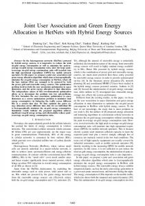
In summary, the above scheduling schemes do not address the scheduling level coordination for practical implementation and efficient assignment of users to BS. B. Contributions The main contributions of this paper are summarized as under: • This work solves the coordinated scheduling problem for the downlink of CRAN for any number of users, BSs, and RBs. The work maximizes the overall network utilization (expressed in terms of sum rate (bits/sec)) under the practical constraints. • The work proposes an efficient heuristic solution based on an interference-aware greedy algorithm. • The proposed solution is computationally efficient and is applicable for dense networks with large number of users, BSs, and RBs. • The accuracy of the proposed solution is validated against a number of practical network scenarios. The simulation results demonstrate that the proposed solution performs very close to the optimal sum rate performance achieved by a brute force exhaustive search algorithm. Moreover, the simulation results also show the efficiency of joint user-BS assignment and resource allocation for CRAN. Notations: Throughout this paper, we use A to denote a matrix, a to denote a vector, and a or A to denote a scallar. Let U be a set, |U| denotes the cardinality of the set U and P(U) denotes its power set. The set B × R denotes the Cartesian product of sets B and R. The rest of the paper is organized as follows, Section 2 describes the system model and problem formulation. Section 3 discusses the proposed solution based on a greedy heuristic. Simulation results are discussed in Section 4. Finally, the paper concludes in Section 5. II. S YSTEM M ODEL AND P ROBLEM F ORMULATION A. System Model Fig. 1 shows a generalized CRAN configuration considered in this work. The CRAN consists of a central cloud which is connected to B single antenna BSs and serves a total of U users. Let B = {b1 , b2 , · · · , bB } denotes the set of all BSs in the network and U = {u1 , u2 , · · · , uU } denotes the set of all users. The transmit frame of each BS consists of R resource blocks as denoted by the set R ={r1 , r2 , · · · , rR }, where each RB is maintained at fixed transmit power Pt . The total number of RBs in the network is Rt = R × B. The cloud manages the scheduling of users as well as synchronization of all transmit frames. The scheduling information is communicated to the BSs through backhaul communication links. The data rate (bits/sec) of a communication link depends on the signal-tointerference plus noise ratio (SINR) seen by the receiver. For a particular receiver located at some point x in space (usually, on the plane), the simplest SINR model is given as
P , (1) N +I where γistheSIN R,Pisthepowerof theincomingsignalof interest,Iisth γ(x) =
2169-3536 (c) 2016 IEEE. Translations and content mining are permitted for academic research only. Personal use is also permitted, but republication/redistribution requires IEEE permission. See http://www.ieee.org/publications_standards/publications/rights/index.html for more information.
This article has been accepted for publication in a future issue of this journal, but has not been fully edited. Content may change prior to final publication. Citation information: DOI 10.1109/ACCESS.2017.2663758, IEEE Access 3
TABLE I L IST OF SYMBOLS AND THEIR DESCRIPTION .
User Base station
Symbol
Cell
U, B, R U ,B,R
Cloud Backhaul link
Transmit Frame Structure r1 rR
Fig. 1. Generalized cloud-enable network consisting of 3 BSs and 10 users. The cloud is connected to BSs through low capacity backhaul communication links.
2
u γbr =
Description
Pbr . |hubr | P 2 , ∀b ∈ B, ∀r ∈ R, ∀u ∈ U Γ(σ 2 + Pb0 r |hub0 r | ) b0 6=b
(2) where Pbr = Pt is the transmit power associated to the RB r of BS b, hubr denotes the fading random coefficient of Rayleigh distribution, σ 2 is the Gaussian noise variance, and Γ is the SINR gap. Orthogonal RBs are assumed in this work as P 2 demonstrated by the denominator term Pb0 r |hub0 r | which b0 6=b
shows that for a user u connected to a RB r of BS b, the interference is only experienced from the RBs with the same index r across different BSs. A list of symbols and their description is given in Table I. B. Problem Formulation In order to avoid signal level coordination among the connected BSs, this work considers two practical constraints for the coordinated scheduling problem for CRAN. • C1: Every user in the network must be connected to atmost one BS at a time, however, can occupy multiple RBs within the transmit frame of that BS. • C2: Every RB in the network must be able to serve at most one user at a time. Given the sets U, B, and R, U × B denotes the set of all possible associations between users and BSs, whereas B × R denotes the set of all possible associations between BSs and RBs. Moreover, A = U × B × R is the set of all possible associations between users, BSs, and RBs and |A| = U · B · Z. The power set of A, i.e., P(A) denotes the set of all possible schedules regardless of the scheduling scheme satisfying constraints C1 and C2 or not.
Set of users, BSs and RBs per BS Total no. of users, BSs and RBs per BS respectively SINR γ σ2 Variance of background noise SINR Gap Γ Pt Maximum transmit power per RB A matrix of dimensions U × B × R which H contains fading coefficients of all possible channels in the system S Matrix of dimensions U × B × R which contains SINR values for all possible channels in the system Matrix of dimensions U × B × R which A contains data rates (bps) of all possible channels in the system a0 sum rate utilization (bps) of a schedule Ω local binary schedule matrix of dimensions U × B × R a Overall network utilization (sum rate in bits/sec) achieved by the algorithm ˆ A Optimal Schedule matrix: a binary matrix whose entry at index u,b,r is 1 if a user u is assigned to RB r of BS b and zero otherwise Λ Vector which represents the indexes of users to be exluded from Argmax function calculation 0 A Matrix which contains all values of A, except the values whom user indexes are stored in Λ [u, b, r] Tupple that represents the indexes of user, BS and RB respectively S\s denotes all elements of set S excluding the element s concatenation operation of vector Λ with [Λ, u] scallar u u A vector of size U that contains the values of a column of A matrix Rayleigh rand() Returns a random number from Rayleigh distribution dec2bin(x, n) function which returns the binary representation of a decimal number x with atleast n bits reshape(x, m, n, p) returns an m-by-n-by-p array whose elements are taken column wise from x 0 Argmax(A ) Function which returns the tupple [u, b, r] 0 for maximum value of A argmax(u) Function which returns the user index of maximum value of vector u
2169-3536 (c) 2016 IEEE. Translations and content mining are permitted for academic research only. Personal use is also permitted, but republication/redistribution requires IEEE permission. See http://www.ieee.org/publications_standards/publications/rights/index.html for more information.
This article has been accepted for publication in a future issue of this journal, but has not been fully edited. Content may change prior to final publication. Citation information: DOI 10.1109/ACCESS.2017.2663758, IEEE Access 4
Each individual schedule S ∈ P(A) can be written as S = {s1 , s2 , · · · , s|s| }, i.e., a set of associations where each individual association si is a tupple (u, b, r) ∈ A. This paper considers the following network-wide utility maximization problem: ˆ = arg max{ S
X
αubr Xubr }
(3)
S∈P(A) u,b,r
subject to X Yub = min( Xubr , 1), ∀(u, b) ∈ U × B
(4)
Algorithm 1 Proposed Greedy Heuristic Algorithm for Coordinated Scheduling 1: Inputs: 2: U, B, R, σ 2 , Γ, Pt 3: U = {1, · · · , U }, B = {1, · · · , B}, R = {1, · · · , R} 4: Initialize: ∀u ∈ U, b ∈ B, r ∈ R ˆ ubr ← 0 5: Hubr ← 0, Subr ← 0, Aubr ← 0, A 6: Λ ← φ, a ← 0 7: Execution Phase 1: ∀u ∈ U, b ∈ B, r ∈ R 8: Hubr ← Rayleigh rand() Pt .|Hubr |2 ! 9: Subr ← Γ. σ 2 +
r
X Yub ≤ 1,
∀u ∈ U,
(5)
Pt .|Hub0 r |2
28:
Aubr ← log2 (1 + Subr ) Execution Phase 2: for x ← 1, U do 0 Aubr ← Aubr , ∀u ∈ U\Λ, b ∈ B, r ∈ R 0 [u, b, r] ← Argmax(A ) 0 0 Aub0 r0 ← 0, ∀ b ∈ B\b, r ∈ R 0 Au0 br ← 0, ∀ u ∈ U\u Λ ← {Λ, u} end for Execution Phase 3: for x ← 1, B do for y ← 1, R do u ← Auxy , ∀ u ∈ U [u] ← argmax(u) Au0 xy ← 0, ∀ u0 ∈ U\u, end for end for Execution Phase 4: ∀u ∈ U, bP ∈ B, r ∈ R ˆ ubr ← 1, if Aubr 6= 0; a ← A A
29:
ˆ a Outputs: A,
10: 11:
b
X Xubr = 1,
P
b0 ∈B\b
∀(b, r) ∈ B × R,
(6)
12: 13:
u
Xubr , Yub ∈ {0, 1}, ∀(u, b, r) ∈ U × B × R
(7)
ˆ Equation (3) shows that the objective is to find a schedule S that achieves a maximum value of network utilization among all feasible schedules (that satisfy C1 and C2) in P(A). The utilization of a schedule S ∈ P(A) is the sum of individual associations in S. To show whether an association si exists or not, Xubr is a binary variable which is 1 if a user u ∈ U is assigned to RB r ∈ R of BS b ∈ B, and zero otherwise, Yub is another random variable which is 1 when a user u is assigned to a BS b and zero otherwise, αubr denotes the utilization of an association si . In this work, αubr is expressed as the data rate (bits/sec) of a communication link established when a user u is assigned RB r of BS b. Mathematically, u αubr = log2 (1 + γbr ).
14: 15: 16: 17: 18: 19: 20: 21: 22: 23: 24: 25: 26: 27:
(8)
The optimal scheduling problem of (3) becomes a sumrate maximization problem. The constrained optimization is performed over variables Xubr and Yub , where (4) and (5) correspond to the constraint C1 while (6) corresponds to constraint C2 of the optimization problem. The optimization problem in (3) to (7) is combinatorial in nature. Finding a global optimum solution to this problem requires to perform an exhaustive search over all possible schedules in P(A) which is clearly infeasible for any network of practical size because |P(A)| = 2|A| . The next section proposes a computationally efficient and accurate heuristic solution for the coordinated scheduling problem given in (3) to (7). III. P ROPOSED H EURISTIC FOR COORDINATED SCHEDULING
We propose a heuristic solution to solve the problem in (3) for coordinated scheduling. The proposed solution is based on an interference aware greedy algorithm. In addition, the problem in (3) is solved using optimal brute force algorithm based on an exhaustive search. The performance comparison of heuristic solution and optimal brute force algorithm is provided to demonstrate the effectiveness of proposed solution. The common inputs to both algorithms are vectors U, B and R which denote the set of all users, BSs, and RBs per base
ubr
station respectively. The cardinality of these sets is represented by the scalars U , B, and R which denote respectively, the total number of users, BSs, and RBs per BS. In addition, σ 2 denotes the variance of background noise and Γ is the SINR gap. Under fixed power transmission constraint, the RBs of all BSs are maintained at fixed transmit power denoted by Pt . A. Greedy Heuristic Solution The proposed greedy heuristic solution given in Algorithm 1 is divided into four execution phases. Execution Phase 1 (Steps 8 to 10): The execution phase 1 consists of computing the channel matrix H of dimensions U, B, R. An entry Hubr is a complex random number from Rayleigh distribution and denotes the gain of a complex channel established as a result of an association between user u and RB r of BS b. In the next step, matrix S is computed using (2), which contains the SINR values of all possible channels in the system. Finally, matrix A is computed using (8) which represents the data rates (bits/sec) of all possible channels. Execution Phase 2 (Steps 12 to 18): In order to guarantee minimum network service for all U < Rt users, this phase ensures that every user in the network is assigned at least
2169-3536 (c) 2016 IEEE. Translations and content mining are permitted for academic research only. Personal use is also permitted, but republication/redistribution requires IEEE permission. See http://www.ieee.org/publications_standards/publications/rights/index.html for more information.
This article has been accepted for publication in a future issue of this journal, but has not been fully edited. Content may change prior to final publication. Citation information: DOI 10.1109/ACCESS.2017.2663758, IEEE Access 5
one RB. The for loop runs for U iterations and during each 0 iteration, the matrix A is obtained which consists of all elements of A, except the elements whose user indexes are 0 stored in vector Λ. Next, the Argmax(A ) is executed which 0 returns the indexes [u, b, r] of maximum value of A . Initially, the vector Λ is empty, therefore, all elements of A are stored in 0 A and corresponding indexes of maximum value are obtained. The tuple [u, b, r] returned by the Argmax function denotes the user, BS, and RB indexes of a channel with maximum data rate (bits/sec). The value at indexes [u, b, r] in matrix A is preserved in order to mark an association between user u and RB r of BS b. Once a user u is assigned to BS b, it cannot be assigned to any other BS (i.e., constraint C1). To do so, step 15 assigns zero to all entries of A with user index equal to u and BS index other than b. Similarly, to satisfy C2 , step 16 assigns zero to entries of A with BS and RB indexes equal to b and r, respectively and user index other than u. In the next step (step 17), the user index u returned by Argmax function is concatenated to vector Λ, i.e., added to the list of users which are to be excluded from the Argmax function in the next iteration. Execution Phase 3 (Steps 20 to 26): During this phase, the remaining Rt − U RBs are assigned. The outer for loop runs for B iterations while the inner for loop runs for R iterations. During each iteration, for a particular value of loop variables x ∈ B and y ∈ R, a vector u is obtained which consists of all values of A with BS and RB indexes equal to x and y respectively. The argmax (u) function returns the user index u of maximum value of u. The corresponding entry in A at indexes u, x, and y is preserved to mark an association between user u and RB y of BS x. To make sure that constraints C1 and C2 are satisfied for this association, the remaining entries of A are set to zero in step 24. Execution Phase 4 (Steps 28 to 29): This phase computes the ˆ A=1 at index ubr indicates output binary schedule matrix A. an association between user u and RB r of BS b whereas, a A=0 indicates no association. Finally, the overall sum rate a of the complete network is computed by adding all entries of A. B. Optimal Brute Force Algorithm The optimal brute force algorithm can be divided in two execution phases. Algorithm 2 lists the main steps of an optimal brute force algorithm based on an exhaustive search. Execution Phase 1: This phase for optimal brute force algorithm is same as the execution phase 1 of Algorithm 1 given in Section III-A. Execution Phase 2: During this phase, the for loop runs for 2U ·B·R iterations, equal to the size of search space. During each iteration, a local binary schedule matrix Ω of dimensions U, B, R is generated and tested for constraints C1 and C2. If both constraints are satisfied for this matrix, a local rate matrix A0 is computed by performing a dot product of matrices Ω and A. The local sum rate a0 is obtained by adding all the individual values of A0 . If the value of a0 is greater than the overall sum rate a, then the value of a is replaced by a0 and ˆ This local binary schedule Ω becomes the optimal schedule A.
Algorithm 2 :Brute Force Algorithm for Coordinated Scheduling 1: Inputs: 2: U, B, R, σ 2 , Γ, Pt 3: U = {1, · · · , U } 4: B = {1, · · · , B} 5: R = {1, · · · , R} 6: Initialize: ∀u ∈ U, b ∈ B, r ∈ R 7: Hubr ← 0 8: Subr ← 0 ˆ ubr ← 0 9: Aubr ← 0, A 10: Ωubr ← 0,a ← 0 11: Execution Phase 1: ∀u ∈ U, b ∈ B, r ∈ R 12: Hubr ← Rayleigh rand() Pt .|Hubr |2 ! 13: Subr ← Γ. σ 2 +
P
Pt .|Hub0 r |2
b0 ∈B\b
14: 15: 16: 17: 18: 19: 20: 21: 22: 23:
Aubr ← log2 (1 + Subr ) Execution Phase 2: for x ← 0, 2U ·B·R − 1 do a0 ← 0 v ← dec2bin(x, U · B · R) Ω ← reshape(v, U, B, R) check C1, C2 constraints (3) - (5) on Ω if C1, C2 satisfied then A0ubr ← P Ωubr · Aubr , ∀u ∈ U, b ∈ B, r ∈ R a0 ← (A0 ) ubr
24: 25: 26: 27: 28: 29: 30:
if a0 > a then a ← a0 ˆ ubr ← Ωubr , ∀u ∈ U, b ∈ B.r ∈ R A end if end if end for ˆ a Outputs: A,
approach is clearly not feasible for practical sized networks as the number of C1, C2 evaluations is exponential to the network size. C. Complexity Analysis The main advantage of the proposed heuristic algorithm explained in Section III-A lies in its low computational complexity. The complexity is measured in terms of flops 1 [21]. The initialization phase of Algorithm 2 has complexity equal to 4U BR + 1 flops. The numerator term of step 9 has complexity of 5U BR flops whereas, the denominator term has a complexity of U BR(5B + 6) flops. The total complexity of step 9 is U BR(5B +12). In total, the execution phase 1 (steps 8 to 10) takes U BR(5B + 14) flops. The overall complexity of execution phase 2 (steps 12 to 18) is U (2U BR+U +(B −1)R). Execution phase 3 (steps 20 to 26) has complexity approximately BR(3U − 1). The complexity 1 A flop is defined as a real floating point operation. A real addition, multiplication or division is counted as one flop. A complex addition takes two flops and a complex multiplication has four flops. Addition or removal of an element from a set takes one flop. The logical operator (e.g., comparison) takes one flop. The log2 (x) operator takes two flops.
2169-3536 (c) 2016 IEEE. Translations and content mining are permitted for academic research only. Personal use is also permitted, but republication/redistribution requires IEEE permission. See http://www.ieee.org/publications_standards/publications/rights/index.html for more information.
This article has been accepted for publication in a future issue of this journal, but has not been fully edited. Content may change prior to final publication. Citation information: DOI 10.1109/ACCESS.2017.2663758, IEEE Access 6
0
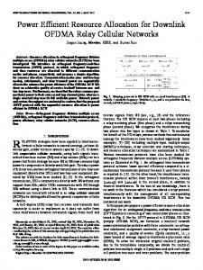
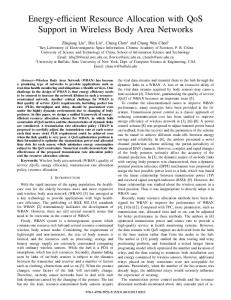
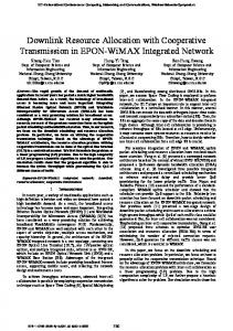
Argmax(A ) returns the index tuple [u, b, r] = [1, 3, 2] for 0 M AIN SIMULATION PARAMETERS OF A LGORITHM 1 . maximum value of A . The value at these indexes is preserved in A to mark an association between user u1 and RB r2 of BS Parameter Value b3 . Fig. 2 (c) shows the execution of steps 15 and 16 which correspond to the constraints C1 and C2. To satisfy constraint No. of BSs (B) variable C2, the column (RB) b3 r2 is marked with zeros for all users No. of RBs (R) variable except the user u1 . Similarly, to satisfy C1, the row u1 is No. of Users (U) variable Maximum transmit power per RB (Pt ) −42.60dBm/Hz marked with zero for all columns (RBs) except the ones that Background Noise power −168.60dBm/Hz belong to BS b3 . The row u1 is concatenated with the vector Λ, i.e., excluded from Argmax function in the next iteration. SINR Gap (Γ) 0dB Figs. 2 (d) to 2 (g) demonstrate the update of A matrix during Bandwidth 1MHz the remaining iterations of execution phase 2. At the end of Path loss model Rayleigh execution phase 2, the RBs b1 r2 , b2 r1 and b3 r2 have been Channel Estimation Perfect assigned to users u1 , u2 and u3 , respectively. The remaining RBs are assigned by execution phase 3 (steps 20 to 26) such of execution phase 4 (steps 28 and 29) is 3U BR. Therefore, that for each column (RB), the maximum entry is preserved the total number of flops required by the proposed algorithm to mark an association, whereas, the remaining entries are set to zero. This situation is demonstrated in Fig. 2 (h). Finally, are: Fig. 2 (i) shows the outputs of the algorithm computed by execution phase 4. No. of flops ≈ (4U BR + 1) + U BR(5B + 14) + 3U BR + U (2U BR + U + (B − 1)R) + BR(3U − 1) B. Performance Analysis ≈ O(U BR + U 2 + U B 2 R). Fig. 3 reports the sum rate versus the number of users (U ) From the above complexity analysis, we can conclude for a CRAN that consists of 2 BSs and 2 RBs per BS. The that the proposed interference aware greedy solution has a figure first reveals the increasing trend of sum rate with U . polynomial time complexity with respect to number of users, Moreover, the performance gap between the optimal schedulBSs, and RBs. In contrast, the computational complexity of ing using an exhaustive search (Algorithm II) and the proposed exhaustive search Algorithm II is O(2U BR ). heuristic (Algorithm I) is considerable for a large values of U , especially when U > Rt . This is due to the fact that for a large values of U , the interference becomes significantly IV. S IMULATION R ESULTS This section shows the performance of the proposed heuris- large. Therefore, the role of coordinated scheduling becomes tic algorithm for coordinated scheduling. The considered more pronounced as an interference mitigation technique. In CRAN downlink scenario is similar to Fig. 1 and the opti- addition, when U > Rt , some of the users remain unassigned mization is performed for sum rate (bits/sec) maximization to RBs which results in poor overall network utilization. Fig. 4 plots the sum rate versus the number of RBs per problem (3). In order to evaluate the performance of proposed BS for a CRAN that consists of 2 users and 2 BSs. Given algorithm from various aspects, the number of users, BSs, a constant value of U and B, the sum rate increases with R and RBs has been kept variable, whereas additional simulation as the total RBs, Rt = B.R available to the users increase parameters are summarized in Table II. The sum rate results which increases the chance of better network utilization. The reported in this section are the average results of Monte results demonstrate that the proposed heuristic covers the Carlo simulations. For a number of network configurations, search space (of size 2U BR ) well and performs close to the the sum rate of the proposed heuristic is also compared with the one obtained from optimal coordinated scheduling based optimal scheduling by exhaustive search. Fig. 5 quantifies the performance of the proposed heuristic on exhaustive search (Algorithm 2). solution for a considerably larger CRAN. The sum rate is plotted as a function of U in a CRAN consisting of 10 BSs A. An Illustration of Execution of Proposed Heuristic Algo- and variable RBs per BS ranging from R = 20 to 50. It is rithm observed that for a fixed value of U and B, the sum rate Fig. 2 shows an illustration of execution of the proposed increases with the increase in R. Moreover, given a fixed value heuristic algorithm (Algorithm 1) for coordinated scheduling. of B and R, the sum rate increases with U . The figure also A CRAN configuration consisting of three users, two BSs, shows that the proposed heuristic achieves a fairly large sum and two RBs per BS is considered for execution. Fig. 2 (a) rate, whereas, performing an exhaustive search for network of demonstrates the structure of A matrix such that the rows such complexity is clearly not feasible. represent the elements of set U, whereas the columns represent Fig. 6 shows the sum rate results as a function of U for the elements of set B × R. a CRAN consisting of variable number of BSs and 10 RBs Fig. 2 (b) demonstrates the steps 12 to 14 of first itera- per BS. For a given value of R and B, the result reveals that tion of execution phase 2. Initially, the vector Λ is empty, the sum rate increases with U . The result also shows that therefore, matrix A0 contains all elements of A. The function for a fixed value of U and R, the sum rate decreases with TABLE II
2169-3536 (c) 2016 IEEE. Translations and content mining are permitted for academic research only. Personal use is also permitted, but republication/redistribution requires IEEE permission. See http://www.ieee.org/publications_standards/publications/rights/index.html for more information.
This article has been accepted for publication in a future issue of this journal, but has not been fully edited. Content may change prior to final publication. Citation information: DOI 10.1109/ACCESS.2017.2663758, IEEE Access 7
B b2
b1 r2
r1
r2
b3
U u1
r1
r1
r2
u2 u3
0.05 3.01 3.13 0.02 2.95 3.98
0.22 0.04 0.49 0.01 4.61 5.47
2.50 3.05 1.98 0.26 2.68 4.04
B b2
b1 r2
r1
r2
b3
U u1
r1
r1
r2
u2 u3
0.05 3.01 3.13 0.02 2.95 3.98
0.22 0.04 0.49 0.01 4.61 5.47
2.50 3.05 1.98 0.26 2.68 4.04
B b2
b1 r2
r1
r2
b3
U u1
r1
r1
r2
u2 u3
0.05 3.01 3.13 0.02 2.95 0.00
0.00 0.00 0.00 0.00 4.61 5.47
2.50 3.05 1.98 0.26 2.68 0.00
Execution Phase 1: Steps 13,14 (c) Steps 14 to 16. RB b3 r2 is assigned to user u1 . To0)*7+72 satisfy C1 and 92 C2, allBRBs exceptRthose of !28%2 2*72 :*%2+7292
(a) Execution Phase 1 Step Matrix A10. for U Execution Phase 1: 9.1:Step 10. Execution Phase Step Execution Phase 1: Step 10.
= Execution (b) Execution Phase 11 to 13. = 1, Execution Phase 1:Steps Steps 11, Phase 1:2 Steps 11, 12x 12 0 0 3, B = 3, R = 2. The rows correspond to the initialy Λ is empty hence A = A. Argmax(A ) elements of U whereas, columns correspond to the returns indexes [u, b, r] = [1, 3, 2] for maximum b3 are marked zero for u1 and RB b3 r2 is marked zero for all users except u1 . Λ = {1}. elements of set B × R value of A i.e. 5.47
B b2
b1 r2 U r1 u1 0.00 0.00 u2 0.05 3.01 u3 2.50 3.05
r1
r2
r1
r2
0.00 0.00 4.61 5.47 3.13 0.02 2.95 0.00 1.98 0.26 2.68 0.00
B b2
b1
b3r
B b2
b1
br 3 r2
b3 r r2
r2 r1 r2 r1 r2 r1 r2 r1 U r1 U r1 u1 0.00 0.00 0.00 0.00 4.61 5.47 u1 0.00 0.00 0.00 0.00 4.61 5.47 u2 0.00 0.00 3.13 0.02 0.00 0.00 u2 0.00 0.00 3.13 0.02 0.00 0.00 u3 2.50Phase u3Execution Phase 1: Steps 13, 3.05 1: 0.00 0.26 2.68 0.00 2.50Phase 3.05 0.00 0.26 Execution 1: Steps 13,2.68 14 140.00 Execution Steps 15,16,11,12
Execution Phase 1: Steps 15,15, 16,16, 11,11, 12 12 Execution Phase 1:15, Steps Execution Phase 1: Steps 16, 11, 12 Execution Phase 13, 14 Execution Phase 1: Steps 15,16,11,12 Execution Steps 13, 14 (d) Steps 11 Phase to 13. x1:=Steps Λ 15, = {1} to 16.Phase RB1:b2Steps r1: 1 assigned to user u2 . (f) Steps 11 to 13. x = 3, Λ = {1, 2} therefore Execution 11, Execution 1: Steps 15,2,16, 11, 12 Execution Phase 1: Steps 15, 16,16, 11,therefore 1212 (e) Steps 14 0 Phase 0 C1!"#and C2, all RBs except those of b 2 A contains all elements of A except the elements To satisfySub'r' A contains all elements of A except the elements &#'($"#)%#&#*################## - ./#30"12:"# &#'($"#)%#&#*################## #$%# 0 0 for u1 (i.e. the 1st row). The argmax(A ) returns are marked zero for u2 and RB b2 r1 is marked for u1 and u2 (row 1 and 2). The argmax(A ) indexes [u, b, r] = [2, 2, 1] of maximum value of zero for all users except u2 . Λ = {1, 2}. returns indexes [u, b, r] = [3, 1, 2] for maximum A i.e. 3.13. value of A i.e.3.05.
b1 U u1
r1
r2
r r b3
B b2 r1
r2
r1
r2
0.00 0.00 0.00 0.00 4.61 5.47
Execution Phase 1: 1: Steps 13,14 Phase Steps 13,14 Execution Phase 1: Steps 13,14 u2 Execution 0.00 0.00 3.13 0.02 0.00 0.00 Execution Phase 1: Steps 13,14 Execution Phase 1: Steps 13,14 Execution Phase 1: Steps 13,14 u 3
2.50 3.05 0.00 0.00 0.00 0.00
b1 r2
r
B b2 r1
r2
b3r
U u1
r1
r1
r2
u2
0.00 0.00 3.13 0.02 0.00 0.00
u3
2.50 3.05 0.00 0.00 0.00 0.00
0.00 0.00 0.00 0.00 4.61 5.47
b1 U u1
r1
r2
r b3r
B b2 r1
r2
r1
r2
0 0 0 0 1 1 u2Execution 0 Phase 0 1 Steps 1 27,28 0 0 3: Phase 3: Steps 27,28 u3Execution 1 1 0 0 0 0
Execution Execution Phase Phase 1: Steps 1: Steps 13,14 Execution Phase 1:13,14 13,14 (g) Steps 14 to 16. The RB bSteps 1 r2 is assigned to u3 . To Sub'r' satisfy C2 all '$"#(%#&# RBs except those !"# C1 and&# #$%#
Execution Phase 3: Steps (h) Execution Phase 3: The remaining RBs are (i) Execution Phase 4: Steps 27, 28. 27,28 ˆ matrix, Total network utilization a = 18.78 assigned by Steps 19 to 25. The RB b1 r1 (1st A of b1 are marked zero for u3 and the RB b1 r2 Column) has a maximum value at row u3 hence is marked zero for all users except u3 . Execution it is assigned to user u3 . In a similar manner, the phase 2 terminates here. All three users have been RBs b2 r2 and b3 r1 are assigned to users u2 and assigned at least one RB u1 respectively. Fig. 2. An Illustrative example showing the execution of Algorithm 1 for a CRAN consisting of U = 3, B = 3 and R = 2
increase in the number of BSs B. This phenomenon is due to the fact that the total interference seen by the observer u (the denominator term of (2)) increases with B. Since, a user can be only assigned to a single BS at a time (constraint C1), hence, the total network utilization decreases. V. C ONCLUSIONS This work considered the coordinated scheduling problem in the downlink of CRAN. The user-to-BS assignment problem is modeled as a combinatorial optimization problem. The objective is to maximize a generic network utility expressed as sum rate (bits/sec) under the practical constraint, i.e., a user cannot be served by more than one BS; however, it can be assigned to multiple RBs within the transmit frame of each BS. Moreover, a RB can be assigned to only one user at a time. An optimal solution of such an optimization problem can be found
by performing an exhaustive search over all possible user to BS assignments that satisfy the above mentioned constraints. However, exhaustive search complexity is exponential to the product of number of users, BSs, and RBs per base station. To solve the coordinated scheduling problem in linear time, this work proposed a low complexity heuristic. The sum rate of the proposed algorithm is compared with the optimal scheduling using exhaustive search. Simulation results are reported for a number of CRAN scenarios and suggest that the proposed heuristic algorithm performs near to optimal scheduling.
R EFERENCES [1] J. G. Andrews, S. Buzzi, W. Choi, S. V. Hanly, A. Lozano, A. C. K. Soong, and J. C. Zhang, “What will 5G be?” IEEE Journal on Selected Areas in Communications, vol. 32, no. 6, pp. 1065–1082, June 2014.
2169-3536 (c) 2016 IEEE. Translations and content mining are permitted for academic research only. Personal use is also permitted, but republication/redistribution requires IEEE permission. See http://www.ieee.org/publications_standards/publications/rights/index.html for more information.
This article has been accepted for publication in a future issue of this journal, but has not been fully edited. Content may change prior to final publication. Citation information: DOI 10.1109/ACCESS.2017.2663758, IEEE Access 8
10 9
Optimal Brute Force algorithm Proposed Heuristic
Sum Rate (bits/Hz)
Sum rate (bits/sec)
10 8
10 7
10 6
2
3
4
B=10,R=20 B=10,R=30 B=10,R=40 B=10,R=50
10 8
10 7
5
20
40
60
80
No. of Users (U)
120
140
160
180
200
Users
Fig. 3. Sum Rate (bits/sec) versus the number of users (U). The number of BSs (B) is 2 and number of RBs per BS (R) is 2.
10 8
100
Fig. 5. Sum rate (bits/sec) versus the number of users (U). The number of BSs (B) is 10 and the number of RBs (R) is variable from R=20 to 50.
×10 7 Optimal Brute Force algorithm Proposed Heuristic
9 8 7
R=10,B=15 R=10,B=20 R=10,B=25 R=10,B=30
10
Sum Rate (bits/sec)
Sum rate (bits/sec)
6
7
5 4
3
2
10 6
2
3
4
10
5
20
30
40
50
60
70
80
90
100
No. of Users (U)
No. of RBs per BS (R)
Fig. 4. Sum rate (bits/sec) versus the number of RBs (R). The number of BSs (B) is 2 and the number of users (U) is 2.
Fig. 6. Sum rate (bits/sec) versus the number of users (U). The number of RBs (R) is 10 and the number of BSs (B) is variable from B=15 to 30.
[2] X. Ge, H. Cheng, M. Guizani, and T. Han, “5G wireless backhaul networks: challenges and research advances,” IEEE Network, vol. 28, no. 6, pp. 6–11, Nov.-Dec. 2014. [3] R. Wang, H. Hu, and X. Yang, “Potentials and challenges of C-RAN supporting multi-RATs toward 5G mobile networks,” IEEE Access, vol. 2, pp. 1187–1195, 2014. [4] “Coordinated multi-point operation for LTE physical layer aspects,” 3rd Generation Partner Project, Tech. Rep. Release 11.1.0, 2011. [5] Q. Wang, D. Jiang, G. Liu, and Z. Yan, “Coordinated multiple points transmission for LTE-Advanced systems,” in 2009 5th International Conference on Wireless Communications, Networking and Mobile Computing, Sept 2009, pp. 1–4. [6] “C-RAN: the road towards green RAN,” White Paper V.2.5, China Mobile Research Lab, pp. 15–16, 2011. [7] H. Z. J. Wu, S. Rangan, Green Communication. CRC Press,Boca Raton, Fl - USA, 2013. [8] S. H. Park, O. Simeone, O. Sahin, and S. Shamai, “Joint precoding and multivariate backhaul compression for the downlink of cloud radio access networks,” IEEE Transactions on Signal Processing, vol. 61, no. 22, pp. 5646–5658, Nov 2013. [9] B. Dai and W. Yu, “Sparse beamforming for limited-backhaul network mimo system via reweighted power minimization,” in 2013 IEEE Global Communications Conference (GLOBECOM), Dec 2013, pp. 1962–1967. [10] Y. Shi, J. Zhang, and K. B. Letaief, “Group sparse beamforming
for green cloud-ran,” IEEE Transactions on Wireless Communications, vol. 13, no. 5, pp. 2809–2823, May 2014. W. Yu, T. Kwon, and C. Shin, “Multicell coordination via joint scheduling, beamforming and power spectrum adaptation,” in INFOCOM, 2011 Proceedings IEEE, April 2011, pp. 2570–2578. H. Dahrouj, W. Yu, T. Tang, J. Chow, and R. Selea, “Coordinated scheduling for wireless backhaul networks with soft frequency reuse,” in 21st European Signal Processing Conference (EUSIPCO 2013), Sept 2013, pp. 1–5. P.R.J. Ostergrd, “The auction algorithm: A distributed relaxation method for the assignment problem,” Annals of Operations Research, vol. 14, pp. 105–123, 1988. M. Y. Lyazidi, N. Aitsaadi, and R. Langar, “Dynamic resource allocation for Cloud-RAN in LTE with real-time BBU/RRH assignment,” in 2016 IEEE International Conference on Communications (ICC), May 2016, pp. 1–6. P. Y. L. Feng, W. Li and X. Qiu, “An enhanced OFDM resource allocation algorithm in C-RAN based 5G public safety network,” Hindawi Journal on Mobile Information Systems, 2016. S. G. V. A. e. a. Nardini, G., “Practical large-scale coordinated scheduling in LTE-advanced networks,” Wireless Networks, vol. 22, no. 1, pp. 11–31, 2016. [Online]. Available: http://dx.doi.org/10.1007/s11276-015-0948-6 K. Wang, K. Yang, X. Wang, and C. S. Magurawalage, “Cost-effective
[11]
[12]
[13]
[14]
[15]
[16]
[17]
2169-3536 (c) 2016 IEEE. Translations and content mining are permitted for academic research only. Personal use is also permitted, but republication/redistribution requires IEEE permission. See http://www.ieee.org/publications_standards/publications/rights/index.html for more information.
This article has been accepted for publication in a future issue of this journal, but has not been fully edited. Content may change prior to final publication. Citation information: DOI 10.1109/ACCESS.2017.2663758, IEEE Access 9
[18]
[19] [20]
[21]
resource allocation in c-ran with mobile cloud,” in 2016 IEEE International Conference on Communications (ICC), May 2016, pp. 1–6. S. Geirhofer, A. Barbieri, N. Bhushan, and P. Gaal, “Capacity enhancement through opportunistic activation of relays in cloud ran deployments,” in 2013 IEEE Globecom Workshops (GC Wkshps), Dec 2013, pp. 1–6. A. Abdelnasser and E. Hossain, “Resource allocation for an ofdma cloud-ran of small cells underlaying a macrocell,” IEEE Transactions on Mobile Computing, vol. 15, no. 11, pp. 2837–2850, Nov 2016. A. Douik, H. Dahrouj, T. Y. Al-Naffouri, and M. S. Alouini, “Coordinated scheduling for the downlink of cloud radio-access networks,” in 2015 IEEE International Conference on Communications (ICC), June 2015, pp. 2906–2911. G. Golub and C. V. Loan, Matrix Computations. The John Hopkins University Press, Baltimore M.D USA, 1983.
2169-3536 (c) 2016 IEEE. Translations and content mining are permitted for academic research only. Personal use is also permitted, but republication/redistribution requires IEEE permission. See http://www.ieee.org/publications_standards/publications/rights/index.html for more information.