Efficient Lookahead Routing and Header Compression for. Multicasting in Networks-On-Chip. Lei Wang. Poornachandran Kumar. Rahul Boyapati. Ki Hwan Yum.
Efficient Lookahead Routing and Header Compression for Multicasting in Networks-On-Chip Lei Wang
Poornachandran Kumar Rahul Boyapati Ki Hwan Yum Eun Jung Kim Department of Computer Science and Engineering Texas A&M University College Station, TX 77840 {wanglei, poorna, rahul, yum, ejkim}@cse.tamu.edu
ABSTRACT As technology advanced, Chip Multi-processor (CMP) architectures have emerged as a viable solution for designing processors. Networks-on-Chip (NOCs) provide a scalable communication method for CMP architectures as the number of cores is increasing. Although there has been significant research on NOC designs for unicast traffic, the research on the multicast router design is still in infancy stage. Considering that one-to-many (multicast) and one-to-all (broadcast) traffic are more common in CMP applications, it is important to design a router providing efficient multicasting. In this paper, we propose an efficient lookahead routing with limited area overhead for a recently proposed multicast routing algorithm, Recursive Partitioning Multicast (RPM) [17]. Also, we present a novel compression scheme for a multicast packet header that becomes a big overhead in large networks. Comprehensive simulation results show that with our route computation logic design, providing lookahead routing in the multicast router only costs less than 20% area overhead and this percentage keeps decreasing with larger network sizes. Compared with the basic lookahead routing design, our design can save area by over 50%. With header compression and lookahead multicast routing, the network performance is improved by 22% in a (16 × 16) network on average.
Categories and Subject Descriptors C.1.2 [Computer Systems Organization]: MultiprocessorsInterconnection architectures; C.1.4 [Parallel Architectures]: Distributed architectures
General Terms Design, Performance
1. INTRODUCTION With the growing number of cores, providing efficient communication in a single die is becoming critical for CMPs and
Permission to make digital or hard copies of all or part of this work for personal or classroom use is granted without fee provided that copies are not made or distributed for profit or commercial advantage and that copies bear this notice and the full citation on the first page. To copy otherwise, or republish, to post on servers or to redistribute to lists, requires prior specific permission and/or a fee. ANCS’10, October 25-26, 2010, La Jolla, CA, USA. Copyright (c) 2010 ACM 978-1-4503-0379-8/10/10. . . $10.00.
System-on-Chips (SoCs) [2] [12]. Traditional interconnects such as shared buses and dedicated wires do not give a scalable solution, but increase the complexity of chip designs. Networks-on-chip (NOCs) have been widely accepted as a promising architecture to orchestrate chip-wide communication in CMPs such as Intel Teraflop 80-core [8], Tilera 64-core [18], RAW [15] and TRIPS [7]. As the number of processing cores is increasing, the size of the NOC is also increasing to provide connectivity to all processor cores. Thus, it is inevitable to suffer from high communication latency in the near future. To overcome high communication latency, it is urgent to design a low latency router within a limited area budget and power constraint. There have been a handful of studies on low-latency router designs using speculation, pre-computation, or aggressive flow control. However, in all previous work, NOCs have been designed for unicast traffic, which are very inefficient at handling multicast and broadcast traffic. Various CMP applications and programming models require one-to-many communication such as broadcast and multicast in NOCs. In cache-coherent shared memory systems with a large number of cores, it is essential to provide efficient multicasting to maximize performance. It is known that cache coherence protocols heavily rely on multicast or broadcast communication characteristics to maintain ordering amongst requests [13] or to invalidate shared data spread on different caches using directory. Recent work on multicast routing in NOCs are Virtual Circuit Tree Multicasting (VCTM) [9], bLBDR [14] and RPM [17]. VCTM [9] proposes an efficient multicast and broadcast mechanism. Before sending multicast packets, VCTM needs to send a setup packet to build a tree. VCTM requires extra storage to maintain the tree information for multicast. bLBDR [14] enables the concept of virtualization at the NOC level and isolates the traffic into different domains. Multicasting in bLBDR is based on broadcasting in a small domain. RPM [17], recently proposed multicast routing algorithm, is scalable and deadlock free. It provides multicast routing based on recursive partitioning of the whole network. In a 2-D mesh topology the whole network is divided into eight parts according to the position of the current node.(Some parts can be empty if the current node stays in the network edge.) When a multicast packet is generated, according to the distribution of destination nodes in the eight parts, the source router will decide how many copies it needs and in which
direction each replica should be sent. After each replica arrives at the next hop, that node becomes a new source and will partition the network based on its position. This partitioning procedure occurs recursively until all the destination nodes receive a copy of that packet. Compared with VCTM and bLBDR, RPM is more bandwidth-efficient and scalable. However, it is challenging to design a low latency router supporting RPM due to the complexity of routing computation logic and the overhead of a big packet header. In a wormhole-switched network, the router latency plays a dominant role in the packet latency. Reducing the router latency with less pipeline stages is critical to improve packet latency. Lookahead routing [5] in unicast is used to remove route computation from the critical path by calculating packets’ routes one hop ahead of the current router. However, providing lookahead routing for RPM is not easy since some intermediate routers need to make replicas for one packet, which means a router can have more than one downstream router. How to efficiently calculate routing information for multiple downstream routers is an open problem. Another problem in RPM is the overhead of the packet header. The packet header normally carries the whole destination list. RPM uses bit string encoding to implement the destination list. However, as the network size grows, the number of bits will increase. Taking a (16×16) mesh network for example, we need to define a 256-bit header. Considering that the link width is 128 bits and the flit size is the same as the link width, we need two flits to carry the destination list. It takes two cycles for the downstream router to receive the whole header, which means routing calculation cannot be done in one cycle. It is equivalent to increasing the number of router pipeline stages which eventually degrades the network performance. Motivated by these problems of RPM, we propose an efficient lookahead routing design and introduce a novel compression scheme. Our route computation logic can support lookahead routing with limited area and power overhead. The proposed compression scheme can highly reduce the overhead of a head flit in multicast traffic. Our compression stage can be overlapped with lookahead routing stage, which means the compression stage will not be in the critical path and have no effect on router latency. Our main contributions are summarized as follows: • We explore the detailed design of a multicast router, especially how to provide lookahead routing with a recent multicast routing algorithm. • We analyze the overhead of a multicast header and propose a compression scheme. As far as we know, this is the first work to introduce header compression into the NOC router design. • We evaluate our multicast router design using the most recent multicast routing algorithm by varying the traffic patterns and network sizes. • Detailed simulation results show that with our route computation logic design, providing lookahead routing in a multicast router only costs less than 20% area
overhead and this percentage keeps decreasing with larger network sizes. Compared with the basic lookahead routing design, our design can save over 50% area. With header compression and lookahead multicast routing, the network performance can be improved by over 22% in a large network. The rest of this paper is organized as follows. We briefly present the unicast, multicast router architecture and RPM routing in Section 2. We propose the multicast lookahead routing design in Section 3. The header compression scheme is discussed in Section 4. In Section 5, we describe evaluation methodology and summarize the simulation results. Finally, we draw conclusions in Section 6.
2.
BACKGROUND
In this section, we present a unicast router architecture and its pipeline stages. Then we briefly describe a recently proposed multicast routing algorithm, Recursive Partitioning Mulitcast (RPM).
2.1
Unicast Pipelined Router Architecture
Figure 1 shows a virtual channel (VC) unicast router architecture used in NOCs [4]. The main building blocks are input buffer, route computation logic, VC allocator, switch allocator, and crossbar. To achieve high performance, unicast routers process packets with four pipeline stages, which are routing computation (RC), VC allocation (VA), switch allocation (SA), and switch traversal (ST). First, the RC stage directs a packet to a proper output port of the router. Next, the VA stage allocates one available VC of the downstream router determined by RC. The SA stage arbitrates input and output ports of the crossbar, and then successfully granted flits traverse the crossbar in the ST stage. Considering that only the head flit needs to do routing computation and middle flits always have to stall at RC stage, recent router designs use techniques such as lookahead routing [5] to reduce the number of pipeline stages. The functionality of lookahead routing is the same as normal RC stage, which is to calculate the output ports for packets. However, instead of calculating routing information for the current router, lookahead routing does calculation for the next hop and stores the routing information in the head flit. For the current router, routing information is already obtained in the upstream router. The RC stage and VA stage can be overlapped, since the VC allocator does not need to wait for the output of RC logic. In this way, lookahead routing removes route computation from the critical path. Recent work [6] [11] uses lookahead signals or advanced bundles to implement lookahead routing for unicast routers.
2.2
Multicast Router Architecture
Multicast (one to many) and broadcast (one to all) refer to the traffic patterns in which the same message is sent from one source node to a set of destination nodes. Compared with the unicast router design, the multicast router has its own characteristics. In multicast traffic, a packet that has multiple destinations needs to be replicated to several copies in intermediate routers. To support a multicast function, routers need a replication component. To avoid the storage overhead for replica management, normally replications take place at the ST stage, and the basic unit is a flit rather than
Route Computation
Input 0
VC Allocator Switch Allocator
VC 1
Output 0
VC 2
. .
.
VC n Input buffers
.
.
. VC 1
Input 4
Output 4
VC 2 VC n Input buffers
Crossbar switch
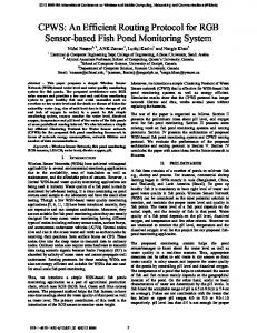
Figure 1: Unicast Pipelined Router Architecture.
network, where the source is 9 and its six destinations are 0, 1, 2, 3, 12 and 14. The RPM partition logic will divide the network according to the source Node 9. Destinations 2 and 3 lie in Part 0, destination 1 lies in Part 1, destination 0 lies in Part 2, destination 12 lies in Part 4 and destination 14 lies in Part 6. According to the RPM routing rules, current Node 9 needs to make two replicas, one for North and the other for South. To avoid redundant replication destinations 0, 1, 2 and 3 only stay in the North packet header while destinations 12 and 14 only stay in the South packet header. When the North replica arrives at Node 5 and the south replica gets to Node 13, Node 5 and Node 13 becomes the new source nodes and will go through the same procedure Node 9 does. This procedure recursively occurs until all the destinations receive one copy of the original data. 7
a packet. RC stage in multicast is not only just to calculate the output directions but to decide how many replications the current router should make. At the VA stage, virtual channel allocator should consider multiple requests from the same packets which may traverse to different output ports at the same time. The same situation will occur at the SA stage. Here, we can see that the key point in multicast router design is the RC logic.
2
The core idea of RPM is that the routing decision is made based on the current network partitioning. The definition of a current router is the router which receives one copy of the original multicast packet even though it is not one of the destinations. The current router divides the whole network into at most eight parts according to its position. Destination nodes in a multicast packet belong to one of these parts. In the general case, if the source node is in the center of the network, all the eight parts have at least one node. However, if the source node is located in the corner or edge of the network, some parts may be empty. Taking a (4×4) mesh network as an example, partitioning is defined as in Figure 2. The network is recursively partitioned according to the position of the current router until all the destinations get the packet. Special rules are provided to avoid redundant replication of packets in each intermediate router. Virtual networks (VN), which separate a physical network into multiple networks, are introduced to make RPM a deadlock-free algorithm. Figure 3 shows a multicast traffic example in a (4 × 4) mesh
Source node
0
N 5
3
6
7
4
5
W
E
6 Three Parts (5, 6, 7)
Eight Parts
S
3 0
2.3 RPM Routing Recently Wang et. al [17] proposed a deadlock free multicast routing algorithm for NOCs, Recursive Partitioning Multicast (RPM). Unlike previous work VCTM [9], RPM does not maintain any lookup table for multicast in each router. RPM directly sends out multicast packets without sending a unicast+setup packet to each destination first. In other words, RPM does not need to build a tree structure in each intermediate router before sending the real multicast data packet. However, in each multicast packet header or head flit, RPM needs one field to indicate all the destination nodes’ positions. This overhead of the head flit can be one drawback of RPM which makes it hard to scale to large networks. Detailed discussion about head flits will be in Section 4.
1
4
1
5
2
7
1
3
Three Parts (0, 1, 7)
Three Parts (3, 4, 5)
Three Parts (1, 2, 3)
Figure 2: Network Partitioning Based on Source Node Positions. Normally the whole network will be divided into 8 parts. However, for the nodes located in the corner or edge, some parts are empty. Source North Header
Destination 0
1
4
5
2
3
6
7
10
11
14
15
1111000000000000 Continuous zeros South Header
North
8
9 South
0000000000001010 12
13
Continuous zeros
Figure 3: Packet Header Patterns in a Multicast Traffic. After making two replicas (North and South), there are a lot of zeros in each packet header which can be potentially compressed.
3.
MULTICAST LOOKAHEAD ROUTER DESIGN
In unicast traffic, the packet at the head of each VC needs to use the route computation logic and proceed to one output port. It means that, for each packet, the current router only has one downstream router. To support lookahead routing in unicast, each router can have one route computation logic for each input port or each VC. However, in multicast
traffic, one packet may go to several output ports in an intermediate router, if this packet needs to be replicated in this router. Then, for this packet, the current router will have more than one downstream router. To provide multicast lookahead routing, each input port or VC should have more than one route computation logic in order to not increase the latency of the RC stage, or else routers should get all the next hop route information in multiple cycles without adding any logic. Taking a 2D Mesh topology as an example, each router has at most four neighboring routers. In the worst case, to support multicast lookahead routing, each router should have three 1 route computation logic blocks to calculate route information for all the downstream routers in one single cycle. Without adding more RC logic blocks, performing lookahead routing for multicast will take more than one cycle. Then the benefit of lookahead routing will be lost. ����������� ��� ������ � � � � � � � � � � � �
����������� ����
��� �
network parts for the two next-hop routers are represented by the solid and the dashed lines. It can be clearly seen that there are a lot of sharing parts between the parts of the two next-hop routers. The overlapping portions are depicted with the routers in gray. Hence, there exists a lot of redundancy in the partition logic if three RPM logics are implemented separately for the three next-hop routers. The new partitioning scheme is illustrated in Figure 6. Instead of directly dividing the network into 8 parts, the network is first divided into 24 parts, and the eight-part signals for each of the three next-hop routers are computed from these 24 parts signals. The 24 parts comprise of 8 immediate surrounding neighbor routers and 16 parts that may contain more than one router. The part signals for each of the 24 parts are generated by OR-ing the destination bits in the header. The eight part signals for each of the nexthop routers are computed using the 24 part signals. Table 1 shows how the Part 0-7 signals are calculated for the two next-hop routers (Node 1 and Node 7) in Figure 6. +)((",$ (&)$"(
!"#$ %&' (&)$"(*
��� � ��� � ��� � ��� � ��� ���
��� �
Figure 4: A Partitioning Logic for RPM. The partitioning logic is simply implemented using OR gates with inputs from the destination list. Each router has its own logic based on its position in the network. By analyzing the RPM routing logic design, we find that multicast lookahead routing can be efficiently supported by redesigning its partitioning logic. The RPM partition logic occupies an area that scales linearly with the network size. In a (n × n) network, the RPM partition logic block consumes an area of the order of n2 times the area of an OR gate. An example of a partition logic is shown in Figure 4. It is implemented for Router 9 in a (4 × 4) network as shown in Figure 10. The destination bits of a multicast packet generate part signals for eight parts using OR gates. Although there are four next-hop routers, their partitions have a considerable overlap. This overlap can be exploited to remove redundant logics to avoid providing three RPM routing logic, and finally reduce the area. Considering a (8×8) network in Figure 5, the current router and two next-hop routers are marked in the figure. The eight 1 We assume minimal routing. Packets cannot be routed back.
-&)$"( ., $%" &/"(01''.,2 '1($.$.&, 1("1*
31($.$.&, 4&),51(6 7&( 31($.$.&, 4&),51(6 7&(
Figure 5: Basic Network Partitioning for Two NextHop Routers. The grey nodes are the overlapping portions of the two partitioning. From Table 1, it can be observed that P0 is used to compute the Part 0 signal for both the North and the East next-hop routers. Similarly, P3 and P4 are used to compute Part 2 signal. In this way, we can reuse the common logic and avert redundancy. The area can be roughly obtained from the number of OR gates utilized to generate the part signals. The number of OR gates required for n bits representing n routers is n − 1. Therefore, each part which contains a × b routers needs ab − 1 OR gates to generate the part signals. The original 8 partition scheme for a (n×n) network is shown in Figure 7. The number of OR gates can be calculated for each of the 8 parts and then summed up to find the total number of gates for each RPM RC logic. The total number of OR gates can be found to be n2 − 9 for a (n × n) network. For lookahead routing without area optimization, the number of gates is three times that of a single logic which is 3n2 − 27. The partitioning scheme for a (n × n) network with area optimization is shown in Figure 8. The number of OR gates to generate the 24 part signals can be found to be n2 − 25. The 8 part signals for the next hop routers can be generated as described in Table 1. The number of OR
E?; I B@??9C;D ?=@;9? DE?; H
DE?; J
DE?; G 89:; ?=@;9?A
DE?; K
8=P9 H 8=P9 G 8=P9 F
DE?; L
8=P9 M 8=P9 I 8=P9 J 8=P9 K 8=P9 L
DE?; M
DE?; F
Table 1: Calculation of the 8 Parts Signals from the Newly Defined 24 Parts. (N: Node, P: Part, OR: or gate.)
DE?; GK DE?; GJ
Part Num
DE?; GI
0 1
DE?; N
DE?; O
DE?; GF DE?; GG
Y=@;9? QC ;>QC\ >E?;Q;Q=C E?9EA
DE?; GH
2
3
P DE?;Q;Q=C R=@C E?S T=? C9U AV;QWQXE;Q=C
4 Figure 6: A New Network Partitioning Scheme, which divides the network into 24 parts instead of 8 parts.
5 6
7
4. ij b
i j lmnkn bo
]^_` c
]^_` b
]^_` a
bj k
b j lmnkn bo
]^_` d
]^_` h
lmn in bo j k ]^_` e
lmn in bo j b ]^_` f
lmn in bo j lmnkn bo ]^_` g
pq__rm` _s q`r_
Figure 7: Logic.
Gates Calculation with Original RPM
Detailed area and power analysis of our new RC logic design are in Section 5. 2 3
n2 − 25 + 45 n2 + 20 − (n2 − 9)
N E N E
gates needed to compute the eight part signals for the three next-hop routers can be counted to be 45 (3 × 15). This is a constant even the network size increases. The total number of gates for lookahead routing with area optimization is n2 + 202 . Therefore, the extra area overhead of lookahead routing is reduced from 2n2 − 18 to 293 gates with the help of the area optimization technique.
ij k
Direction of next hop N E N E N E
N E N E N E
Computation logic
P0 OR P1 P0 OR P15 P2 N0 OR P1 P3 OR P4 N1 OR N2 OR P2 OR P3 OR P4 OR P5 N2 OR P5 N3 OR P6 N3 OR N4 OR P6 OR P7 OR P8 OR P9 N4 OR N5 OR P7 OR P8 OR P9 OR P10 N5 OR P10 N6 OR P11 N6 OR N7 OR P11 OR P12 OR P13 OR P14 P12 OR P13 N0 OR P15 P14
HEADER COMPRESSION
In RPM routing, normally the packet header carries the whole destination list. When the network size becomes large, such as (16×16), the overhead of the header becomes so critical that the downstream router may not receive the whole destination list in one cycle. Let’s go back to the previous multicast example in Figure 3. Since we have totally 16 nodes in a (4×4) mesh network, using bit string encoding needs 16 bits to carry the destination list in the worst case. However, when we analyze this traffic in detail, we can find some interesting points in this destination list bit encoding. First, in Node 9, the packet will be replicated into two copies, one for North and the other for South. According to RPM [17], to avoid redundant replication, the North packet header only carries destinations 0, 1, 2 and 3, while the South packet carries only destinations 12 and 14. In these two packet headers, at least half of the bits are zeros since North packet header will never carry destinations below the source row and South packet will never carry destinations above the source row. Hence, there are twelve continuous zeros in North packet, and fourteen zeros in South packet among which twelve are continuous zeros. Second, when a multicast packet traverses in the network, each time it arrives at one destination, the bit for that position will become zero, which means as time elapses, the number of zeros in the header increases. Instead of transmitting all these redundant zeros, the packet header can be compressed. There has been plenty of work done in data compression, such as frequent value based compression [19], significance based compression [3] and frequent pattern compression [1]. Frequent value based compression
tuvw |
tuvw {
tuvw z
tuvw y
y
y
y
{
yy
y
y y
x
} yy
yy
~ yy
y{ tuvw y} tuvw y| y{
y tuvw }
yy
z
y tuvw ~
y y
{
| y y
y tuvw { tuvw
{y {y {y tuvw tuvw yx tuvw yy
bits corresponding to these destinations are always set to 0 in the header. Therefore, the bits in the header for these destinations are removed as depicted in Figure 9(b). According to the policy of avoiding redundant packet replications in RPM, each direction can at most have destinations in three parts, which means using three bits for parts information in the header is always enough. The destination bits for the three parts follow row-wise ordering. The part signals Pi Pj and Pk are set to 1 if at least one destination exists in their parts respectively. Any part signal being zero indicates that no destination exists in that part, which means that all the destination bits in that part are set to zero, since we store all the destination bits of a part continuously.
tuvw x
tuvw y{ y{ {{ tuvw yz
ÀÁÂÃ ÄÇ
ÀÁÂÃ ÄÆ
ª
«
¬
²
®
¯
°
³
±
¨©
««
«¬
«
«²
«®
vv
w w
v
Figure 8: Gates Calculation of Lookahead Routing Logic after Logic Reuse.
is based on temporal locality of values when accessing memory and hence they can be compressed while transmitting or storing. Significance based compression is built on the fact that most of the significant bits have redundant information and an index can be transmitted along with lower order bits instead of the whole word. In frequent pattern compression, each 32-bit word is encoded as a 3-bit prefix plus data if it matches a pattern in a table that has a list of patterns selected based upon their high frequency in the commercial and integer benchmarks. But, considering the feature of recursive partitioning at each node in RPM, we propose a new compression scheme which can efficiently reduce the overhead of a packet header.
£
¥¦ ¤ ¡¢
§¦ ¤
¡¢
¡¢
Figure 9: RPM Header Format and Proposed Header Compression Format. The original packet header format of RPM is shown in Figure 9(a), while a new format is shown in Figure 9(b). The original header contains destinations in serial order from 0 to n-1. The new header format is implemented to exploit the features provided by RPM partition logic. It includes a compression bit to indicate if the header is compressed or not. The compression bit is followed by three relevant part signal bits Pi , Pj and Pk which are obtained from the RPM partition logic. Other bits following these part signal bits represent the destinations that belong to the corresponding parts i, j and k. Part i, j and k are selected based on the direction in which the packet will be sent. For instance, if the packet is sent eastward, the parts i, j and k are respectively 0, 6 and 7 of the current router. Destinations in the other parts will not receive this east direction packet. Hence the
ÀÁÂÃ ÄÈ
ÀÁÂÃ ÄÉ
ÀÁÂÃ ÄÅ
ÀÁÂà ÄÊ ´µ¶·¸¹
ÀÁÂÃ ÄÌ
ÀÁÂà ÄË º¹»¼½¾¿¼½µ¾
Figure 10: In a (4×4) network, Node 9 sends a multicast packet and Node 10 is the only destination. The whole network is divided into eight parts according to the position of Node 9. Í
Î
Ï
Ð
Ñ
Ò
Ó
Ô
Õ
Ö
ÎÍ ÎÎ ÎÏ ÎÐ ÎÑ ÎÒ
ÜÝÞ
Í
Î
Ï
Ð
Ñ
Ò
Ó
Ô
Õ
Ö
ÎÍ ÎÎ ÎÏ ÎÐ ÎÑ ÎÒ
Í
Î
Ï
Ð
ÜßÞ
Ú
ÜàÞ
Î Í
Ñ
Ò
×Ù ×Ø ×Û Ï Ð Ó Í Î Ï Ð Ñ Ò
Ú
Í
Î
Î
Ó
Ô Ô
Õ
Ö
ÎÍ ÎÎ
ÎÑ ÎÒ ÎÍ ÎÎ
Í
×Ù ×Ø × ÎÍ ÎÎ Û
Figure 11: Comparison of Different Headers. (a) RPM format, (b) Proposed Header Compression format and (c) the compressed header for the example in Figure 10. An example of this compressed packet header in a (4×4) network is shown in Figure 10. It shows the current router and the direction in which the packet is traveling. The original packet header and new packet header formats are illustrated in Figure 11(a) and (b). 16 routers requires 16 bits in the original header format. The size of the new header varies depending on the position of the current router and the destination list. In this example Router 9 sends a packet to Router 10. Parts i, j, k are 0, 6 and 7 respectively. The destination bits are Router 2,3,6,7 for part 0, Routers 14, 15 for part 6 and Routers 10, 11 for part 7. Since the destination is only 10, P0 and P6 are 0 while P7 is 1. The destination bits for P0 (2,3,6,7) and P6 (14,15) are omitted, because the
á â ã ä
part bit P0 set to 0 already carries the information that the destination bits for routers 2, 3, 6 and 7 are zeros, and similarly for P6. The final header after compression is shown in Figure 11(c). The first bit for compression is set to 1 which means that this header is compressed. The second, third and fourth bits are the part signals for parts 0, 6 and 7 which are 0, 0 and 1 respectively. The destination bits for part 7 whose part signal is 1 are set to 1 and 0 for Router 10 and 11 respectively. It can be observed that the number of bits were reduced from 16 to just 6 in this case. The 6 bits include a compression overhead of 4 bits and just 2 bits for sending the actual destination bits. The compression overhead of 4 bits is a constant and will not increase with the size of the network. Furthermore, the partition logic can be used to implement the compression eliminating the need for a new compression logic. Since partitioning in RPM is based on the position of the current router, routers at different positions will decode the same header in different ways. This also depends upon the traversal direction of packets. However, the header decoding for a particular router in a dedicated direction is fixed and can be implemented by synthesized hardware logic for each router. Also, the size of a compressed header can vary from packets to packets depending on whether each of the part signals is set to 0 or 1. For instance, in Figure 10, if Routers 6 and 7 are packet destinations, then Part 0 would be set to 1 by the RPM partition logic and hence the destination bits 2, 3, 6 and 7 would be included in the header. Therefore, the location of the bits for destination node 10 and 11 in the header should be changed. In this way, decoding logic of the packet header needs multiplexing among the different possible locations for each destination bit and using Pi , Pj and Pk as the selection bits. Figure 12 shows the hardware of the decompression stage in Router 10 in a (4 × 4) network for a packet sent from Router 9. The decompression logic needs to decode the destination bits from the header and forward it to the RPM logic for route computation. The destination bits for Router 2, 3, 6 and 7 are located at the bit number 4, 5, 6 and 7 if the P0 is 1, otherwise they will not present in the header. These four destination bits can be extracted from the header with four multiplexers. The destination bits 14 and 15 can be located if P6 is set to 1) at bit number 8, 9 or 4, 5 depending on whether P0 is set to 1 or 0 respectively. Hence, the extraction of these destination bits need an extra stage of multiplexing. Similarly, the destination bits of Router 10 and 11 can have four different locations and can be multiplexed using the combination of P0 and P6 as the selection signals. In a similar mode, the logic can be customized for every input port of each router. In some special cases, one packet header needs to carry a huge destination list. For example, we have 1K nodes and only a 128-bit header. Even with compression it is hard to put the whole destination list into one flit. Then at the source node, we can use more than one flit to carry the destination list. However, as the packet proceeds to the next hop, according to RPM, it will be replicated to different directions. Meanwhile, the original destination list will be split into several parts to make a new header for each replicas. In this way, each header of replicas will not contain huge amount of destinations, and hence has many zeros which makes it easier to be compressed. This procedure will
å
ï ìî ìí ìð ãëâåëâá
æ äëâæëââ
ç
è
é
ê
âá ââ
çëâá èëââ âåëâá âæëââ âá ââ á
ñòóô ã
á
ñòóô ä
á
ñòóô ç
á
ñòóô è
á
ñòóô âå
á
ñòóô âæ
á
ñòóô âá
á
ñòóô ââ
Figure 12: An Implementation of Decode Component in Router 10 for Packets from Router 9. recursively occurs in the whole path until every destinationreceives a copy of the original packet. Detailed analysis of our compression scheme will be in Section 5.
5.
EXPERIMENTAL EVALUATION
We evaluate the area overhead of our design, especially for the RC logic. We then analyze the effectiveness of our compression scheme. We also evaluate the performance of our multicast router design with different synthetic multicast workloads.
5.1
Methodology
We use a cycle-accurate network simulator that models all router pipeline delays and wire latencies. We use Orion 2.0 [10] for area estimation. Orion 2.0 simulator uses a recent model [16] and estimates the area of transistors and gates using the analysis in [20]. The area depends on the technology-level and process-level input parameters. Orion 2.0 simulator provides value estimates for inverters and 2input AND and NOR gates. The simulator also adds an additional 10% to the total area to account for global white space. We model a link as 128 parallel wires, which takes advantage of abundant metal resources provided by future multi-layer interconnects. On top of Uniform Random (UR), Bit Complement (BC) and Transpose (TP) unicast packets, our synthetic workloads have multicast packets. For multicast packets, the destination numbers and positions are uniformly distributed, while unicast packets’ destinations are determined by three patterns (UR, BC, and TP). We also control the percentage of multicast packets. Table 2 summarizes the simulated configurations.
5.2
Compression Analysis
In this part, the efficiency of the proposed header compression scheme is evaluated with different network sizes. Here we define the “header” as the set of bits used to indicate the multicast destinations. The number of destinations is randomly selected and varies from 1, which implies a unicast packet, to the total number of nodes which refers to broadcasting. The original number of bits in the header is equal to the number of nodes in the network. For instance, the number for a (4 × 4) network is 16 and for a 16x16 network
���� ���� ����� � ����� � � !"��## � � �$ $ �� # %���
Table 2: Network Configuration. Characteristic Topology Routing Virtual Channels/Port Virtual Channel Depth(flits) Packet Length(flits) Traffic Pattern Multicast Packet Portion Multicast Destination Number Simulation Warmup Cycles Total Simulation Cycles
Configuration 8×8 Mesh or 16×16 Mesh RPM 4 4 4 or 5 UR, BC and TP 10% 2-16 (uniformly distributed) 10,000 20,000
is 256. Without compression, the number remains fixed as the packet is replicated and forwarded along the network path. Hence the average size of the uncompressed header is n2 for a (n × n) network. On the other hand, the size of a compressed header can be different depending on the extent of compression. Even at the source node different multicast packets can have different header sizes. Furthermore, as one packet traverses, the destination list may be split into many parts, which means the replicated packet header will have a better chance to get compressed. In our simulation, we consider this effect. As clearly illustrated in Figure 13, the header size without any compression is bigger than the other two. Compression at the source node yields around 45% reduction in the header size for all the network sizes except the (4 × 4) network which yields approximately 25% reduction. The reduction from compression is predominantly due to the elimination of the bits for destinations in certain parts which are not included in some direction. The (4×4) network is an exception because the 4-bit compression overhead becomes significant when the network is small. This overhead is negligible in large networks. Looking at Figure 13, compression at all routers yields more significant header reductions. Comparing the results between the header size at the source and the average header size at all intermediate routers, it can be inferred that as the packet traverses to the downstream routers, there is more and more opportunity for compression due to the characteristics of RPM. As a packet is forwarded downstream, RPM divides the destinations among the replicated packets in different directions, leading to the removal of certain other destination bits from the packet header. Thus the number of destinations in each packet decreases. Therefore, a lot of bits in the header tend to be zeros which provides a high chance for compression. The compression rate ranges from 78% for a (8 × 8) network to 96% for a (32 × 32) network. Figure 14 shows another interesting result of our compression scheme. In this experiment, we fix the network size as (16×16) and keep changing the number of destinations. The position of each destination is randomly selected. As Figure 14 illustrates, even with large number of destinations, the average size of the header is not increasing. One explanation can be from the number of replications. We can see that the larger the number of destinations, the more the number of replications. Each replication splits the header into more parts with less destinations in each of them thus providing more chance to do compression.
&'� ���� ���� � � # �(� $ �� %�� $ �� "�$ �
úöõõ � � � � � � �
�
�
úõõõ ùõõ øõõ ÷õõ öõõ õ ùûù
÷û÷
úöû úö
úøû úø
öüûöü
ýöûýö
þÿ ���� ��� ÿ
Figure 13: Comparison of Original Header and the Header after Compression for Different Network Sizes. QR2=7S2 6:;
C ? P +) D H O *. N DH @ *) M DL K ? . J +.
-) ,) +) *) )
) /
*0
,+
0-
*+/
+.0
12345674 586 9:;