University of Maryland, College Park, MD 20742, USA. {jerryhsu, myko, ssb}@eng.umd.edu ... from K. U. Leuven [8], PeaCE from Seoul National University.
52.1
Efficient Simulation of Critical Synchronous Dataflow Graphs Chia-Jui Hsu1, Suren Ramasubbu2, Ming-Yung Ko1, José Luis Pino2, Shuvra S. Bhattacharyya1 1
2
Department of Electrical and Computer Engineering University of Maryland, College Park, MD 20742, USA
Agilent Technologies, Inc. Palo Alto, CA 94306, USA
{jerryhsu, myko, ssb}@eng.umd.edu
{suren_ramasubbu, jpino}@agilent.com
ABSTRACT
MCCI [15], CoCentric System Studio from Synopsis [5], Compaan from Leiden University [16], Gedae from Gedae Inc., Grape from K. U. Leuven [8], PeaCE from Seoul National University [17], and Ptolemy II from U. C. Berkeley [6]. These tools provide intuitive graphical design environments, libraries of functional modules, and capabilities of simulation and synthesis.
Simulation and verification using electronic design automation (EDA) tools are key steps in the design process for communication and signal processing systems. The synchronous dataflow (SDF) model of computation is widely used in EDA tools for system modeling and simulation in the communication and signal processing domains. Behavioral representations of practical wireless communication systems typically result in critical SDF graphs — they consist of hundreds of components (or more) and involve complex inter-component connections with highly multirate relationships (i.e., with large variations in average rates of data transfer or component execution across different subsystems). Simulating such systems using conventional SDF scheduling techniques generally leads to unacceptable simulation time and memory requirements on modern workstations and high-end PCs. In this paper, we present a novel simulation-oriented SDF scheduler (SOS) that strategically integrates several techniques for graph decomposition and SDF scheduling to provide effective, joint minimization of time and memory requirements for simulating large-scale and heavily multirate SDF graphs. We have implemented the SOS scheduler in the Advanced Design System (ADS) from Agilent Technologies. Our results from this implementation demonstrate large improvements in simulating real-world wireless communication systems (e.g. 3GPP, Bluetooth, 802.16e, CDMA 2000, and XM radio).
In the dataflow modeling paradigm, the computational behavior of a system is represented as a dataflow graph G = ( V, E ) . A vertex (actor) v ∈ V represents a computational module or a hierarchically nested subgraph. A directed edge e ∈ E represents a FIFO buffer from its source actor src ( e ) to its sink actor snk ( e ) . An edge e can have a non-negative integer delay del ( e ) , and this delay value specifies the number of initial data values (tokens) that is buffered on the edge before the graph starts execution. Dataflow graphs operate based on data-driven execution: an actor v can execute (fire) only when it has sufficient numbers of tokens on all of its input edges in ( v ) . When firing, an actor consumes certain numbers of tokens from its input edges, executes its computation, and produces certain numbers of tokens on its output edges out ( v ) . In SDF, the number of tokens produced onto (consumed from) e by a firing of src ( e ) ( snk ( e ) ) is restricted to be a constant positive integer that must be known at compile time; this integer is denoted as prd ( e ) ( cns ( e ) ). Before execution, a schedule (i.e., any static or dynamic sequencing mechanism for executing actors) of the dataflow graph is computed. An SDF graph G = ( V, E ) has a valid schedule (is consistent) if it is free from deadlock and is sample rate consistent — i.e., it has a periodic schedule that fires each actor at least once and produces no net change in the number of tokens on each edge [9]. In more precise terms, G is sample rate consistent if there is a positive integer solution to the balance equations, which are defined as: ∀e ∈ E , prd ( e ) × x [ src ( e ) ] = cns ( e ) × x [ snk ( e ) ] . The minimum positive integer solution for the vector x is called the repetitions vector of G , and is denoted by q G . For each actor v , q G [ v ] is referred to as the repetition count of v . A valid (minimal periodic) schedule is then a sequence of actor firings in which each actor v is fired q G [ v ] times, and the firing sequence obeys the data-driven properties imposed by the SDF graph.
Categories and Subject Descriptors: D.2.2 [Software Engineering]: Design Tools and Techniques. General Terms: Algorithms, Design. Keywords: Synchronous dataflow, Scheduling, Simulation.
1. INTRODUCTION Modeling systems using synchronous dataflow (SDF) semantics or closely related models is widespread in EDA tools for design of communication and signal processing systems. A variety of commercial and research-oriented tools incorporate SDF semantics, including ADS from Agilent [14], the Autocoding Toolset from
Once a schedule is determined, buffer sizes of dataflow edges can be computed (either statically or dynamically) for allocating memory space for the buffers that correspond to graph edges. Given a schedule S , we define the buffer size required for an edge, buf ( e ) , to be the maximum number of tokens simultaneously queued on e during an execution of S , and the total buffer requirement of an SDF graph to be the sum of the buffer sizes of all edges.
Permission to make digital or hard copies of all or part of this work for personal or classroom use is granted without fee provided that copies are not made or distributed for profit or commercial advantage and that copies bear this notice and the full citation on the first page. To copy otherwise, or republish, to post on servers or to redistribute to lists, requires prior specific permission and/or a fee. DAC 2006, July 24–28, 2006, San Francisco, California, USA. Copyright 2006 ACM 1-59593-381-6/06/0007…$5.00.
893
Generally the design space of SDF schedules is highly complex, and the schedule has a large impact on the performance and memory requirements of an implementation [2]. Different tools that incorporate SDF semantics implement different scheduling algorithms based on the primary capabilities and objectives of the tools. For synthesis of embedded hardware/software implementations, memory requirements (including both buffer and code memory) are often of critical concern, while tolerance for compile time is relatively high [10], so the complexity of the scheduling algorithm is generally not of major concern. On the other hand, for system simulation, simulation time (including scheduling and execution) is the primary metric, while memory usage (including memory for buffering and for the schedule) must only be managed to fit the available memory resources.
1. High multirate complexity. Multirate transitions, i.e., { e ∈ E prd ( e ) ≠ cns ( e ) } , in an SDF graph generally lead to repetition counts that increase exponentially in the number of such transitions [2]. We define the multirate complexity (MC) of an SDF graph G = ( V, E ) as a measure of its overall multirate behavior: MC ( G ) = ( Σ ∀v ∈ V q G [ v ] ) ⁄ V . Critical SDF graphs usually have extremely high multirate complexities, even up to the range of millions, as we show in Section 5. Such high multirate behavior seriously complicates the scheduling problem (i.e., sequencing large sets of firings for the same actors in addition to sequencing across actors), and has heavy impact on performance metrics such as memory requirements, schedule length, and algorithm complexity. 2. Large number of firings. Highly multirate behavior together with large graph scale generally make the number of firings of a schedule (i.e., the sum of the repetitions vector components) increase exponentially in the number of multirate transitions and also increase proportionally in the graph size. As a result, any scheduling algorithm or schedule representation that works at the granularity of individual firings is unacceptable in our context.
Scheduling in the former context (embedded hardware/software implementations) has been addressed extensively in the literature. In this paper, we focus on the latter context (simulation), which is relatively unexplored in any explicit sense. The large-scale and highly multirate nature of today’s wireless communication applications is our driving applications motivation: for satisfactory simulation, this domain requires SDF scheduling techniques that are explicitly and effectively geared towards simulation performance as the primary objective.
3. Large memory requirements. Increases in multirate complexity lead to corresponding increases in the overall volume of data transfer in an SDF graph. Simulation tools usually run on workstations and PCs where memory resources are abundant. However, due to exponential growth in multirate complexity, algorithms for scheduling and buffer allocation that are not carefully designed may still run out of memory when simulating critical SDF graphs.
The organization of the paper is as follows: In Section 2, we discuss problems that arise from simulating modern wireless communication systems. We review related work in Section 3. We then introduce our novel SOS framework in Section 4. In Section 5, we present simulation results for various wireless designs in Agilent ADS [14]. We conclude in the final section.
In this paper, we present the simulation-oriented scheduler (SOS) for simulating critical SDF graphs in single-processor PC/workstation-based EDA tools. Our objectives include: 1) minimizing simulation run-time; 2) scaling across various graph sizes, topologies, and multirate complexities; and 3) satisfying memory constraints. Our SOS statically computes schedules and buffer sizes with emphases on low-complexity, static scheduling and memory minimization. Static scheduling allows tools to simulate systems with low set-up cost and low run-time overhead. Low-complexity algorithms scale efficiently across various kinds of SDF graphs. In addition, static knowledge of buffer sizes allows tools to allocate buffers and determine buffer bounds without run-time overhead. In SOS, the memory requirements for storing schedules and buffering data are carefully kept under control to prevent out-of-memory problems, and alleviate virtual memory swapping behavior, which causes large run-time overhead.
2. PROBLEM DESCRIPTION Real-world communication and signal processing systems involve complicated physical behaviors, and their behavioral representations may involve hundreds of coarse-grain components that are interconnected in complex topologies, and have heavily multirate characteristics. For example, simulating wireless communication systems involves complex encoder/decoder schemes, modulation/ demodulation structures, communication channels, and interference signals. In transmitters, data is converted progressively across various formats involving bits, symbols, frames, and RF signals. The reverse conversions are then performed at the receiver end. These transmitter-receiver interactions and the data conversions are often highly multirate. In addition, simulating communication channels may involve various bandwidths, noise, and multiple interference signals that may originate from different wireless standards. All of these considerations introduce heavy multirate characteristics across the overall system.
3. RELATED WORK Various scheduling algorithms and techniques have been developed for different applications of SDF graphs. For example, Lee has presented the greedy (classical) SDF scheduling algorithm [9] that fires actors in a demand-driven way, as soon as possible after they become fireable. This algorithm is effective at reducing total buffer requirements but is not appropriate for critical SDF graphs because the numbers of scheduling operations and the lengths of firing sequences are proportional to the number of firings (of a schedule), which grows exponentially in critical SDF graphs.
Modeling such communication systems usually results in critical SDF graphs. By critical, we mean an SDF graph that has large scale (consists of hundreds of actors and edges); complex topology (contains directed and undirected cycles across the graph components); and heavily multirate behavior (contains large variations in data transfer rates or component execution rates across graph edges). A complex topology complicates the scheduling process because data-driven and deadlock-free properties must be ensured. Nevertheless, large-scale and heavily multirate behavior causes the most serious problems due to three related characteristics:
Based on developments in [4], the cluster-loop scheduler has been developed in the Ptolemy design tool [3] as a fast heuristic — i.e.,
894
with scheduling run-time as a primary criterion. This approach recursively encapsulates adjacent groups of actors into loops to enable rate matches and then clusters the adjacent groups. Multirate transitions, however, can prevent this looping method from completely clustering the whole graph. Since any un-clustered parts of the graph are left to the classical SDF scheduling algorithm, this can result in large run-times and storage requirements for constructing the schedule. Our experiments in Section 5 demonstrate problems encountered with this method on critical graphs.
have not been applied with simulation of critical SDF graphs as an explicit concern. In this paper, we develop a novel integration of these previously-developed methods, and incorporate into this integrated framework a single-rate clustering (SRC) technique to alleviate the complexity of APGAN and DPPO, and a new bufferoptimal two-actor scheduling algorithm for handling nonzero delays on graph edges in addition to delayless edges.
4.1 SDF Scheduling Preliminaries To provide for more memory-efficient storage of schedules, actor firing sequences can be represented through looping constructs [2]. For this purpose, a schedule loop, L = ( nT 1 T 2 …T m ) , represents the successive repetition n times of the invocation sequence T 1 T 2 …T m , where each T i is either an actor firing or a (nested) schedule loop. A looped schedule S is then an SDF schedule that is expressed in terms of schedule loop notation. If every actor appears only once in S , S is called a single appearance schedule (SAS), otherwise, a multiple appearance schedule (MAS).
Ade has developed methods to compute bounds on total buffer requirements [1]. The approach relies on analysis of each cycle and undirected cycle to determine a deadlock-free buffer size lower bound. Since the number of cycles is not polynomially bounded in graph size, the complexity of this algorithm is not acceptable for the purposes that we are addressing in this paper. Patel and Shukla have developed several MoC (model of computation) kernels, including an SDF kernel, in SystemC for heterogeneous system modeling [13]. This SDF kernel statically computes firing sequences based on data-driven properties of individual actors and states (numbers of queued tokens) of individual edges. This approach is similar to the classical algorithm and is not suitable for scheduling critical SDF graphs.
SDF clustering is an important operation in SOS. Given a connected, consistent SDF graph G = ( V, E ) , clustering a subset Z ⊆ V into a supernode α means 1) transforming G into a reduced form G′ = ( V′, E′ ) , where V′ = V – Z + { α } and E′ = E – { e ( src ( e ) ∈ Z ) and ( snk ( e ) ∈ Z ) } ; and 2) extracting a subgraph G α = ( Z, { e ( src ( e ) ∈ Z ) and ( snk ( e ) ∈ Z ) } ) . In the transformed graph G′ , execution of α corresponds to executing one iteration of a periodic schedule for G α , and the production (consumption) rates of output (input) edges of α are set accordingly (see [2] for full details). Clustering guides the scheduling process by transforming G into a reduced form G′ and isolating a subgraph G α from G such that G′ and G α can be treated separately, e.g., by using different optimization techniques or by exploiting some special structure within G α . The SDF clustering theorem [2] guarantees that if we replace every supernode firing α in a schedule S G′ for G′ with a schedule S Gα for G α , then the result is a valid schedule for G .
Oh, Dutt, and Ha have developed the dynamic loop count (DLC) single appearance scheduling algorithm [12]. It generates a looped single appearance schedule, i.e., a compact schedule that employs looping constructs in such a way that each actor appears only once in the schedule. In the DLC approach, iteration counts of loops can be determined at run-time by evaluating statements that encapsulate repetition count relations across loop boundaries. This algorithm is geared towards minimizing buffer requirements for software synthesis, and its complexity appears relatively high for simulating critical SDF graphs. Furthermore, no complexity derivation is provided with the presentation of this technique. Various methods have been developed that build on the methods of [2] to construct single appearance schedules that aggressively employ lifetime analysis and other methods to share memory space across multiple buffers. These methods are also geared more for synthesis of streamlined embedded software, and their relatively high complexity makes them not ideally suited for our primary concerns of simulation time reduction in critical SDF graphs.
4.2 LIAF Scheduling The loose interdependence algorithms framework (LIAF) [2] aims to decompose cycles from a graph and break cycles such that subsequent scheduling algorithms in the design flow can work on acyclic subgraphs. Existence of cycles in the targeted subsystems prevents or greatly restricts application of many useful optimization techniques. The LIAF framework uses clustering and graph analysis to enable and coordinate these optimizations for strategically- chosen subsystems.
Bhattacharyya, Murthy, and Ko have developed algorithms for code and memory minimization [2, 7] for certain types of SDF graphs. Some of these algorithms are integrated in the SOS scheduler. In fact, the SOS approach adapts and integrates a variety of previously-developed techniques in novel ways that more efficiently address the novel constraint of simulation efficiency. The algorithms on which SOS builds are described further in Section 4.
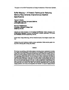
Consistent SDF graph Loosely interdependent subgraph Single-rate subgraph
4. SIMULATION-ORIENTED SCHEDULER The SOS approach integrates several existing and newly-developed graph decomposition and scheduling algorithms. Figure 1 illustrates the overall architecture of SOS. Among these techniques, LIAF, APGAN, and DPPO have been developed in [2], and the concept of recursive two-actor graph decomposition has been developed in [7]. These techniques were originally designed for code and data memory minimization in software synthesis, and
Flat
LIAF Acyclic graph SRC
Tightly interdependent subgraph Classical
Reduced multirate acyclic graph APGAN Topological sort DPPO Nested two-actor cluster hierarchy Two-Actor
Figure 1. Simulation-oriented scheduler architecture.
895
each R i results in a single-rate subgraph G i = ( R i, E i ) , where ∀e i ∈ E i , prd ( e i ) = cns ( e i ) ; 2) the clustering never introduces cycles into the clustered version of G ; and 3) each R i contains a maximal set of actors in order to effectively reduce G into a small multirate graph. Our SRC algorithm builds clusters through breadth-first search of adjacent actors. An actor v can be included in a subset R i if 1) every edge that connects v and R i is singlerate, and 2) there is no path between v and R i through other 2 actors. The running time of the SRC algorithm is E .
Given a connected, consistent SDF graph G = ( V, E ) , LIAF clusters all strongly connected components Z 1 …Z N into supernodes α 1 …α N , and this results in an acyclic graph G a to be further processed by subsequent algorithms. For each strongly connected subgraph G i = ( Z i, E i ) , LIAF tries to break cycles by removing edges that have “sufficient” delays. An edge e i ∈ E i can be removed in this sense if it has enough initial tokens to satisfy its sink actor’s consumption requirements for a complete iteration — i.e., if del ( e i ) ≥ cns ( e i ) × q G i [ snk ( e i ) ] . The buffer size of e i that is set aside in this way can be set to buf ( e i ) = del ( e i ) . G i is said to be loosely interdependent if after properly removing edges with sufficient delays, the modified version of G i is no longer strongly connected. If G i is found to be loosely interdependent, then LIAF is applied recursively to the modified version of G i . On the other hand, if G i is tightly interdependent (i.e., it is still strongly connected after removing all edges with sufficient delays), we apply the classical SDF scheduling algorithm.
4.5 Flat Scheduling Given a consistent, acyclic SDF graph G = ( V, E ) , a valid SAS can be easily derived by flat scheduling, which simply computes a topological sort of G and iterates each actor v q G [ v ] times. Flat schedules can be computed in linear time, but in general their memory requirements can be large. We apply flat scheduling only to single-rate subgraphs (SRSs); for SRSs, flat scheduling does not suffer from this memory overhead. This is because each actor only fires once within an SRS schedule. Thus, the buffer size of each SRS edge e can be set to buf ( e ) = prd ( e ) + del ( e ) , which is the minimum achievable size whenever del ( e ) < prd ( e ) .
The LIAF operations can be implemented in linear time (in terms of the number of actors V and the number of edges E in the input graph at each recursion). The complexity involved in the overall framework is dominated by the complexity of scheduling the G a s and G i s that it isolates in its top-down process of decomposition and clustering. The algorithms used in SOS for scheduling these graphs are discussed in Sections 4.3 through 4.8.
4.6 APGAN Scheduling In general, construction of a buffer-optimal SDF topological sort is NP-hard [11]. The acyclic pairwise grouping of adjacent nodes (APGAN) [2] is a heuristic to generate topological sorts. Given a consistent, acyclic SDF graph G = ( V, E ) , APGAN iteratively selects and clusters adjacent pairs of actors until the top-level clustered graph consists of just a single supernode. In each iteration, APGAN clusters a candidate adjacent pair { src ( e ), snk ( e ) } in the current version of G such that 1) clustering this pair does not introduce cycles; and 2) gcd ( q G [ src ( e ) ], q G [ snk ( e ) ] ) is maximized over all clustering candidates at the iteration. Once the clustering process is complete, a topological sort is obtained through depth-first traversal of the cluster hierarchy.
4.3 Classical SDF Scheduling As described in Section 3, classical SDF scheduling algorithm [9] is a greedy algorithm that fires an actor whenever it is fireable. By simulating this data-driven behavior, we can compute an actor firing sequence and the associated buffer sizes. The complexity of this algorithm is not polynomially bounded in the size of the input graph, and we use it only as a backup process for scheduling tightly interdependent subgraphs. Fortunately, this does not cause any major limitation in SOS because tightly interdependent subgraphs arise very rarely in practice [2]. For example, we have tested SOS on a suite of 126 WLAN designs and 267 3GPP wireless communications designs that, and among all of these applications, no tightly interdependent subgraphs were found.
2
The running time of APGAN is O ( V E ) [2]. At first, this appears high in relation to our objective of low complexity. However, due to the design of our SOS framework, which uses LIAF to recursively break cycles and isolate acyclic subgraphs, and uses SRC to further reduce the size of the acyclic subgraphs, V and E here are typically much smaller than the numbers of actors and edges in the overall SDF graph that is being scheduled. For the same reasons, we are able to apply the intensive DPPO and bufferoptimal two-actor scheduling algorithm discussed in Sections 4.7 and 4.8 within SOS without major degradation in simulation performance. This is beneficial because these two algorithms together with APGAN combine to provide significant reductions in the total buffer requirement.
4.4 Single-Rate Clustering In practical communication and signal processing systems, singlerate subsystems (subsystems in which all components and interconnections operate at the same average rate) arise commonly, even within designs that are heavily multirate at a global level. Since clustering single rate subsystems does not increase production and consumption rates at the interface of the resulting supernodes, we have developed the single-rate clustering (SRC) algorithm to further decompose an acyclic graph into a reduced (smaller) multirate version along with several single-rate subgraphs. Due to their simple structure, the single-rate subgraphs can be scheduled and optimized effectively by the accompanying flat scheduling (Section 4.5) in a very fast manner. Furthermore, the reduced multirate graph, which is scheduled using the more intensive techniques described in Sections 4.6-4.8, takes less time to schedule due to its significantly smaller size — that is, since each single-rate subsystem is abstracted as a single actor (supernode).
4.7 DPPO Scheduling The dynamic programming post optimization (DPPO) technique constructs a memory-efficient hierarchy of two-actor clusters from a topological sort L = v 1 …v V of actors in an acyclic SDF graph [2]. This hierarchy is constructed in a bottom up fashion by starting with two-actor subsequences v i v i + 1 in the topological sort and progressively optimizing the decomposition of longer subsequences. Each l -actor subsequence L i, j = v i …v j = i + l – 1 is “split” into “left’ L i, k = v i …v k and “right” L k + 1, j = v k + 1 …v j subse-
Given a consistent, acyclic SDF graph G = ( V, E ) , the SRC algorithm clusters disjoint subsets R 1 …R N ⊂ V such that 1) clustering
896
We first derive G * from G , then we compute two sequences of scheduling components s 1 …s I and s′ 1 …s′ I from G * . Each s j represents a looped sub-schedule that produces p j tokens, and has a firing sequence such that v snk is fired in an ASAP (as soon as possible) fashion — i.e., immediately, whenever fireable. Similarly, s′ j represents a looped sub-schedule that consumes c j tokens, and given c j tokens on e * , it also fires v snk in an ASAP fashion. The computation starts from s 1 = v src , s′ 1 = v snk , p 1 = p * , and c 1 = c * , and ends when p j is divisible by c j or vice versa. Because in this construction process, p j + c j is always equal to min ( p j – 1, c j – 1 ) , I , the number of iterations in the process, is bounded by log 2 ( min ( p *, c * ) ) .
quences in a buffer-efficient way. In particular, the split position k is chosen based on the minimum sum of buffering requirements associated with the left- and right-clusters plus the buffering requirements for the edges E i, j, k that cross from left to right. In SOS, we use an adapted form of DPPO where each subsequence split k is interpreted as a two-actor SDF graph G i, j, k = ( { α i, k, α k + 1, j }, E′ i, j, k ) such that the left- L i, k and right- L k + 1, j subsequences make up the two hierarchical actors α i, k and α k + 1, j . This two-actor graph is further optimized, after DPPO, by the buffer-optimal two-actor scheduling algorithm discussed in Section 4.8. The cost function for evaluating each candidate split is based on the minimum buffer requirement calculation for the two-actor scheduling algorithm, which efficiently derives buffer-optimal schedules for two-actor graphs.
From the results of this construction, we compute a schedule S . If d * = 0 , S can be immediately constructed from s I and s′ I . Otherwise, we first use s j and s′ j from j = 1 to I to consume the initial d * tokens on e * until either the token population on e * is 0 or we exhaust execution of v snk . Then we use s j and s′ j from j = I to 1 to make up the remaining firings of v src and v snk , and bring the token population on e * back to its initial state d * . S is a bufferoptimal schedule for G * as well as G because it fires v snk ASAP. The running time of this algorithm takes O ( log 2 ( min ( p *, c * ) ) ) .
3
The DPPO algorithm can be performed in O ( V ) time assuming that the number of input and output edges that are incident to any given actor is bounded by a constant. This is a reasonable assumption for practical SDF graphs in communications and signal processing applications, which are sparse in their structure [2]. Also, as in the previous section, the value of V is relatively small due to the preceding stages of LIAF- and SRC-based decomposition.
4.9 Overall Integration
4.8 Buffer-Optimal Two-Actor Scheduling
The overall integration of component algorithms in SOS is illustrated in Figure 1. A major contribution of this work is the selection, adaptation, and integration into a complete simulation environment of these component algorithms for the novel constraints associated with simulating critical SDF graphs.
The concept of recursive two-actor scheduling for a nested twoactor hierarchy was originally explored in [7]. For delayless SDF graphs, the resulting schedules are proven to be buffer-optimal at each (two-actor) level of the cluster hierarchy. These schedules are also polynomially bounded in the graph size [7]. However, the algorithm in [7] does not optimally handle the scheduling flexibility provided by edge delays, and therefore, it does not always achieve minimum buffer sizes in presence of delays. In this section, we present a new buffer-optimal two-actor scheduling algorithm that can compute a buffer-optimal schedule for a general consistent, acyclic two-actor SDF graph. This algorithm is applied in SOS to schedule each two-actor subgraph in the nested twoactor DPPO hierarchy obtained from Section 4.7.
In our implementation of SOS, we have also given attention to efficient management of the data structure that stores the computed schedule. In this data structure, each schedule loop is created only once, and multiple references to a schedule loop across the overall schedule are implemented as pointers to the single version. We apply this concept in the construction of scheduling components in the two-actor algorithm as well as in supernode-subschedule replacements across cluster boundaries. This implementation can significantly reduce the memory requirement for representing the overall schedule, and is more suited to the simulation-based context of this paper than the procedure-call based implementation format of [7], which is more suited to software synthesis.
Given a consistent, acyclic, two-actor SDF graph G = ( V, E ) as in Figure 2(a), we define the primitive form G * as in Figure 2(b), where ∀e i ∈ E , p i = prd ( e i ) , c i = cns ( e i ) , g i = gcd ( p i, c i ) , d i = del ( e i ) , and d * = min i ( d i ⁄ g i ) . We have proved that the minimum buffer requirement for e i is p i + c i – g i + d i – d * × g i if 0 ≤ d * ≤ p * + c * – 1 , and d i otherwise. This property provides a constant-time minimum buffer computation for G , and it is used in our adapted form of DPPO to evaluate the cost function of each split position. We have also proved that a minimum buffer schedule for G * is also a minimum buffer schedule for G , and based on this result, we develop our buffer-optimal two-actor scheduling algorithm.
pi = gi p* p|E| = g|E|p*
e1
...
vsrc
p1 = g1 p*
ei
...
G
e|E|
d1
c1= g1 c*
di
ci = gi c*
d|E| c|E| = g|E|c*
5. EXPERIMENTS In this section, we demonstrate the efficiency of our simulationoriented scheduler by scheduling and simulating today’s wireless communication systems in Agilent ADS [14]. For the experiments, we have implemented and integrated SOS in ADS. However, the design of SOS is not specific to ADS, and the techniques presented in this paper can be generally implemented in any simulation tool that incorporates SDF semantics. The experimental platform is a PC with 1GHz CPU and 1GB memory. In our experiments, we include 6 wireless communication designs from Agilent Technologies in the following standards: 3GPP, Bluetooth, 802.16e, CDMA 2000, and XM radio. Table 1 presents the characteristics of the 6 designs, including the number of actors, the number of edges (single-rate/multirate), and the approximate multirate complexity. These designs contain large numbers of actors and edges, and possess very high multirate complexity.
G*
vsnk
vsrc
p* d* c* e*
vsnk
Figure 2. (a) Two-actor SDF graph, and (b) primitive graph.
897
Table 1. Characteristics of wireless communication designs. Design
Standard
1 2 3 4 5 6
3GPP 3GPP Bluetooth 802.16e CDMA 2000 XM Radio
# of actors
ing and simulating modern wireless communication systems and other large-scale, highly multirate systems in the communications and signal processing domains. We have then presented the simulation-oriented scheduler (SOS). SOS integrates several existing and newly-developed graph decomposition and scheduling techniques in a strategic way for joint run-time and memory minimization in simulating critical SDF graphs. We have demonstrated the efficiency of our scheduler by simulating practical, large-scale, highly multirate wireless communication systems.
# of edges (single- Multirate rate / multirate) complexity
82 179 104 71 707 269
133 (101 / 32) 236 (194 / 42) 107 (97 / 10) 73 (49 / 24) 855 (805 / 50) 293 (245 / 48)
1.86 E6 1.10 E6 808 9.95 E6 3.83 E6 5.43 E6
7. REFERENCES
Table 2. Total Buffer requirements (in tokens). Design
CLS
1 2 3 4 5 6
50445629 9073282 3090 OOM in scheduling OOM in scheduling 48212523
SOS
[1] M. Ade, R. Lauwereins, and J. A. Peperstraete. Data memory minimization for synchronous data flow graphs emulated on DSP-FPGA targets. In Proc. of the Design Automation Conf., June 1997. [2] S. S. Bhattacharyya, P. K. Murthy, and E. A. Lee. Software Synthesis from Dataflow Graphs. Kluwer Academic Publishers, 1996. [3] J. T. Buck, S. Ha, E. A. Lee, and D. G. Messerschmitt. Ptolemy: A framework for simulating and prototyping heterogeneous systems. Intl. Journal of Computer Simulation, v.4, April 1994. [4] J. T. Buck. Scheduling Dynamic Dataflow Graphs with Bounded Memory Using the Token Flow Model. Ph.D. Thesis, UCB/ERL 93/69, Dept. of EECS, U. C. Berkeley, 1993. [5] J. T. Buck and R. Vaidyanathan. Heterogeneous modeling and simulation of embedded systems in El Greco. In Proc. of the Intl. Workshop on Hardware/Software Co-Design, May 2000. [6] J. Eker, J. W. Janneck, E. A. Lee, J. Liu, X. Liu, J. Ludvig, S. Neuendorffer, S. Sachs, and Y. Xiong. Taming heterogeneity — the Ptolemy approach. Proc. of the IEEE, v.91, No.1, Jan. 2003. [7] M. Ko, P. K. Murthy, and S. S. Bhattacharyya. Compact procedural implementation in DSP software synthesis through recursive graph decomposition. In Proc. of the Intl. Workshop on Software and Compilers for Embedded Processors, Amsterdam, The Netherlands, Sept. 2004. [8] R. Lauwereins, M. Engels, M. Ade, and J. A. Peperstraete. Grape-II: A system-level prototyping environment for DSP applications. IEEE Computer Magazine, 28(2):35-43, Feb. 1995. [9] E. A. Lee and D. G. Messerschmitt. Synchronous dataflow. Proceedings of the IEEE, 75(9):1235-1245, Sept. 1987. [10] P. Marwedel and G. Goossens, editors. Code Generation for Embedded Processors. Kluwer Academic Publishers, 1995. [11] P. K. Murthy, S. S. Bhattacharyya, and E. A. Lee. Joint minimization of code and data for synchronous dataflow programs. Journal of Formal Methods in System Design, 11(1), July 1997. [12] H. Oh, N. Dutt, and S. Ha. Single appearance schedule with dynamic loop count for minimum data buffer from synchronous dataflow graphs. In Proc. of the Intl. Conf. on Compilers, Architecture, and Synthesis for Embedded Systems, San Francisco, Sept. 2005. [13] H. D. Patel and S. K. Shukla. SystemC Kernel Extensions for Heterogeneous System Modeling, Kluwer Academic Publishers, 2004. [14] J. L. Pino and K. Kalbasi. Cosimulating synchronous DSP applications with analog RF circuits. In Proc. of the IEEE Asilomar Conf. on Signals, Systems, and Computers, Pacific Grove, CA, Nov., 1998. [15] C. B. Robbins. Autocoding Toolset Software Tools for Automatic Generation of Parallel Application Software. Technical report, Management Communications and Control, Inc., 2002. [16] T. Stefanov, C. Zissulescu, A. Turjan, B. Kienhuis, and E. Deprettere. System design using Kahn process networks: the Compaan/Laura approach. In Proceedings of the Design, Automation and Test in Europe Conference, Feb. 2004. [17] W. Sung, M. Oh, C. Im, and S. Ha. Demonstration of hardware software codesign workflow in PeaCE. In Proc. of Intl. Conf. on VLSI and CAD, Oct. 1997.
Ratio (CLS/SOS)
229119 43247 3090 669273 9957292 5385031
220 210 1 N/A N/A 9
Table 3. Average scheduling time (in seconds). Design
CLS
1 2 3 4 5 6
0.08 279.11 0.06 OOM in scheduling OOM in scheduling 10.72
SOS
Ratio (CLS/SOS) 0.08 0.16 0.06 0.45 13.5 0.67
1 1744 1 N/A N/A 16
Table 4. Average total simulation time (in seconds). Design
CLS
1 2 3 4 5 6
OOM in simulation 349.33 930.56 OOM in scheduling OOM in scheduling OOM in simulation
SOS 7.12 55.31 876.72 203.95 2534.06 406.86
Ratio (CLS/SOS) N/A 6.32 1.06 N/A N/A N/A
We simulate the 6 designs with our simulation-oriented scheduler (SOS) and the present default cluster-loop scheduler (CLS) in ADS. The simulation results of CLS, SOS, and the performance ratio (CLS/SOS) are shown in three tables: Table 2 presents the total buffer requirements for SDF edges (in number of tokens); Table 3 presents the average scheduling time of ten runs (in seconds); and Table 4 presents the average total simulation time of ten runs (in seconds). As shown in these tables, SOS outperforms CLS in all designs in terms of memory requirements, scheduling time, and total simulation time (except design 3, which is comparable due to its relatively small multirate complexity). CLS fails in scheduling design 4 and 5, and also fails in simulating design 1 and 6 due to out-of-memory (OOM) problems. For design 2, CLS requires very long scheduling time due to its heavy dependence on the classical scheduler.
6. CONCLUSION In this paper, we have introduced and illustrated the challenges in scheduling large-scale, highly multirate SDF graphs for simulation tools that incorporate SDF semantics. We have defined critical SDF graphs as an important class of graphs that must be taken carefully into consideration when designing such tools for model-
898