Bull. Chem. Soc. Ethiop. 2006, 20(2), 279-293. Printed in Ethiopia
ISSN 1011-3924 2006 Chemical Society of Ethiopia
ELECTROCHEMICAL PROPERTIES AND ELECTROCHEMICAL IMPEDANCE SPECTROSCOPY OF POLYPYRROLE-COATED PLATINUM ELECTRODES M. Falla*, A.A. Diagne a, M. Guène a, C. Della Volpe b, P.L. Bonora b, F. Deflorian b, S. Rossi b a
Groupe de Recherches en Electrochimie et Sciences des Polymères (GRESP – LCPOAI, TWAS Research Unit 02-004 LDC/CHE/AF/AC), Département de Chimie, Faculté des Sciences et Techniques, Université Cheikh Anta Diop, BP 5085 Dakar, Sénégal b Department of Materials Engineering and Industrial Technologies, University of Trento, 38050 Trento, Italy (Received October 20, 2005; revised January 31, 2006) ABSTRACT. Polypyrrole (PPy) films of different thickness were characterized by electrochemical impedance spectroscopy (EIS) measurements in acetonitrile and aqueous solutions, containing 0.1 M NaClO4 or sodium dodecylsulfate as the dopant. The PPy films were electrochemically deposited on Pt, and their electrochemical properties studied by cyclic voltammetry. Impedance spectra were obtained at potentials ranging from 0 to 0.8 V/SCE. The EIS data were fitted using two different equivalent electrical circuits (depending on the nature of the dopant). They involve a diffusive capacitance, which increased with the passing charge during electrosynthesis (i.e. film thickness) for ClO4--doped PPy, but was practically unaffected by the film thickness in the case of SDSdoped PPy. Also, a double-layer capacitance was found only in the circuit of ClO4--doped PPy. It increased with the film thickness, and showed a minimum near the open-circuit potential. Finally the charge-transfer resistance (Rct) obtained with SDS is nearly 200-fold higher than that obtained with ClO4- in the same solvent (H2O). With the same dopant (ClO4-), Rct is about five times higher in acetonitrile relative to water. All these EIS results of the different types of PPy suggest a relation with the wettability of the polymer. KEY WORDS: Conducting polymers, Polypyrrole, Electrochemical impedance spectroscopy, Equivalentelectrical circuit, Micellar media
INTRODUCTION Polypyrrole (PPy) and its derivatives, obtained either by chemical [1-6] or electrochemical [7-16] oxidation of the corresponding monomers, have been the subject, during the last years, to a large number of studies because of their many potential applications including gas sensors [17], transistors [18-20], photovoltaic cells [21], energy storage [22-28], protective coatings [29-32], etc. The electropolymerization of pyrrole and derivatives have been realized in organic media [8-12], aqueous or micellar media (presence of surfactants) [13-16, 33-35]. In all cases, the resulting polypyrroles were obtained as adherent conductive films on metallic surfaces, such as platinum or oxidizable metals [29-32]. The electrical and mechanic properties, as well as the morphology of the PPy films were found to depend on the doping anion, which can be ClO4-, PF6-, dodecylsulfate, dodecylbenzenesulfonate, etc. [6, 7]. The PPy films have been characterized by many spectroscopic methods, including FT-IR and Raman spectroscopy, XPS analysis, etc. [7]. The electrochemical characterization of PPy films was also realized, and showed unsymmetric oxidation and reduction peaks, describing the doping/undoping processes [28-30]. Electrochemical impedance spectroscopy (EIS) has been found to be a powerful tool to study charge transfer, ion diffusion and capacitance of conducting polymer-modified electrodes [36]. Recently, some works have been devoted to the EIS characterization of PPy doped with ClO4- on ITO [37], a membrane of PPy/tetraethylammonium tosylate deposited on Pt [38], __________ *Corresponding author. E-mail:
[email protected]
280
M. Fall et al.
insulating PPy formed on Pt [39]. Other authors studied by EIS the behavior of PPy composites prepared with high molecular weight dopants: PPy/polystyrenesulphonate on Pt [40], PPy/polyimide [41] on stainless steel sheets, etc. In our previous works, we studied the electrosynthesis and electrochemical characterization of poly(3-methoxythiophene) (PMOT) in aqueous micellar media (in the presence of different types of surfactants [42-44]. Very recently, we realized the EIS characterization of PMOT in aqueous LiClO4 solutions [45]. However PMOT films cannot be obtained in organic media because of the solubility of this conducting polymer in organic solutions. The study of the solvent effect on the EIS properties is therefore unfeasible on PMOT. In contrast, PPy films can be electrodeposited in metallic substrates either in organic media, or in aqueous ones because of its insolubility. In this paper, we study the electrochemical properties and propose a EIS analysis of PPy films electrosyhthesized on Pt. In these preliminary works on PPy, we will examine two types of dopants and two different solvents: NaClO4 as dopant in water (PPy/ClO4-/w) and in acetonitrile (PPy/ClO4-/acn), and sodium dodecylsulfate in water (SDS) (PPy/SDS).
EXPERIMENTAL Chemicals and apparatuses The monomer (pyrrole, 98 %) and sodium dodecylsulfate (SDS 99 %) were obtained from Aldrich. Pure sodium perchlorate was purchased from Riedel-de-Haën. All these reagents were freshly purchased and have been used without further purification. The PPy electrosynthesis was carried out using an EG & G Princeton Applied Research Potentiostat/Galvanostat Model 283. This apparatus, coupled with a Schlumberger SI 1255 Frequency Response Analyzer, was also used in the EIS measurements. Polymer electrodeposition Polypyrrole films were electrochemically obtained, by applying a constant current density (1 mA/cm2) during 150, 300, 450, 600 or 900 s. In this range, the film thickness varies linearly with the passing charge [46-47]. The electrodeposition was performed in a one-compartment cell, containing the working electrode (a Pt disc with 1 cm diameter), the reference electrode (saturated calomel electrode, +242 mV/NHE, referred henceforth as SCE), and the counterelectrode (stainless steel wire). Prior to use, the working and the counter electrodes were cleaned with acetone in an ultrasonic bath. The electrolytic medium of electrosynthesis was prepared by dissolving 0.1 M pyrrole + 0.1M NaClO4 in water (PPy/ClO4-/w), 0.1 M pyrrole + 0.1 M SDS in water (PPy/SDS) and 0.1M pyrrole + 0.1 M NaClO4 in acetonitrile (PPy/ClO4/acn). The PPy thus electrosynthesized is in its oxidized form and holds ClO4- or dodecylsulfate anions, as dopants (doping level: 25-30 % [7]). It was washed with distilled water or acetonitrile (according to the medium of preparation), dried with air and used like this in the impedance measurements. EIS measurements EIS measurements were carried out on the PPy films at various DC potentials (referred hereafter as Edc) by applying 5 mV AC on the DC potential at frequencies ranging from 100 kHz to 0.01 Hz, with 5 points/decade. The impedance data were fitted to equivalent electrical circuits by Bull. Chem. Soc. Ethiop. 2006, 20(2)
Electrochemical impedance spectroscopy of polypyrrole-coated Pt electrodes
281
using Boukamp’s fitting program [48]. Because of a loss of accuracy at too high or too low frequencies, the simulations were limited in the range 10 kHz - 0.1 Hz. In a series of measurements on a particular sample, we started by the open-circuit-potential (OCP or E0), evaluated just before any EIS running. In the following experiments, the applied DC potentials were, sequentially: E0 -0.1, E0 -0.2, E0 -0.3, E0 +0.1, E0 +0.2, and E0 +0.3 V/SCE. Before each EIS measurement, the electrode was hold during an equilibrium time of 5 min.
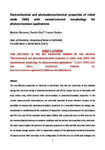
RESULTS AND DISCUSSION Electrodeposition and electrochemical characterization of polypyrrole The electropolymerization of pyrrole was carried out via the galvanostatic route (Figure 1.), by applying a constant current density (1 mA/cm2) and varying the polarization time (150, 300, 450, 600 or 900 s). The curves are characterized, after a short period of induction, by horizontal lines, indicating the different oxidation potentials of the monomer in the different media: 0.61, 0.64 and 0.81 V/SCE, in, respectively, aqueous SDS, aqueous NaClO4 and acetonitrile NaClO4 solutions. The measured potentials can be expressed as: E = E0 + (ΣR) x I,
E / V vs SCE
where E is the measured potential, E0 the oxidation potential of the monomer (pyrrole), I the current intensity and ΣR the overall ohmic resistance between the counter-electrode and the working electrode. The higher specific resistance of the organic solution relative to water explains the fact that the potential is higher in acetonitrile than in water. 0.9
PPy/ClO 4 - /acn
0.8
0.7
PPy/ClO 4 - /w 0.6
PPy/SD S
0.5
0.4
0
200
400
600
800 t/s
Figure 1. Chronopotentiometric curves of electrodeposition of PPy films (i = 1 mA/cm2). Despite the fact that the aqueous SDS solution is less conductive than the aqueous NaClO4 one, the oxidation potential of Py in the presence of the surfactant is lower than that observed in the absence of SDS in the same solvent. Previously, we noted a similar decrease of the oxidation potential of several thiophene derivatives [44, 49-50], which was assigned to trapping of the monomers in micelles formed by many SDS units. The formation of these complex-like structures leads to a lowering of the oxidation potential. Bull. Chem. Soc. Ethiop. 2006, 20(2)
282
M. Fall et al.
On the other hand, during the electropolymerization (oxidation and linking of the monomer units), the films hold substantial quantities of anions to maintain electroneutrality (doping of the polymer) [7-16, 28-30]. The doping/undoping phenomena of the polymer film can be described by the reactions shown in Scheme 1. x+
I
H . x ClO4− + x e− n
H N
H + x ClO4− n
H N
y+
II
H
n
N
H . y DS− + y e−
H + y DS− n
H N
Scheme 1. Doping and undoping reaction schemes for PPy/ClO4-/w (I) and PPy/ClO4-/acn (I) and PPy/SDS (II).
i / mA/cm2
The dodecylsulfate anion (DS-), because of its long hydrophobic chain, diffuses difficultly in the polymer film. PPy/SDS appears therefore to be more resistant than PPy/ClO4-/w. These features are noticed when we perform voltammograms of the different types of PPy, in the medium used during electrosynthesis, but free of monomer (Figures 2-4). The voltammograms are characterized by one anodic peak, ascribed to the insertion of anions, which is significantly faster than cations expulsion [40]. The oxidation and reduction peak potentials are given in Table 1. They are strongly dependent on the scan rate, in water. The peak current density varies linearly with the scan rate for PPy/ClO4-/w and PPy/ClO4-/acn, which indicates a reaction ratecontrolled process (the diffusion is faster than the charging process). This is typical of reactions of substances grafted on an electrode, like polymer films [51]. In contrast, for PPy/SDS, the peak current density varies linearly with the square root of the scan rate. The ion diffusion (most likely rather in the film than in the bulk electrolyte) is in this case slower [51], presumably because of the high length of the DS- chain. The electrochemical process is therefore controlled by the ion diffusion. 6 a
4 b
2 c
0
d
d c
-2
b a
-4 -6 -1.0
-0.5
0.0
0.5
1.0
E / V vs SCE
Figure 2. Electroactivity of PPy/ClO4-/w (obtained after 600 s) in aqueous 0.1 M NaClO4. Scan rate: a): 50, b): 25, c): 10 and d) 5 mV/s. Bull. Chem. Soc. Ethiop. 2006, 20(2)
i / mA cm-2
Electrochemical impedance spectroscopy of polypyrrole-coated Pt electrodes
283
6 4
a b
2
c d
0
d c
-2 b
-4 a
-6 -1.0
-0.5
0.0
0.5
1.0
E / V vs SCE
i / mA cm-2
Figure 3. Electroactivity of PPy/SDS (obtained after 600 s) in aqueous 0.1 M SDS. Scan rate: a): 50, b): 25, c): 10 and d) 5 mV/s. 6 4
a
2
b c d
0 c b
-2 a
-4 -6 -1.0
-0.5
0.0
0.5
1.0
E / V vs ECS
Figure 4. Electroactivity of PPy/ClO4-/acn (600 s) in acetonitrile 0.1 M NaClO4. Scan rate: a): 50, b): 25, c): 10 and d) 5 mV/s. Table 1. Oxidation and reduction peak potentials (Epox and Epred, in mV/SCE) and equilibrium potentials (Eeq = (Epox + Epred)/2, in mV/SCE) on the voltammograms of the different types of PPy electrodeposited at 1 mAcm-2 during 600 s. V (mV/s) PPy/ClO4-/w PPy/ClO4-/acn PPy/SDS a a
50
25
10
Epox
Epred
Eeq
Epox
Epred
Eeq
Epox
450 191 -118
-296 77 -682 -245 -960 -539
250 97 -264
-188 -497 -824 (-692)
31 -200 -544
116 57 -315
Epred
5 Eeq
Epox
Epred
Eeq
-136 -10 -383 -163 -744 -529 (-502)
33 8 -328
-68 -230 -684 (-156)
-17 -111 -506
The shoulder potential is given between brackets.
Bull. Chem. Soc. Ethiop. 2006, 20(2)
284
M. Fall et al.
The cathodic part of the curves presents more broadened peaks. In the case of PPy/ClO4-/w, a peak appearing between -0.3 and -0.07 V/SCE (according to the scan rate) can be observed, whereas, for PPy/SDS, an intense peak is located between -0.96 and -0.68 V/SCE (see Table 1), which is coupled with a shoulder at ca -0.69, -0.50 and -0.16 V/SCE for the three lower scan rates. It is however widened by the main peak at high scan rates (50 mV/s). The shoulders can be attributed to the undoping of the polymer, accompanied by a release of anions, and the peak with the more negative potential to an up-take of cations (Na+) [52-55]. This latter type of undoping is therefore predominant in PPy/SDS. SDS is really difficult to remove from the film, not only due to the high size of the surfactant alkyl chain, but also because of the presence of polar and apolar extremities of its molecule, the former being compatible with the charged (oxidized) form of the molecule, and the latter with the neutral backbone [13]. In the case of PPy/ClO4-/acn, a "rectangular" wave appears in the cathodic region, with maxima at values ranging from -0.68 to -0.23 V/SCE, according to the scan rate (see Table 1). The mean value of the oxidation and reduction peak potentials (equilibrium potential, noted Eeq in Table 1) is also presented. The different potentials of the different types of polymers are such as:
EPPy/ClO4-/w > EPPy/ClO4-/acn > EPPy/SDS
Q /C cv
This might indicate a degree of polymerization (number of monomeric units) varying in the same sequence [7]. The voltammograms have been used to evaluate the amount of undoping charge (Qcv), by integration of the curves of electroactivity of the different types of PPy in the corresponding electrolytes, which can be compared to the passing charge during electrosynthesis (Qp) (Figure 5). The plots can reasonably be considered as linear. It follows that the passing charge parallels the coulometry of the films in pure electrolyte, and therefore the film thickness. The amount of polypyrrole (~ Qcv) electrodeposited on the Pt electrode is therefore proportional to the amount of charge injected during electrosynthesis, and the ratio is only slightly dependent on the different conditions used for the electropolymerization. 0 .0 8
P P y /C lO 4 -/w : Q c v = 0 .1 3 x Q p P P y /C lO 4 - /a c n : Q c v = 0 .1 6 x Q p P P y /S D S : Q c v = 0 .1 2 x Q p
0 .0 6
0 .0 4
0 .0 2
0 .0 0 0 .0
0 .2
0 .4
0 .6
0 .8 Qp / C
Figure 5. Amount of charge necessary for the undoping of the different polymers, vs. charge injected during the electrosynthesis. Qcv was obtained by integration of the voltammetric curves of the polymers at v = 25 mV/s.
Bull. Chem. Soc. Ethiop. 2006, 20(2)
Electrochemical impedance spectroscopy of polypyrrole-coated Pt electrodes
285
EIS results General aspect of the EIS spectra
2 -Zim / Ω cm
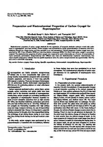
The general aspect of the impedance and admittance curves is presented in Figures 6-8. In the explored frequency region, two distinct parts can be noticed for the films prepared in the presence of sodium perchlorate: a portion of semicircle in the region 10000-2Hz (PPy/ClO4-/w, Figure 6) and 10000-0.6 Hz (PPy/ClO4-/acn, Figure 7), and an oblique line between 2 and 0.1 Hz (PPy/ClO4-/w, Figure 6) and 0.4 and 0.1 Hz (PPy/ClO4-/acn, Figure 7). For PPy/SDS, the semicircle portion is not observed. We have a quite linear evolution of -Zim vs Zre between 10000 and 0.1 Hz (Figure 8). The general aspect of the curves was not affected by the electropolymerization charge, which is proportional to the film thickness in the prospected region. In the range of potentials explored (0.08-0.58 V/SCE), the electrochemical phenomena are traduced by the insertion/release of anions, as depicted in Scheme 1.
0 .1 H z
60
40
20
10 kH z
0 0
20
40
60 Z re / Ω cm 2
Figure 6. Impedance curves of the Pt/PPy/ClO4-/w-coated electrodes (E0 = 0.33 V/SCE). The test-solution was aqueous 0.1 M NaClO4, and the applied potential 0.08 (■) and 0.58 V/SCE (○). The films were obtained by applying 1 mA/cm2 during 450 s. The linear portion, appearing in the lower frequency region, is probably a Warburg impedance (diffusion-controlled process), while the semicircle portion found at high frequency for PPy/ClO4-/w and PPy/ClO4-/acn, but not for PPy/SDS, indicates presumably a double-layer capacitance. The presence of a single Warburg in the impedance spectra of PPy/SDS corroborates the results of the electrochemical characterization of the films, which showed that the electrochemical process is rather diffusion-controlled for PPy/SDS only.
Bull. Chem. Soc. Ethiop. 2006, 20(2)
286
M. Fall et al.
-Z
im / kΩ cm
2
Figure 7. Impedance curves of the Pt/PPy/ClO4-/acn-coated electrodes (E0 = 0.62 V/SCE). The test-solution was acetonitrile 0.1 M NaClO4 and the applied potential 0.08 (■) and 0.58 V/SCE (○). The films were obtained by applying 1 mA/cm2 during 450 s.
4 0 .1 H z
3
2
1 10 kH z 0 0
1
2
3
4
Zre / kΩ cm
2
Figure 8. Impedance curves of the Pt/PPy/SDS-coated electrodes (E0 = 0.18 V/SCE). The testsolution was aqueous 0.1 M SDS and the applied potential 0.08 (■) and 0.58 V/SCE (○). The films were obtained by applying 1 mA/cm2 during 450 s. Equivalent circuit In order to analyze the EIS results, we fitted the impedance data to equivalent electrical circuits (EEC) by using Boukamp’s fitting program [48]. We obtained good fittings for frequencies ranging from 10000 to 0.1 Hz (χ2 ≈ 10-5-10-4) by using the equivalent electrical circuits depicted in Scheme 2.
Bull. Chem. Soc. Ethiop. 2006, 20(2)
Electrochemical impedance spectroscopy of polypyrrole-coated Pt electrodes
W
287
W
Rs
Rs Rct
Rct
Q3 a
b -
Scheme 2. Equivalent electrical circuits for the PPy/ClO4 /w (a) PPy/ClO4-/acn and PPy/SDS (b) electrodeposited on Pt electrodes The first circuit consists of a first resistance (solution resistance Rs), in series with a branch composed of a constant-phase element with exponent values of 0.38-0.67 for PPy/ClO4-/w and PPy/ClO4-/acn, and 0.6-0.7 for PPy/SDS. These exponent values, close to 0.5, indicate a diffusion-controlled process. This capacitance is therefore ascribed to the diffusive capacitance (or Warburg Impedance, noted W). W is in parallel with the faradic component, which is composed, in the case of PPy/ClO4-/w and PPy/ClO4-/acn (Scheme 2a), of a resistance (Rct) serially associated with a capacitance (Q3). Rct is the sum of the charge transfer and the film ohmic resistances, while Q3, with exponent values of 0.97-1, is the double-layer capacitance. As previously noted in the spectra, the double-layer capacitance disappears in the EEC for PPy/SDS (Scheme 2b), and Rct is therefore essentially due to the film ohmic resistance. In the next sections, we are describing the study of the evolution of Rs, W, Q3 and Rct with the passing charge (i.e. film thickness) and the applied potential. Solution resistance The solution resistance (Rs) is less significant because it depends on the counter-electrode position, and this explains the variations observed when going from a given passing charge to another. Rs can unsurprisingly be considered as independent of the electropolymerization time and the applied potential, as can be seen in Table 2. The resistance of NaClO4 solution appears to be higher in acetonitrile than in water. This result corroborates the interpretation previously given for the high value of the oxidation potential of Py in acetonitrile relative to water. Table 2. Solution-test resistance (Ω.cm2), obtained after fitting impedance results to electrical-equivalentcircuits depicted in scheme 2 (mean values of Rs for the different applied potentials). Passing charge (C) PPy/ClO4-/w a PPy/ClO4-/acn b PPy/SDS c a
0.150 29.7 ± 0.2 76.4 ± 0.9 27.8 ± 0.2
0.300 27.5 ± 0.5 90.4 ± 0.8 21.8 ± 0.1
0.450 24.3 ± 0.4 75.0 ± 1.4 21.2 ± 0.2
0.600 24.3 ± 0.4 75.5 ± 0.6 25.3 ± 1.2
0.900 29.8 ± 0.7 77.7 ± 1.0 17.9 ± 0.3
Aqueous 0.1 M NaClO4; b acetonitrile 0.1 M NaClO4; c aqueous 0.1 M SDS.
Diffusive capacitance The diffusive capacitance (W) increases with the passing charge for PPy/ClO4-/acn and PPy/ClO4-/w, as can be seen on Figure 9 for PPy/ClO4-/w. In the case of PPy/SDS (Figure 10), W seems more or less to be unaffected by the passing charge. No solvent effect was noticed, because of the good similarity of the diffusive capacitances of the PPy films obtained with ClO4as dopant in water and in acetonitrile. The high values of W (2-15 mF.cm-2 for PPy/ClO4-/w and PPy/ClO4-/acn) indicate a high diffusion speed of ClO4-. Regarding the increasing of W with the film thickness, a similar behavior has been reported for a polybithiophene film and was Bull. Chem. Soc. Ethiop. 2006, 20(2)
288
M. Fall et al.
-2 W / mF cm
attributed to changes in the morphology when the thickness increases [56]. These morphology changes could affect the mobility of the ion in the polymer matrix, and therefore the film capacitance. For the PPy/SDS films, the Warburg impedance has much lower values (0.2-0.4 mF cm-2), seems practically unaffected by the film thickness, and increases with the applied potential (Figure 10), with a likely maximum at 0.3-0.4 V/SCE. The only weak film thickness effect on PPy/SDS diffusive capacitance can be due to a possible higher intrinsic resistance of these films, because of the lower PPy/SDS doping level. This resistance increases with the film thickness and moderates the doping/undoping rate. For instance, for insulating polypyrrole, the capacitance decreases with the applied potential [39]. On the other hand, the PPy/SDS Warburg impedance clearly increases with the applied potential, and seems to reach a maximum at 0.40.5 V/SCE (Figure 10). This is in accordance with the observations and interpretation given by Tanguy et al. [52, 57]. In their works, they identified two types of ionic trapping sites in polypyrrole films: deeply or apparently trapped ions. The amount of the deeply trapped ions, which cannot follow the AC signal, increases during the film charging, i.e. the few ions that have entered the film remain in a quasi-free state. When the potential increases, the amount of quasi-free ions increases and reaches a maximum, giving a maximum film capacitance. This behavior is seriously reliable in the case of PPy/SDS because of the high size of the dopant, which is difficult to remove from the film. Furthermore, in this interpretation, there are two types of current in the cyclic voltammetry: a capacitive current without hysterisis effect, and a non-capacitive current, arising from the deeply trapped ions, giving a large hysterisis which is responsible for the broadening of the peaks. This non-capacitive current is here diffusional, and is predominant in the case of PPy/SDS. 16
12
8
4
0 0 .2
0 .4
0 .6
0 .8
1 .0
Q / C
Figure 9. Evolution of the diffusive capacitance of the PPy/ClO4-/w electrodes with the passing charge. The applied potential was 0.08 (■), 0.18 (●), 0.28 (▲) and 0.48 (□) V/SCE. The diffusive capacitance of PPy/ClO4-/w decreases with the potential applied during the EIS measurements in the prospected region (0.08- 0.60 V/SCE), except for the thinner films. The undoping process is therefore faster than the doping one. This was observed during the study of the electroactivity of PPy/ClO4-/w films: the reduction peaks were larger than the oxidation ones, as can be seen in Figure 2.
Bull. Chem. Soc. Ethiop. 2006, 20(2)
Electrochemical impedance spectroscopy of polypyrrole-coated Pt electrodes
289
W / mF.cm-2
0.6
0.4
0.2
0.0 0.2
0.4
0.6
0.8 Q/C
Figure 10. Variation of the diffusive capacitance of the PPy/SDS electrodes with the passing charge. The applied potential was 0.08 (■), 0.28 (●), 0.38 (□) and 0.48 V/SCE (○). Double-layer capacitance
Q3 / mF cm-2
The double-layer capacitance also increases with the film thickness for PPy/ClO4-/w and PPy/ClO4-/acn (see Figures 11 and 12). This is in accordance with results already obtained with some polythiophene derivatives [45, 56], but also in the case of PPy/polyimide copolymer, doped with KPF6 [41]. In our case, the increasing of the double-layer capacitance with the passing charge during electropolymerization may be ascribed to an increase of the doping level of the polymer (ratio ClO4-/PPy+) which results in increased pseudocapacitance. The value of the double-layer capacitance is however minimal just after the open-circuit potential (OCP). This capacitance may characterize the film surface, and then the second ionic trapping sites, i.e. the not deeply trapped ions identified by Tanguy et al. [52, 57] (see diffusive capacitance section). The amount of the ions on the film surface decreases when we approach the equilibrium potential and reaches a minimum, giving a minimum film capacitance. We believe hence that Q3 occurs at the interface polymer/electrolyte. The higher values of ClO4--doped PPy double-layer capacitance in water (7-36 mF.cm-2) than in acetonitrile (5-21 mF.cm-2) and its absence in the micellar medium (when the surfactant is used) may suggest a relation with the wettability of the polymer. 40
30
20
10 0.0
0.2
0.4
0.6 Edc / V/SCE
Figure 11. Double-layer capacitance of PPy/ClO4-/w electrodes against the applied potential. The passing charge was 0.15 (■), 0.30 (●), 0.45 (□), 0.60 (○) and 0.90 C (▲). E0 ≈ 0.38 V/SCE. Bull. Chem. Soc. Ethiop. 2006, 20(2)
M. Fall et al.
Q3/mF cm-2
290
20
16
12
8
0.4
0.6
0.8
Edc/V vs SCE Figure 12. Double-layer capacitance of PPy/ClO4-/acn electrodes against the applied potential. The passing charge was 0.15 (■), 0.30 (●), 0.45 (□) and 0.90 C (▲). E0 ≈ 0.61 V/SCE. Charge transfer + film resistance For the charge transfer + film ohmic resistance (named Rct), the plots show in all cases a logical increase with the film thickness. We have a quite constancy between 0.08 and 0.58 V/SCE, Rct ranging from 7 to 40 Ω.cm2 (PPy/ClO4-/w, see Figure 13). After 0.58 V/SCE, we observe an abrupt increasing of Rct, probably due to an over-oxidation of the polymer in water. The quasistability of Rct is obtained between 0.2 and 0.9 V/SCE, Rct ranging from 35 to 215 Ω.cm2 in the case of PPy/ClO4-/acn. When doped with ClO4-, the films remain highly conductive and the charge transfer is rapid, even around the OCP potential. The higher values of Rct may indicate that when prepared galvanostatically under the same conditions (same current density and polymerization time), PPy/ClO4-/acn films are thicker than PPy/ClO4-/w films. In the case of PPy/SDS, we can observe in Figure. 14 a first increase, followed by a diminution after the equilibrium potential. This may be associated with the evolution of the amount of trapped ions (anionic and cationic), which reaches a maximum at the open-circuit potential. In fact, during the reduction, in addition to the release of anions (especially when high molecular weight dopants are concerned), cations enter the film, as previously shown by other authors [6, 13, 40]. The presence of this well-defined maximum at the OCP potential, which is absent when the dopant is ClO4- and the remarkably high values of Rct (1.5-24 kΩ.cm2) proves the problematical charge transfer in this polymer because of the difficulty to extract dodecylsulfate anions from the film. Finally, Rct is not in parallel with the double-layer capacitance in the circuits of PPy/ClO4-/w and PPy/ClO4-/acn (Scheme 2), as sometimes observed for thinner films [46], but in series; the reason may be the fact that this charge-transfer resistance characterizes doping/undoping phenomena occurring in the heart of the film.
Bull. Chem. Soc. Ethiop. 2006, 20(2)
Rct / Ω.cm
2
Electrochemical impedance spectroscopy of polypyrrole-coated Pt electrodes
291
100
80
60
40
20
0.0
0.2
0.4
0.6
E dc / V vs SCE
2 Rct / kΩ.cm
Figure 13. Charge transfer + film resistance of PPy/ClO4-/w electrodes vs. the applied potential. The passing charge was 0.15 (■), 0.30 (●), 0.60 (○) and 0.90 C (▲). E0 ≈ 0.38 V/SCE. 25 20
0.60 C
15 10
0.45 C
5 0
0.30 C -0.2
0.0
0.2
0.4
0.6
Edc / V vs SCE
Figure 14. Charge transfer + film resistance of PPy/SDS electrodes vs. the applied potential. The passing charge was 0.30 (●), 0.45 (□) and 0.60 C (○). E0 ≈ 0.16 V/SCE.
CONCLUSIONS In this work, we realized the electrochemical and EIS characterization of polypyrrole thin films deposited on Pt and doped with sodium perchlorate in water and in acetonitrile, and with sodium dodecylsulfate in water. The EIS result confirmed the voltammetric characterization of the films. In the presence of NaClO4, the spectra showed a double-layer capacitance, associated Bull. Chem. Soc. Ethiop. 2006, 20(2)
292
M. Fall et al.
with a Warburg capacitance, while in the micellar medium only the diffusive capacitance is observed. This was related to the high size of this dopant. The impedance measurements showed that the film obtained within this medium is not far from an insulator. Furthermore, the comparison between the double-layer capacitance in acetonitrile and in water, and the fact that it disappears when the film is electrosynthesized using the surfactant lead us to the conclusion that the surface tension of the electrolyte medium (of synthesis and characterization) can influence the electrochemical properties and EIS performances of a conducting polymer like polypyrrole. The EIS measurements are continuing on other conducting polymers, other solvents and other electrolytes. We are also presently performing contact angle measurements on a series of conducting polymers in order to investigate deeply this conjecture.
AKNOWLEDGEMENTS This work was partly supported by the Third Word Academy of Sciences (TWAS) throughout a project grant to the Senegalese Research Group in Electrochemistry and Polymer Science (TWAS Research Unit N° 04-050 LDC/CHE/AF/AC). REFERENCES 1. 2. 3. 4. 5. 6. 7. 8. 9. 10. 11. 12. 13. 14. 15. 16. 17. 18. 19. 20. 21. 22. 23.
Travers, J.P.; Audebert, P.; Bidan, G. Mol. Cryst. Liq. Cryst. 1985, 118, 149. Mermilloid, M.; Tanguy J.; Petiot, F. J. Electrochem. Soc. 1986, 133, 1073. Wu, H.M.; Shy, H.J.; Ko, H.W. J. Power Sources 1989, 27, 59. Nishio, K.; Fujimoto, M.; Yoshinaga, N.; Furukawa, N.; Ando, O.; Ono, H.; Suzuki, T. J. Power Sources 1991, 34, 153. Nishio, K.; Fujimoto, M.; Ando, O.; Ono, H.; Murayama, T. J. Appl. Electrochem. 1996, 26 425. Kaplin, D.A.; Qutubuddin, S. Synth. Met. 1994, 63, 187. Tourillon, G. Handbook of Conducting Polymers, Vol. 1, Marcel Dekker: New York; 1986; p 294. Diaz, A.F.; Kanazawa, K.K. J. Chem. Soc. Chem. Comm. 1979, 635. Feldmen, B.J.; Burgmayer, P.; Murray, R.W. J. Am. Chem. Soc. 1985, 107, 872. Naoi, K.; Sakai, H.; Ogano, S.; Osak, T. J. Power Sources 1987, 20, 237. Marcos, M.L.; Rodriguez, I.; Gonzalez-Velasco, J. Electrochim. Acta 1987, 32, 1453. Warren, L.F.; Anderson, D.P. J. Electrochem. Soc. 1987, 134, 101. Panero, S.; Prosperi, P.; Scrosati, B. Electrochim. Acta 1992, 37, 419. Collard, D.M.; Stoakes, M.S. Chem. Mater. 1994, 6, 850. Coche Guérente, L.; Deronzier, A.; Galland, B.; Moutet, J.C.; Labbé, P.; Reverdy, G.; Chevalier, Y.; Amhrar, J. Langmuir 1994, 10, 602. Sun, Y.; Ruckenstein, E. Synth. Met. 1995, 72, 261. Masiak, J.; Hooper, A.; Tofield, B. J. Chem. Soc., Faraday Trans. 1986, I-82, 1117. Tsunoda, S.; Koezuka, H.; Kurata, T.; Yanaura, S.; Ando, T. J. Polym. Sci.: Part B: Polym. Phys. 1988, 26, 1697. Kaneto, K.; Takeda, S.; Yoshino, K. Jap. J. Appl. Phys. 1985, L-24, 553. Aizawa, M.; Yamada, T.; Shinohara, H.; Aykagi, K.; Shirakawa, H. J. Chem. Soc. Chem. Comm. 1986, 1315. Koezuka, H.; Etoh, S. J. Appl. Phys. 1989, 54, 1591. Osaka, T.; Naoi, K.; Ogano, S. J. Electrochem. Soc. 1988, 135, 1071. Naegele, D.; Bitihn, R. Solid State Ionics 1988, 28-30, 983. Bull. Chem. Soc. Ethiop. 2006, 20(2)
Electrochemical impedance spectroscopy of polypyrrole-coated Pt electrodes
24. 25. 26. 27. 28. 29. 30. 31. 32. 33. 34. 35. 36. 37. 38. 39. 40. 41. 42. 43. 44. 45. 46. 47. 48. 49. 50. 51. 52. 53. 54. 55. 56. 57.
293
Novak, P.; Inganas, O. J. Electrochem. Soc. 1988, 135, 2485. Novak, P. ; Vielstich, W. J. Electrochem. Soc. 1990, 137, 1036. Casagrande, C.; Panero, S.; Prosperi, Scrosati, P. J. Appl. Electrochem. 1992, 22, 195. Lee, J.Y.; Hong, L.H.; Chuah, G.K. J. Appl. Electrochem. 1992, 22, 738. Kudoh, Y. Synth. Met. 1996, 79, 191. Ferreira; Aieyach, S.; Aaron, J.J.; Lacaze, P.C. Electrochim. Acta 1996, 41, 1801. Beck, F.; Michaelis, R. J. Coatings Technology 1992, 64, 59. Beck, F.; Michaelis, R.; Schloten, F.; Zinger, B. Electrochim. Acta 1994, 39, 229. Lacaze, P.C.; Ferreira, C.A.; Aieyach, S.; Aaron, J.J. French Patent PSA-Citroen n° 9214091-1992. Chan, H.S.O.; Gan, L.M.; Chi, H.; Toh, C.S. J. Electroanal. Chem. 1994, 379, 293. Moussa, I.; Ph.D. Thesis, Université Paris 7- Denis Diderot, 1998. Moussa, I.; Hedayatullah, M.; Aaron, J.J. J. Chim. Phys. 1998, 95, 1551. Musiani, M.M. Electrochim. Acta 1990, 35, 665. Garcia Belmonte, G.; Bisquert, J. Electrochim. Acta 2002, 47, 4263. Deslouis, C.; Musiani, M.M.; Tribollet, B. Synth. Met. 1997, 84, 827. Komaba, S.; Osaka, T. J. Electroanal. Chem. 1998, 453, 19. Ren, X.; Pickup, P.G. Electrochim. Acta 1996, 41, 1877. Iroh, J.O.; Levine, K. J. Power Sources 2003, 117, 267. Fall, M.; Ph.D. Thesis, University Cheikh Anta Diop, Dakar, 2001. Fall, M.; Aaron, J.J.; Sakmeche, N.; Dieng, M.M.; Aeiyach, S. Jouini, M.; Lacroix, J.C.; Lacaze, P.C. Synth. Met. 1998, 93, 175. Fall, M.; Aaron, J.J.; Dieng, M.M.; Aeiyach, S.; Lacaze, P.C. Synth. Met. 2001, 118, 149. Fall, M.; Diagne, A.A.; Dieng, M.M.; Deflorian, F.; Rossi, S.; Bonora, P.L.; Della Volpe, C.; Aaron, J.-J. Synth. Met. 2005, 155, 569. Brillas, E.; Carrasco J.; Fernandez, V.; Garrido J.A.: Rodriguez, R.M., Cabot, P.L.; Pérez, E.; Centellas, F. Synth. Met. 1999, 101, 24. Brillas, E.; Carrasco J.; Figueras, A.; Urpi, F.; Otero, T.F. J. Electroanal; Chem. 1995, 392, 55. Boukamp, B. Solid State Ionics 1986, 20, 31. Sakmeche, N.; Bazzaoui, E.A.; Fall, M.; Aeiyach, S.; Jouini, M.; Lacroix, J.C.; Aaron, J.J.; Lacaze, P.C. Synth. Met. 1997, 84, 191. Fall, M.; Aaron, J.J.; Assogba, L.; Dieng, M.M. Synth. Met. 2001, 123, 365. Bard, A.J.; Faulkner, L.R. Electrochemical Methods: Fundamentals and Applications, Masson: New York; 1980. Inzelt, G. in: Electroanalytical Chemistry. A Series of Advances, Bard, A.J. (Ed.), Vol. 18, Marcel Dekker: New York; 1994; p 186. Naoi, K.; Ueyama, K.; Osaka, T.; Smyrl, W.H. J. Electrochem. Soc. 1990, 137, 494. Duffitt, G.L.; Pickup, P.G. J. Chem. Soc., Faraday Trans. 1992, 88, 1417. Lien, M.; Smyrl, W.; Morita, M.J. J. Electroanal. Chem. 1991, 309, 333. Fikus, A.; Rammelt, U.; Plieth, W. Electrochim. Acta 1999, 44, 2025. Tanguy, J.; Mermilliod, N.; Hocklet, M. J. Electrochem. Soc. 1987, 134, 795.
Bull. Chem. Soc. Ethiop. 2006, 20(2)