lyte containing solution. The polymer is obtained in the conducting form with the ... S.O~ALX~-~. The charge density was maintained constant at 24 mC cm-'.
Electrochtmica Acta. Vol. 38, No. 7, pp. 869-876, Printed in Gnat Britain.
1993 0
0013~4686/93 6.00 + 0.00 1993. Pergamon Press Ltd
ELECTROCHROMIC PROPERTIES OF DODECYCLBENZENESULFONATE DOPED POLY(PYRROLE) ROSAC. D. PERES,*V. F. JULIANO,* MARCO-A. DE PAOLI,*~ S. PANEROSand B. SCROSATI$ * Institute de Quimica, Universidade Estadual de Campinas, C. Postal 6154, 13081-970, Campinas, SP, Brazil 1 Dipartimento di Chimica, Universita degli Studi di Roma, Pie. Aldo Moro 5.00185, Rome, Italy (Received 7 September 1992; in revisedform26 November 1992) Abstract-The galvanostatic synthesis of dodecylbenzenesulfonate doped poly(pyrrole), PPYDBS, on IT0 electrodes produces homogeneous films which show a color change from yellow to dark blue when cycled in aqueous KC1 between -0.75 and l.OOV (vs. see). During the continuous switching by cyclic voltammetry the color change is accompanied by a hysteresis effect which is assigned to relaxation processes of the pyrrole rings. T’hesynthesis conditions, electrolyte and film thickness play an important role in this behavior. The electrochromic stability tests show that these films are stable to 3.5 x 10’ potential redox steps from - 0.6 to 0.4 V. Key words: poly(pyrrole), surfactants and electrochromic material.
INTRODUCTION
The plethora of research on conductive polymers is certainly due to its potential technological applications, such as: all lightweight plastic secondary batteries, electrochromic displays, electromagnetic shielding; and organic solar cells[l]. Besides, polymers like poly(pyrrole), PPY, show high electric conductivity (l-100 S cm- ‘) and electroactivity associated with stability to the ambient conditions. Films of these materials can be obtained by the electrochemical oxidation of the monomer in an electrolyte containing solution. The polymer is obtained in the conducting form with the anion of the electrolyte incorporated as a doping agent. By this method, different doping agents can be used and an electroactive material is obtained. The doping process is an oxidation reaction in such a way that the doping/ undoping process is also a redox reaction. The doping (oxidation) creates intermediate band levels in the gap of the semiconducting polymeric material, thus changing its electronic transitions and producing a strong color change[2]. This can be observed by electrochemical cycling methods in a process called electrochromism. Therefore the measurement of light transmittance variation during the electrochemical experiments allows us to observe, in situ, the changes of the material and can help to elucidate the redox mechanism. This strategy has been used by some authors[3-91, who found that the kinetics of the reaction is not a semi-infinite linear diffusion process[3], and that the hysteresis effect in the color change when the film is switched[4] could be caused by structural changes[S]. The electrochemical synthesis of PPY in the presence of surfactants has been described by several t Author to whom correspondence should be addressed. 869
authors[lO-121. These compounds not only permit us to work in aqueous solutions but also produce stable, conductive, flexible[ 133, electroactive[ 141 and electrochromic[ 15, 161 PPY films. In previous work, De Paoli and coworkers[lS, 163 obtained an electrochromic material by preparing PPY in an aqueous sodium dodecylsulfate solution. The film showed a strong electrochromic contrast, changing its color from light yellow to dark brown when cycled from -0.85 to 0.40 V (see), with a white light transmittance change from 98 to 58%. These results have encouraged us to extend this study to another surfactant, sodium dodecylbenzenesulfonate (SDBS). This surfactant has been chosen based on its large scale industrial production and low cost. These are very important properties when seeking for materials with technological applications. However, large scale use of these polymers implies a better knowledge of its redox properties and the related variables therein. In this work we report on the effect of the synthesis conditions and of the electrolyte on the electrochromic properties of PPY obtained in the presence of SDBS. EXPERIMENTAL Polymer synthesis
Films of PPY-dodecylbenzenesulfonate (PPYDBS) were galvanostatically electrodeposited on IT0 (indium doped tin oxide coated glass slides) electrodes using a platinum foil as the counter electrode in a one compartment cell. The aqueous (bidistilled water) electrolysis solution was 0.05 M in freshly distilled pyrrole (Aldrich) and 0.025 M in SDBS (Fluka). Different current densities were used: 0.5, 1.0 and S.O~ALX~-~. The charge density was maintained constant at 24 mC cm-’ (estimated thickness 0.25 pm).
R. C. D. PERESet al.
870
Electrochromic properties Monochromatic light transmittance variation was measured simultaneously with cyclic voltammetry experiments (CV) using: (a) an electrochemical cell with optic windows in an optical bench; and (b) a cuvette which allowed to take the measurements in an uu/vis single beam spectrophotometer. In case (a) the instruments consisted of: polychromatic light source, monochromator, chopper, collimating lenses, the electrochemical cell, light detector and amplifier connected to a PC for data acquisition. The CV experiments were carried out using an Amel model 551 Potentiostat coupled with an Amel model 567 Function Generator coupled to the PC. With this equipment we studied the synthesis conditions and the electrolyte effects. In case (b) the measurements were taken in a spectrophotometer using a cuvette as the cell. For data acquisition we used a PC simultaneously interfaced to the potentiostat and the spectrophotometer. In this equipment we studied the thickness effect. In both cases we used a platinum foil or wire as counter electrode and a saturated calomel electrode (see) as reference. The electrolyte for these experiments was degassed aqueous l.OM solution of KCl, NaCl and LiCl. RESULTS
AND DISCUSSION
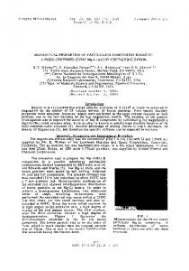
Initially we studied the effect of synthesis conditions on the electrochromic properties of the PPYDBS films. The potentiostatic method did not provide uniform films on the IT0 surface and we used the galvanostatic method at different current densities and constant charge density. This method provided more uniform films, particularly those obtained at 5.0 mA cm- *. Figure 1 shows the absorption spectra of a film prepared at 5.0 mA cm- 2 and polarized at 0.90, 0.50, 0.0 and - 0.75 V (see) in a KC1 solution. The spectral variations do not differ from previously published results and is better explained by the polaron and bipolarons model[2]. In the reduced form (-0.75 V) one observes an absorption near to 350nm which is
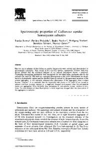
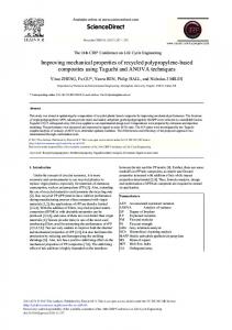
assigned to a transition from the valence to the conduction band. When the polymer is oxidized (O.OV), polaron states are formed in the gap, as evidenced by absorptions at lower energy, namely 520nm. At higher doping states (0.5V), bipolaronic levels are formed as can be seen by the growth of the absorptions above 700nm. At this stage we observe that the absorption at 520nm is present, although an intensity decrease was predicted. At the over-oxidation state (l.OOV) we see that more polaronic states are created (520nm). This behavior can be caused by the planar structure of the doping agent, which leads to planarity of pyrrole rings avoiding their relaxation. It is known that planar dopants drives the planarity of the rings[17]. The higher absorbance difference between the fully reduced and fully oxidized states occurs above 700 nm. In Fig. 2 we show the CV (-0.75 to 0.55V) together with the transmittance variation at 500, 600 and 700nm for a film obtained at 0.5mAcmw2. The voltammetry shows a broad anodic and a sharp cathodic peak. They are centered at - 0.05 V with a peak separation of 0.12 V. The hysteresis of the voltammetric curve is also present in the transmittance x potential curves (%T x E). This effect is less pronounced at 7OOnm, and it means that the relaxation process involved in the bipolaronic states are more favorable. By changing the synthesis current density we see a similar behavior, as shown in Figs 3 and 4 for films prepared at 1.0 and 5.0mA cme2, respectively. In Fig. 3 one observes a peak centered at -0.05 V with a pronounced hysteresis effect in the % T x E curves. Other interesting features are: (i) hysteresis sense which changes from the 500 to the 600nm curve; and (ii) the transmittance extremes, which are not coincident with the cathodic and anodic potential limits. The same characteristics are observed for the film prepared at 5.0mA cmd2, Fig. 4. However, E, is shifted from -0.05 to -0.13 V and the cathodic peak is better defined. By observing the cyclic voltammetry presented in Fig. 4, another anodic peak above 0.55V becomes evident. Repeating the experiment in an extended potential range, Fig. 5, a shoulder is evident at
:
f
m
a
O.lO-
5:
z
‘\
“L. ..-_._ 0.02
1
350 400
450
500
550
600
WAVELENGTH
650
700
750
000
E
/nm
Fig. 1. Absorption spectra of a PPYDBS film polarized at different potentials: (-) 0.55; (---) 0.00 and (-.-.-) -0.75 (vs. see).
1.00; (- X - X -)
’
1
-0.50
I
0.55
0.75
0.75
I
POTENTIAL
51
65
/
0.55
I
V
600 nm
I
/V
56-
0.25
1
0.75
0.50
0.55
Fig. 2. (a) Cyclic voltammetry from -0.75 to 0.55 V (vs. see, v’ = 5OmV s- ‘) and (b) %T x E curves in aqueous KCl for a film grown at 0.5 mA cm-‘.
1
I
’
79
I
0.0
POTENTIAL
-0.25
n
-0.75
1,
-0.6 -
4 . ._
‘E
tu
._
E \
a
5
Y
-0.75
I
-0.35 -
0.0 -
I
-0.50
1
1
/
V
600 nm
0.0
POTENTIAL
loo{
POTENTIAL
-0.25
I
/V
0.25
-0.75
1
I
0.50
0.55
c
Fig. 3. (a) Cyclic voltammetry from -0.75 to 0.55 V (vs. see, v = SOmVs-I) and (b) % T x E curves in aqueous KCl for a iilm grown at 1.0 mA crnef.
(a)
3
44,
58
72
86,
I
1
-44 -0.75
0
t
I
0.55
500nm
56
72
66
I
0.55
POTENTIAL
-44 -0.75
600nm
I
56
72
66
I
1.
\
L
0.55
\
0.50
700nm
-1-0.75
0.25
/ V
POTENTIAL/V
0.0
Fig. 4. (a) Cyclic voltammetry from -0.75 to 0.55 V (vs. see, v = SOmVs-‘) and (b) % T x E curves in aqueous KC1 for a tilm grown at 5.0 mA cm-‘.
E
2
2
E
w‘ y
s
09
I
-0.75 -0.50 -0.25
-0.75
16+-
-0.75
0.6
1.00
-0.50-0.25
0.25
600nm
0.50
7oio
50
go-
\
0.75
\
700nm
1.00
\
I.
POTENTIAL/V
37-0175 3o0175
65-
i
POTENTIAL/V
0.0
Fig. 5. (a) Cyclic voltammetry from - 0.75 to 1.00 V (vs. see, v = 50 mV s- ‘) and (b) % T x E curves in aqueous KCl for a film grown at 5.0 mA cm-*.
r-
(4
(a)
873
Properties of doped poly(pyrrole)
0.90 V. This second oxidation step produces a further darkening of the film as observed in the curve where the transmittance changes are more pronounced. The presence of a second anodic peak has been previously reported for PPY prepared in the presence of dodecylsulfate anion[ 151. This was discussed in terms of retention of the large surfactant anion in the polymer during the reduction process with concomitant cation insertion. In that case the anion insertion occurs when the polymer is over-oxidized at potentials higher than O.OV. This hypothesis was confirmed by electrogravimetric experiments using different aqueous electrolytes[ 181. This overoxidation has also been interpreted as a capacitive effect, and according to the model proposed by Heinze et aI.[19] it is caused by relaxation processes of the polymer. In our case the CV curve also shows the insertion of anion caused by the over-oxidation, but the relaxation process can be seen in the transmittance curves. The less pronounced hysteresis observed at 500nm suggests that the localization of double bonds is less favored. If there is a relaxation process, it must be influenced by the hydration radius of the ions that diffuse into the polymeric matrix. In order to test this hypothesis we studied the sweeping of a film prepared at 5.0mAcm-* in aqueous l.OM NaCl and LiCl solution. The results for NaCl are shown in Fig. 6. We observe a very broad anodic wave together (4
0.3
with two well defined cathodic peaks. The % transmittance curve shows a shoulder in the oxidized (dark) region which can be assigned to the insertion of the anions in the polymer matrix. The hysteresis is also different from the experiment in KCl. The results obtained for LiCl are shown in Fig. 7. In this case we also observe a broad anodic wave. However, only one cathodic wave with a shoulder is observed. These experiments provide evidences for the cation effect, which is clearer in the transmittance variation curves (Figs 5-7), where a loop is observed for LiCl in the hysteresis curves. In this work we observe that the cation of the electrolyte affects the electrochromic behavior of the PPYDBS film. Assuming that the redox process involves the relaxation of the polymeric network, the hydration radius of the cation might influence this process. This means that the electrochromic properties of conductive polymer films are not only associated to electronic effects but also to the diffusion effects associated with the electrolyte. In a previous work we have shown that the film thickness plays an important role in the kinetics of the redox process of PPYDBSCZO]. In order to study this parameter, two films were grown at different current densities, for the time necessary to reach a transmittance (at 700nm) of 40% (as described in case (b) of experimental part). The voltammetric and %T x E curves for these films are shown in Fig. 8.
-I
-0.5-
I -0.75
-0.50-0.25
I
I
0.0
0.25
m
I 0.50
0.75
1.00
POTENTIAL/V 4 700nm ,oo * 600nm
100
66
\ \
72
44 Ii -0.75 POTENTIAL
1.00
/V
Fig. 6. (a) Cyclic voltammetry from -0.75 to l.OOV (vs. see, v = 5OmVs-‘) and (b) %T x E curves in aqueous NaCl for a film grown at S.OmAcm-‘.
I
b-4
hl
0.50
-
0.25
-
‘5
0.0 -
< E . ._
-0.25-
-0.50-
t
,
1
I
1
-0.8-0.6-0.4-0.2
0.0
I
0.2
,
c
1
0.4
0.6
0.8
IlO
POTENTIAL/V
(b)
90- t
79
700 nm
600nm
-0.75 POTENTIAL Fig. 7. (a) Cyclic voltammetry
1.00
/ V and (b) ST
from -0.75 to l.OOV (vs. see, Y = 50mV s-t) aqueous LiCl for a film grown at 5.0 mA cm-‘.
x E curves in
A 0.24 0.40.3rJ, 0.20 O.la o*s -O,j_
0.1 -
6) YE /
_______
-----_-_:I” __--
o-
: E -O.l\ ._
dr:::____----/
-0.2-0.3-0.4-
b)
-0.2-
p
-0.90
-0.60-0.30
0 0.30 0.60 POTENTIAL/V
-0.34
0.90
,
,
(
-0.9-060.3
,
(
0
0.3
,
,
0.6 0.9
POTENTIAL/V s
90
ii%_
F a
30-0.9-06-0.3
, 0
1 I I_ 0.3 0.6 0.9
-0.9-0.6-0.3
POTENTIAL/V
0
0.3
0.6
0.9
POTENTIAL/V
Fig. 8. Cyclic voltammetry from -0.9 to l.OOV (vs. see, v = 50mV s-t) and %uT x E curves in KCI l.OM for two films grown at: (a) 1.0; and(b) 5.0mAcmW2. 1 = 7OOnm, (-) 1st and (---) 10th cycle. R74
Properties of doped poly(pyrrole)
We observe that the film prepared at a lower current density loses its electrochromic properties faster than that grown at higher current density. This result shows that the current density also influences the electrochromic behavior of the film. From these results we choose the synthesis at KOmAcm-’ as the best condition to study the electrochromic stability and cyclability of PPYDBS films. This was carried out by the spectrochronoamperometric technic monitoring the transmittance change at a fixed wavelength. Films were prepared at two different charge densities: 25 and 50mCcm-2. In Fig. 9 we show the chronoamperogram and transmittance change for these films. It can be seen that the thicker film has a better contrast, but it loses its electrochromic properties during cycling. This suggests a degradation of these properties by an irreversible oxidation, as indicated by the darkness of the film. In this experiment we can calculate the electrochromic efficiency (q) at 700nm. This parameter is used to characterize the electrochromic properties of a material. For the film grown at 25 mCcmm2 we obtain an efficiency of 50cm2 C- ’ for both processes. For the film prepared at 50mCcm-2 we calculated 150 cm2 C- 1 for the first cycle and 7Ocm’ C- ’ for the last cycle. Again, the loss of electrochromic properties could be detectable. These valors are low in comparison to WO, which has an electrochromic efficiency of 140 cm2 C- ’ at 630 nm.
875
The electrochromic stability was studied by chronoamperometry using a film prepared at 5.0mAcm-’ and 25mCcmv2. The film was previously activated by voltammetry and potential steps of 0.40 and -0.6OV (see) were applied at time intervals of 10s with simultaneous measurement of the current and transmittance at 600nm. In Fig. 10 we observe a faster decrease of the anodic current in relation to the cathodic current as a function of cycles. This indicates a partially irreversible oxidation process, as previously mentioned. The same behavior can be seen in the transmittance variation curves. At the beginning we have a change from 80 to 55% and after 200 cycles it decays from 70 to 55%. There is a darkening of the film up to 900 potential steps with a subsequent bleaching in the reduced state. Other parameters are important to characterize an electrochromic material. During this work, we observed that the PPYDBS film has a short optic memory. Under open circuit, in the reduced state, the film do not maintain its color, passing rapidly from yellow to blue.
CONCLUSIONS The results described in this work indicate that the electrochromic properties of poly(pyrrole) depend very much on the synthesis conditions and on the
0.4-
ht
‘5 $ N ._
O-0.4. -0.8
-
-1.61 (lb,
-2.0 0 1020 0 IO 20
-t/s 180
-
180
200
t/s
200
lOOrb TIME/r a) Fig. 9. Chronoamperograms
TIME/r
b) and %T x time for two films grown at: (a) 25; and (b) 50mCcm-2. t = 7OOnm, (-) 1st and (---) 10th cycle.
876
R. C. D. PERES et a[.
b-
0.25
/
r’ 5.0
I.1
2
TIME /h (b)
30
4-v 0.25
1.1
5.0
20
TIME/h Fig. 10. Electrochromic
stability:
(a) current
x time; and (b) %T x time. Numbers
in parentheses rep-
resent the cycle number. electrolyte. The synthesis current density effect is a consequence of the morphological and structural changes induced by the different kinetics of polymer film formation. The hysteresis effect observed in the transmittance variation curves in the voltammetry experiments can be assigned to relaxation of the polymer network when it is oxidized and reduced. The redox process involves insertion and deinsertion of the ions present in the electrolyte solution, thus these relaxation processes are also affected by the hydrated ions diffusion into the matrix, as was observed for the three electrolytes. The electrochemical stability observed for PPYDBS is low in comparison to metal oxides. This can be caused by the loss of electrochemical sites due to an irreversible oxidation of the polymer or by loss of adhesiveness of the film in relation to the IT0 electrode. Acknowledgements-R. C. D. P. thanks a fellowship from CNPq/RHAE Program, M. A. P. financial support from FAPESP (Proc. No. 91/2561-9), CNPq and, eventually, FINEP.
REFERENCES 1. T. A. Skotheim (Editor) Handbook of Conductive Polymew. Marcel Dekker, New York (1986). 2. J. L. Bredas and G. Street, Act. Chem. Res. 18, 309 (1985).
3. E. Genies, G. Bidan and A. F. Diaz, J. electroanal. Chem. 149, 101 (1983). 4. S. Kuwubata, H. Yoneyama, H. Tamamura, Bull. Chem. Sot. Jpn. 57,2247 (1984). 5. J. M. Pernaut and E. Genies, J. electroonal. Chem. 191, 111 (1985). 6. G. Zotti and G. Schiavon, Synch. Met. 30, 151 (1989). 7. Y. Tesuka. K. Aoki and K. Shinozadi. Svnth. Met. 30. 369 (1989): 8. Cs. Visy, J. Lukkari, T. Pajunen and J. Kankare, Synth. Met. 33, 289 ( 1989). 9. Cs. Visy, J. Lukkari, T. Pajunen and J. Kankare, Synth. Met. 39, 6 1 ( 1990). 10. M. Satoh, K. Kaneto, and K. Yoshino, Synth. Met. 14, 289 (1986). 11. L. F. Warren and D. P. Anderson, J. electrochem. Sot. 134, 101 (1987). 12. W. Wemet, M. Monkenbusch and G. Wegner, Mokromol. Chem. Rapid Commun. 5, 157 (1984). 13. R. C. D. Peres, J. M. Pemaut aad M.-A. De Paoli, J. Polym. Sci., Polym. Chem. Ed. 29,225 (1991). 14. J. M. Pernaut, R. C. D. Peres, V. F. Juliano, M.-A. De Paoli, J. e/ectroanaL Chem. 274, 225 (1989). 15. M.-A. de Paoli, S. Panero, P. Prosperi and B. Scrosati, Electrochim. Acta 35, 1145 (1990). 16. M.-A. De Paoli, S. Panero, S. Passerini and B. Scrosati, Adu. Mater. 2,480 (1990). 17. G. R. Mitchell, F. J. Davis and C. H. Legge, Synth. Met. 26, 247 (1988). 18. R. C. D. Peres. M.-A. De Paoli and R. Torresi, Synth. Met. 48, 259 (1492). 19. J. Heinze, M. Stiirzbach and J. Mortensen, Ber. Bunsenges. Phys. Chem. 91,960 ( 1987). 20. R. C. D. Peres, M.-A. De Paoli, S. Panero and B. Scrosati, Electrochim. Acta 37, 1173 (1992).