ELECTROMAGNETIC INTERFERENCE BY HIGH POWER MICROWAVES. G. Venugopala Rao, Amitava Roy, A. S. Paithankar and P. H. Ron. Accelerator and ...
ELECTROMAGNETIC INTERFERENCE BY HIGH POWER MICROWAVES G. Venugopala Rao, Amitava Roy, A. S. Paithankar and P. H. Ron Accelerator and Pulse Power Division Bhabha Atomic Research Centre, Mumbai- 400 085 ABSTRACT- High Power Microwave (HPM) radiation with frequency > 1GHz may penetrate the electronic systems through front or backdoor openings and propagate like the genuine signal. Some times parasitic resonance may amplify the HPM signal and cause havoc t o the systems. The surface currents caused by HPM can also interfere with the normal signals and upset the functioning of the devices. The HPM incident upon the electronic components may damage them by the following mechanisms like adiabatic heating of the junction or punch-through of the depletion layer. High Power Microwave radiation generation studies were performed using the intense electron beam from the KALI1000 Pulse Accelerator by Virtual Cathode Oscillator method. Various axial resonant cavities were used to optimise the microwave emission. The maximum power of 500MW around 5GHZ was generated by using a axial resonant cavity with a resonant frequency of 5GHz. The HPM was also used to study the effects on some electronic devices. The HPM caused damage to the op-amps and stopped the functioning of the personal computers. The HPM can also cause breakdown in the lowpressure devices like hydrogen thyratrons and cause spurious triggering in the control circuits that use them.
be raised above 600°K, for the damage of the semiconductor devices. If the timescale is short compared to thermal diffusion times(c1OOns), the temperature increases rapidly in proportion to the deposited energy. For pulses greater than 1OOns, thermal diffusion carries energy away from the junction. Thus short pulses (loons) with low peak power. If the microwave energy is below the damage threshold, it may get rectified at p-n junction and travel like a normal signal and cause temporary upset or disruption to the circuits. In our laboratory High Power Microwave(HPM) generation studies were carried out using the Intense Electron Beam available from KALI-1000 Pulse Accelerator by using the Virtual Cathode Oscillator(VIRCAT0R) method. The HPM generated was also used to demonstrate the effects on some electronic components/devices. The details are given in the following sections.
m
1. Introduction
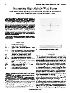
The typical Electromagnetic Pulse from a High Power Microwave Source is shown in Fig 1. The duration of the pulse may be ranging from 10 nanoseconds to 100s of nanoseconds with the sub-pulse duration less than a nanosecond. The HPM pulse can couple to the systems[l,2] by the front door path, which is normally intended for microwave transmission and reception or by the backdoor paths like windows, doors, connectors and cable shields. It was observed that microwave energy coupled to the cables is highest at frequencies of 1-2GHz. The coupling to the bare wires is about lo4 times to that of the standard coaxial cable. When the microwave energy coupled- to the components is high it may damage the components by raising the temperature at p-n junction or cause punch-through in the multiple p-n junctions. The temperature of the junctions is to
20
Fig. 1. Schematic of a typical Electromagnetic pulse from a HPM source 2. Generation of HPM by VIRCATOR method
VIRCATOR method[3] is generally used to produce radiation with broadband output, that can couple to a wide variety of devices. In this method an intense electron beam generated from a Pulse Accelerator is injected in to a vacuum chamber. A Virtual cathode forms, when the injected current is greater than the space charge limiting current, I, given by
Proceedings of INCEMIC 2001 - 2002
where rb is the beam radius and R is the drift column radius, is the relativistic factor, and e and m, are electron charge and rest mass respectively. The virtual cathode reflects the electrons that follow the beam front. Thus electrons oscillate between the cathode and virtual cathode and cause microwave emission. The reflexing frequency is given by
f,
=v 4d
where v is the velocity of the electrons. The virtual cathode also emits radiation around the beam plasma frequency. The frequency at which maximum power emitted is given by I12
f,, =lO.O[&)
4. Axial Vircator (3)
where J is the current density expressed in kNcm'. Both mechanisms mentioned above produce radiation at nearly same frequency and the emission is broadband. Using a resonant structure in the down stream would reduce the bandwidth of the emitted radiation. 3. KALI-1000 Pulse Accelerator
The KALI-1000 Pulse Accelerator (Fig.2) was designed and developed indigenously at Accelerator and Pulse Power Division of BARC[4]. It uses a Radial Transformer[5], a Water Transmission Line and a Gas Spark Gap to generate the desired high voltage pulse. The Radial Transformer has a single turn primary and 60 turn secondary windings. The 1.3m long coaxial Transmission Line uses demineralised water as dielectric and has 4nF capacitance. The Spark Gap contains two electrodes of Rogowski profile separated by 2cm and 'uses SF6 gas at pressure of . 2.0kg/cm2 in a cylindrical chamber of diameter 25cm and length 30cm.
Fig. 2 Schematic Accelerator.
of
the
A vacuum Field Emission Diode was used to generate the Intense Electron Beam. The dimensions of the cathode diameter and the A-K gap were chosen so that the diode impedance matches to that of the pulse power system. A graphite cathode(K) of diameter 7cm and a mesh anode(A) of diameter 24cm separated by an optimum gap of 0.75cm were selected for the diode. A resistive(CuS04) Voltage Divider(VD) and a self-integrating Rogowski Coil( RC) were used to measure the diode voltage and current respectively. The high voltage pulse generated from the pulse power system was applied to the field emission diode with the vacuum of ~ . O X ~ O - ~ mbar and the intense electron beam with the parameters of 250keV, 15kA and lOOns was generated.
KALI-1000 Pulse
Proceedingsof INCEMIC 2001 - 2002
The Intense Electron Beam was injected into the Vircator Chamber of diameter 25cm and length 25cm to generate the HPM. The Vircator region was also maintained at a pressure of ~ . O X ~ O - ~ mbar. The HPM output is taken from a window of diameter 25cm mounted at the end of the chamber. The space charge limiting current in the configuration used in the present experiments is around 1.OkA. The estimated reflexing and virtual cathode oscillating frequencies are around 7 GHz and 5 GHz respectively in our experiment.
D-R
U
U
Fig. 3. Scematic of the HPM diagnostic setup. The microwave power density was measured by using the set up shown in Fig. 3. The HPM radiation was received by a double-ridge horn antenna(D-R) located 3.25m away from the output window and after suitable attenuation (50dB) given to a diode detector(DD) by using a Cable. The range of the emitted frequencies was determined by using various combinations of low pass filters ahead of the detector. It was found that the frequency of emission is between 3 GHz and 7 GHz. The local power density Pd is given by
where S, is the power received by the detector, X, attenuation used and G the gain of the receiving antenna at the operating wavelength h. The measured power density at 3.25m is 80MW/m2 at 5GHz, the central frequency of the
21
emission. The corresponding electric field strength at this location is l7OkV/m. The HPM from this Vircator device was used to illuminate the electronic devices and the results are presented in section 6.
5. Axial Resonant Vircator A coaxial resonant structure (Fig. 4) with 15cm inner diameter 25cm length was used as the vircator chamber. The output circular waveguide has an inner diameter of 6.6cm and length 30cm. The resonant frequency of the structure is 5GHz and the cut off frequency of the output waveguide is 3.5GHz. The calculated unloaded Q-Value is 40000. The cathodes with diameter 7cm, 9.5cm and 11.5cm diameter were used in the field emission diode. The typical microwave detector signal is shown in Fig. 4. The maximum microwave power was observed for the cathode with 11.5cm dia for which the reflex frequency of the Vircator(4GHz) was close to the cavity resonance frequency. The estimated peak microwave power for this geometry is 500MW.
some of the shots it was observed the set-up details were also changed, so that the personal computer cannot be restarted easily. Two working amplifier circuits that use 741 opamp and OPA37GZ(BurBrown) low noise low drift opamp were kept near the output window of the system(where the E-field is greater than 170kV/m). The precision OPA37GZ opamp was found damaged due to the punch-through effect or interconnection failure and the less precision 741opamp was also found to malfunction after exposing for one shot of the HPM from the KALI1000 Pulse Accelerator. A thyratron circuit, that is generally used for switching the pulse systems or radars was selected for the HPM illumination. The circuit uses a hydrogen thyratron (EEV FX 2505) and generates 2kV, Ips pulse at the output when the Anode is maintained at a voltage of 1.6kV a’nd the grid is given a pulse of 200V. The circuit was placed near the system 50cm from the output window and when illuminated with the HPM from KALI-1000 Pulse Accelerator, gas breakdown occurred in the thyratron tube and the circuit generated the output voltage pulse (without applying any voltage to the grid of the thyratron). This indicates the HPM can induce a spurious trigger in the power electronic circuits that use devices like thyratrons. Acknowledgments
Fig. 4 Schematic of the Axial Resonant Vircator
The authors are thankful to Dr. V. C. Sahni, Director, Physics Group, Dr. R. C. Sethi, Head, APPD, Dr. K. C. Mittal and Dr. K. V. Nagesh for the encouraging discussions. REFERENCES
[I] C. D. Taylor and D. V. Giri, “High Power
Fig. 5 Typical signal from the Diode Detector Scales: 200mV/div and 2Ons/div 6. HPM Effects on electronic components
A working personal computer was located at 3.25m from the output window (where the measured E-field is 170kV/m). When the HPM pulse from the KALI-1000 pulse Accelerator was applied, it caused divide overflow errors in the computer and the computer stopped working. Computer monitor colours also got changed. In
22
Microwave Systems and Effects”, Taylor and Francis Bristol, PA, 1994. [2] C. D. Taylor and N. H. Younan, “Effects from High Power Microwave Illumination” Microwave Journal-June 1992. [3] L. E. Thode, “Virtual Cathode Microwave Device Research: Experiment and simulation“ in High Power Microwave Sources ed V. L. Granatstein and I. Alexeff Norwood, Mass. Artech House 1987. [4] P.H. Ron, “Configurations of Intense Pulse Power Systems for generation of Intense Electromagnetic Pulses” INCEMIC-99, New Delhi 1999 India. [5] K. V. Nagesh, P. H. Ron and V. K. Rohatgi “Radial Transformer for KALI-1000 in Beams and Plasmas applications in Materials Technology BARC 1990.
Proceedings of INCEMIC 2001 - 2002