Available online at www.sciencedirect.com
Procedia CIRP 6 (2013) 600 – 604
The Seventeenth CIRP Conference on Electro Physical and Chemical Machining (ISEM)
Electromagnetic jigsaw: metal-cutting by combining electromagnetic and mechanical Forces P. Kumar1, A. Mishra2, T. Watt3, I. Dutta2,*, D. L. Bourell3, U. Sahaym2 1 Department of Materials Engineering, Indian Institute of Sciences, Bangalore 560012, India School of Mechanical and Materials Engineering, Washington State University, Pullman WA 99164, USA 3 Department of Mechanical Engineering, University of Texas at Austin, TX 78712, USA * Corresponding author. Tel.: 1-509-335-8354; fax: 1-509-335-4662.E-mail address:
[email protected]. 2
Abstract The magnetic saw effect, induced by the Lorentz force generated due to the application of a series of electromagnetic (EM) pulses, can be utilized to cut a metallic component containing a pre-existing cut or crack. By combining a mechanical force with the Lorentz force, the cut can be propagated along any arbitrary direction in a controlled fashion, thus producing an 'electromagnetic jigsaw', yielding a novel tool-less, free-formed manufacturing process, particularly suitable for hard-to-cut metals. This paper presents validation of the above concept based on a simple analytical model, along with experiments on two materials - Pb foil and steel plate. © 2013 The Authors. Published by Elsevier B.V. Open access under CC BY-NC-ND license. © 2013 The Authors. Published by Elsevier B.V. Selection and/or peer-review under responsibility of Professor Bert Lauwers Selection and/or peer-review under responsibility of Professor Bert Lauwers Keywords: Lorentz force; Magnetic saw effect.
1. Introduction The ability to cut complicated shapes and designs in metallic plates, sheets, foils, thin films and coatings without the use of cutting tools can be a significant advantage in a wide range of applications. For instance, in the meso- and micro-systems industry (e.g., MEMS and electronic packages), where laser cutting is often utilized to cut patterned metal film components attached to plastic substrates, this process would proffer the capability to do so without laser-induced damage to the substrate. There are a plethora of potential applications for free-form cutting of meso-scaled parts [1,2], including cardiovascular and diagnostic devices, clot removal catheters, camera parts, wireless devices, microfluidic systems, fiber optic components, micromolds, etc. In this paper, we present evidence of the ability to cut metal in a non-contact fashion, using a series of electric pulses, and discuss the primary parameters that play a role in determining the quality of the cut. A metal-cutting approach based on electrical pulses could be highly attractive for machining of
complicated shapes from hard, brittle metal components for the transportation and construction industries, where tool wear is a significant problem. Electromagnetically induced extension of surface defects (cracks) is frequently observed in electromagnetic launchers (i.e., railguns), where both the rail and armature are subject to fracture due to the extreme electromagnetic load imposed by the passage of a large current pulse (~106 A over 5 milliseconds). During a launch, when an electric pulse is passed through the rail, the current is initially confined to a 50200µm thick skin on the rail surface, and upon encountering a surface crack (defect), changes direction as it makes its way around the crack tip, as shown schematically in Figure 1a. Together with the imposed magnetic field (B), the skin current density (J) creates a Lorentz force (F = J x B), leading to substantial Mode I loading of the crack faces, and resultant extension of the crack due to the ‘magnetic saw effect’ [3-6]. In addition to the rail, evidence of the magnetic saw effect has also been observed in armatures [6]. Coupled to this crack driving force (due to the Lorentz force), extreme Joule
2212-8271 © 2013 The Authors. Published by Elsevier B.V. Open access under CC BY-NC-ND license. Selection and/or peer-review under responsibility of Professor Bert Lauwers doi:10.1016/j.procir.2013.03.080
P. Kumar et al. / Procedia CIRP 6 (2013) 600 – 604
heating of the crack-tip can cause localized melting, assisting crack extension [4, 7]. An example of this is shown in Figure 1b, where the liquefied zone produced at the crack tip due to current crowding [7] is separated by the Lorentz force acting perpendicular to the crack, leading to crack extension during the passage of the current pulse. Although the Lorentz force across an existing crack can place the crack tip in Mode I loading, if a far-field force is also applied mechanically to the component at an angle θ (≠ 90°) to the crack length, it is possible to place the crack tip in mixed-mode loading, and make the crack change direction (as shown schematically in Figure 2). This suggests a mechanism by which an existing starter crack in a metallic material may be propagated and turned by a combination of electromagnetic cum mechanical loading, lending itself to the ability to cut a metal along any given path.
δskin
surface flaw
I
r j
(current)
I
r F
2.1 The Skin Effect and Current Crowding
r B
(a)
(b) Fig. 1. (a) Schematic illustration of current flowing through a skin (thickness=δskin) along the surface of a conductor due to the application of a brief pulse, and upon encountering a surface crack (defect), changing direction as it makes its way around the crack tip. Small arrows represent current density (j) vectors. (b) Example of magnetic saw effect (MSE) in a railgun armature. An existing crack extends due to the combination of Lorentz force (F) across the crack faces and localized crack-tip melting due to extreme Joule heating, produced as a result of current-crowding as the current path turns around the crack tip [13]. Arrows represent current path.
FMechanical extended & turned crack
θ FLorentz
I
Fig. 2. A mechanically applied far-field force applied at an angle θ to the crack length, in conjunction with mode I loading by the Lorentz force due to a current pulse, results in mixed-mode loading, and makes the crack change direction.
2. Conceptual Approach
In the approach taken here, a starter-crack (or preexisting micro-cut) is propagated in a metal by simultaneously applying a mechanical force and a series of electromagnetic force pulses (EMP), allowing the crack to extend as well as alter direction as required, depending on the inclination of the mechanical force to the existing crack. The applied mechanical force is much smaller than that required to cause fracture by itself. When an EMP is applied, the added Lorentz force and localized crack-tip melting induced by current crowding enable crack extension. To accomplish this, several phenomena are exploited, including the skin effect, current crowding, crack-tip melting and melt-sweeping due to Lorentz force, electromagnetically induced fracture, and traditional fracture mechanics. The principal features of these phenomena are outlined below.
When a rapidly varying current is passed through a conductor, e.g., a high frequency alternating current or a short-duration pulse, the current flows primarily through a “skin” along the free surfaces of the conductor, rather than being uniformly distributed throughout the cross section [8, 9]. The current density within this skin is therefore substantially greater than the nominal current density, the phenomenon being known as the skin effect (SE). Under conditions where the conductor is also moving at a very high velocity (e.g., railgun armatures), a velocity skin effect (VSE) further concentrates the electric current in an even thinner surface skin, elevating the surface current density further [10-12]. Under high frequency alternating current (AC), the skin depth can be even smaller, resulting in higher electrical resistance [8, 13]. Experimental observations of microstructural changes in rails and armatures in railguns suggest that the skin depth near the armature is typically on the order of ~100 µm [7]. Skin effects often lead to surface melting and nearsurface grain boundary melting of conductors, e.g., at armature-rail contacts in railguns [14-16]. The already high current density flowing through the skin becomes further concentrated due to current crowding when the current path is forced to alter direction [7, 17], e.g., for solder joints in a microelectronic package and for a railarmature contact in a railgun. Current crowding, which enhances the local current density, is known to foster crack tip melting and the magnetic saw effect in electromagnetic launchers (railguns) [7]. Such current crowding, enhanced by the skin effect due to the application of a pulsed current, is critical to localized heating and softening (or liquefaction) of the crack tip, and resultant crack propagation.
601
602
P. Kumar et al. / Procedia CIRP 6 (2013) 600 – 604
2.2 The Magnetic Saw Effect The magnetic saw effect (MSE) is a generic name for the propagation of a crack or flaw under an electromagnetic pulse, which effectively serves as a “saw” in one of three ways. First, if no crack tip melting occurs, and the Lorentz force generated across the crack tip is adequate, MSE leads to crack-tip stress-field amplification and fracture mechanics driven crack extension when a current pulse is applied. Secondly, if the crack tip is relatively sharp, causing excessive current crowding, and in turn resulting in melting, the Lorentz force acting perpendicular to the crack length can place the crack-tip liquid in tension and lead to meltseparation and re-solidification, thereby extending the crack [6,7,14]. In addition to melting, evaporation of the crack tip liquid can occur, creating a series of ‘blowholes’ due to the application of multiple pulses [3,7,14,18]. Thirdly, as the crowded current at the crack tip travels perpendicular to the crack length when moving from one crack face to another, a Lorentz force acting parallel to the crack length is developed, which pushes the liquid along the crack, allowing it to propagate [14]. Experiments on pre-cracked Al plates [3] have shown that there is a threshold current density below which crack extension does not occur. As j increases, the crack extends along a hairline, and with further increase, blow-holes and eventually, bifurcations are created. Recent experiments using fatigue pre-cracked samples suggest that under combined mechanicalelectromagnetic loading, the threshold current required to propagate the crack is smaller [18]. This is clearly advantageous for the proposed metal-cutting process in terms of avoiding blow-hole type artifacts to achieve a well-controlled kerf. This can be further aided by active cooling of the work-piece, based on our preliminary experiments, as reported below (section 4). The Lorentz force is the only crack opening agent during the initial stage of the current pulse (before melting occurs). If this force exceeds a critical crack driving force (i.e., a critical strain energy release rate G or J-integral), the crack extends, but is limited by the duration of the pulse. Therefore, initially, a crack initiation condition based on a Lorentz-cum-mechanical force induced G or J can yield the crack extension condition. Later, when both fracture and meltseparation driven MSE occur, a separate fracture criterion would be more appropriate. We will consider both as we develop the conditions for controlled crack extension.
2.3 Electromagnetic Forces around a Crack
There is considerable literature on models for the stress distribution and crack driving forces around an elliptical crack inside an infinite body due to an applied electric current [17-25]. It is known that increasing crack-tip sharpness enhances the current concentration, thereby enhancing the crack-tip stress field [19-21], as well as the strength of the magnetic field at the crack tip [30]. Recent modeling work [24, 25] has demonstrated that the application of electric current around a crack leads to excessive heating and melting near the crack tip; but it was also suggested that when the current density exceeds a threshold value, the stress intensity factor due to thermal stresses can be higher than the fracture toughness (KIc), leading to the unstable crack propagation. Most of the available work on fracture under EM loads is theoretical [e.g., 19-25], with only two recent experimental studies [10, 25]. However, the effect of superimposed mechanical and electromagnetic loads on fracture is unclear. Mechanical force fields in metals are known to generate electromagnetic fields during fracture [26]. So it stands to reason that the impact of superimposition of mechanical and EM loads during fracture will not be simply additive, but rather, be interactive. Complicating this further is the softening or liquefaction of the crack tip. Based on the above discussion, the approach adopted in this work was to exploit a combination of the skin effect, the magnetic saw effect, and the interaction of the crack-tip electromagnetic forces with the softened/liquefied crack-tip region to promote propagation of a pre-existing crack/cut. 3. Experimental A fine starter crack was cut perpendicular to the long edge of a rectangular (~5 mm x 10 mm) piece of annealed and etched 20 µm thick Pb foil. The edges of the foil were glued to a polymer substrate (HDPE). The substrate was loaded at various levels of mechanical tension using the set-up shown in Figure 3, and a 6ms current pulse (peak current varying between ~ 50-200 A) was introduced into the Pb foil close to the crack-faces, forcing the current to travel parallel to the crack. The tests were either conducted with the foil at ambient temperature, or following cooling to -25ιC or -70°C using a mixture of ethanol and liquid nitrogen. Following testing, the crack-tip regions samples were inspected in the optical microscope as well as the scanning electron microscope.
P. Kumar et al. / Procedia CIRP 6 (2013) 600 – 604
Fig. 3. Fixture employed to simultaneously apply mechanical and electromagnetic loads inclined to each other.
A second set of samples, comprising a 2 mm thick rectangular piece of high-strength steel (AISI 4340), was also subjected to a combination of mechanical tension and current pulse. The testing fixture (Figure 4) is designed to operate on a standard Mode-I/II plane-stress fracture specimen. All specimens had a pre-existing crack started with a wire electrical discharge machine (EDM), with the initial crack depth somewhere between 6.35 mm and 25.4 mm. The fixture design was an adaptation of the modified Arcan test fixture which has been used since the late 1970s for mixed-mode fracture mechanics testing [27, 28]. The bolts that are used to load the specimen also apply a compressive load which can be used to distribute the loading stresses to the specimen via friction. Following these experiments, the sample was inspected in an optical microscope.
blow-holes, crack-tip bifurcation, and general melting and loss of definition of the crack front. In the samples cooled to -25°C, uncontrolled melting/evaporation, which precluded clean, controlled crack extension, was avoided. Under these conditions, the crack extended in a controlled fashion, with a kerf-width no larger than that of the original crack. In the experiments conducted under a combination of electric pulsing and mixed-mode loading of Pb-foils on HDPE substrates, the mechanical load inclined to the pre-existing crack was observed to re-orient the crack in a controlled way. Furthermore, cooling the sample to 70°C makes the kerf width of the re-oriented crack much smaller than that of the starter crack (Figure 5), suggesting that the crack kerf can be controlled with precision under optimal conditions.
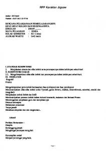
Fig. 5. Alteration of starter crack direction in a Pb foil due to 3 pulses of 200 J, tension of ~3 N at 30° to the crack-normal, and sample temperature of -70°C. Arrows indicate mechanical loading direction.
Fig. 6. A high-strength steel plate loaded mechanically and electromagnetically to propagate the crack at ~22.5° to the original crack direction.
Fig. 4. Loading fixture in load frame (total weight = 25.45 kg), with sample mounted.
4. Results In the Pb-foil experiments, crack extension was only observed above a nominal current density of 3.7 x 10⁴ A/cm2, albeit with very different crack-front morphologies, which included the formation of large
Figure 6 shows a hardened high C steel plate with a starter crack subjected to a series of EM pulses, and an applied tensile load acting at 45° to the crack. Following pulsing, the crack propagated at an inclination of approximately 22.5° to the crack. This is because the direction of the resultant force lies between the Lorentz force (which acts perpendicular to the crack at any given instant) and the applied tension (which acts at 45° to the crack). Results of simple calculations suggest that around a peak current of 60-80 A, the Lorentz and
603
604
P. Kumar et al. / Procedia CIRP 6 (2013) 600 – 604
mechanical forces are similar in magnitude. Therefore, the resultant force acts at roughly ~67.5° to the crack, and this results in the crack turning away from the starter-crack direction by ~22.5°. This clearly demonstrates that a combination of EM and inclined mechanical loading can be utilized to extend the crack along a predictable direction.
10. 11. 12.
13. 14.
4. Summary 15.
It has been demonstrated that metallic materials can be cut in a non-contact, free-form fashion by the simultaneous application of electromagnetic and mechanical loading. The electromagnetic load, applied through a series of current pulses across a pre-existing or pilot crack, always acts normal to the crack direction. In order to alter the crack direction, the direction of the mechanical force (tension) has to be continually adjusted. The combination of a number of phenomena leads to crack extension. This includes the skin effect due to a rapid current pulse, the magnetic saw effect, and the interaction of the crack-tip force field with crack-tip liquefaction or softening. Ongoing work is addressing the optimization of these conditions to produce controlled crack extension.
16.
17.
18.
19.
20.
21.
Acknowledgements This work was supported by the National Science Foundation under grants CMMI-1103199 and CMMI1232668. The authors gratefully acknowledge the assistance of Drs. Francis Stefani and Alex Sitzman with the experiments on the steel samples. References 1.
2.
3.
4.
5.
6.
7.
8. 9.
“Electromagnetic Manufacturing: It’s a knockout”, The Economist, Jan. 16, 2010, p. 80; “Electromagnetic Fields as Cutting Tools”, Science Daily, Dec. 10, 2009. K.F. Ehmann, et al., “Micromanufacturing: International Research and Development”, Springer, Dordrecht, The Netherlands, (2007), pp. 2-3. S. Satapathy, F. Stefani and A. Saenz, "Crack Tip Behavior Under Pulsed Electromagnetic Loading", IEEE Trans. on Magnetics, 41, 2005, pp. 226-230. G. Yagawa and T. Horie, "Cracked Beam under Influence of Dynamic Electromagnetic Force", Nuclear Eng. and Design, 69, 1982, pp. 49-52. V. M. Finket, Y. I. Golovin and A.A. Sletkov, "Disintegration of a Crack Tip with a Strong Electromagnetic Field", Sov. Phys. Dokl, 1977, p. 22:11. T. E. James, “Current Wave and Magnetic Saw Effect Phenomena in Solid Armatures”, IEEE Trans. Magnetics, 31, 10095, 622-627. T. Chen, X. Long, I. Dutta and C. Persad, “Effect of Current Crowding on Microstructural Evolution at Rail-Armature Contacts in Railguns”, IEEE Trans. Magnetics, 43, 2007, pp. 3278-3286. J D Cockcroft, “Skin effect in rectangular conductors at high frequencies”, Proc R Soc, 122 (1929) 533. G. C. Long, “Railgun current density distribution”, IEEE Trans Magnetics 22(1986) 1597.
22.
23.
24.
25.
26. 27.
28.
G C Long and W F Weldon, “Limits to the velocity of solid armatures in railguns”, IEEE Trans Magnetics, 25 (1989) 347 L E Thurmond, B K Ahrens and J P Barber, “Measurement of the velocity skin effect”, IEEE Trans Magnetics 27 (1991) 326 K T Hsieh, F Stefani and S J Levinson, “Numerical modeling of the velocity skin effects: an investigation of issues affecting accuracy”, IEEE Trans Magnetics 37 (2001) 416 J D Cockcroft, “Skin effect in rectangular conductors at high frequencies”, Proc R Soc, 122 (1929) 533 D Melton, T Watt and M Crawford, “A Study of Magnetic Sawing in an Aluminum Bar”, IEEE Trans on Magnetics, 43 (2007) 170. A Yeoh, G Prabhu and C Persad, “Liquation cracking and its effects in aluminum alloy armatures”, IEEE Trans on Magnetics 33(1997) 419. T J Watt and M D Bryant, “Cracking and dominant stresses in the throat region of C-shaped solid armatures”, IEEE Trans on Mangentics 43(2007) 418. Y.H. Lin, Y.C. Hu, C.M. Tsai, C.R. Kao and K.N. Tu, "In situ observation of the void formation and propagation mechanism in solder joints under current-stressing", Acta Mater., 53, 2005, pp. 2029-2035. F Gallo, S Satapathy and K Ravichandar, “Melting and Cavity Growth in the Vicinity of Crack Tips Subjected to ShortDuration Current Pulses”, IEEE Trans on Magnetics, 45 (2009) 584. G Yagawa and T Horie, “Cracked beam under influence of dynamic electromagnetic force”, Nucl Engng Design, 69(1982) 49. G Yagawa and S Yoshimura, “Dynamic fracture mechanics with electromagnetic force and its application to fracture toughness testing” Engng Fracture Mech, 23 (1986) 265. G. Yagawa, S. Yoshimura and Y. Akahoshi, “Dynamic fracture mechanics under electromagnetic force”, Fusion Engng Design, 7 (1988-1989) 269. N. Hasebe, X. Jin, L. M. Keer and Q. Wang, “Electromagnetic Fields Induced by Electric Current in an Infinite Plate with an Elliptic Hole”, Quarterly journal of mechanics and applied mathematics 61(4)(2008) 615. X. Jin, N. Hasebe, L. M. Keer and Q. Wang, “A Comparative Study of Modeling the Magnetostatic Field in a CurrentCarrying Plate Containing an Elliptic Hole”, IEEE trans on magnetics_45(2009)1990. N Hasebe, C Bucher and R Heuer, “Analyses of thermal conduction and stress induced by electric current in an infinite thin plate with an elliptical hole”, J Thermal Stresses 32(2009) 1065. N Hasebe, C Bucher and R Heuer, “Heat conduction and thermal stress induced by an electric current in an infinite thin plate containing an elliptical hole with an edge crack”, Int J Solids Structures 47(2010) 138. A. Misra, “Electromagnetic Effects at Metallic Fracture”, Nature, 254, 1975, pp.133-134. M. Arcan, Z. Hashin, A. Voloshin, “A Method to Produce Uniform Plane-stress States with Applications to Fiberreinforced Materials,” Experimental Mechanics, pp. 141-146, 1978. S.R. Hosseini, N. Choupani, A.R.M. Gharabaghi, “Experimental Estimation of Mixed-Mode Fracture Properties of Steel Weld,” World Academy of Science, Engineering and Technology 41, pp. 770-775, 2008.