fyi =; Y2. "T - f.*. -- c, = Race= L a. -S2LC+I(;x2*x1) gm gm. R. S i. 1501121. Fig. 2 Design table for series arms qfladderfilters. According to the proposed design ...
Table-based linear transformation filters using OTA-C techniques Y . 3 . Hwang, S.-I. Liu, D.-S.. Wu and Y.-P. Wu
=
~
sRC
La
-=
gm Indexing terms: Active filters, Operational transconductance amplifiers, Capacitors
Linear transformation (LT) [I] active filters using operational transconductance amplifiers (OTAs) and capacitors are presented. Based on the LT, two simple and systematic design tables are given to realise OTA-C filters efticiently. Using the proposed design tables, the synthesised all-pole and elliptic filters employ minimum numbers of OTAs and only grounded capacitors. As an enample, a new third-order elliptic lowpass filter is realised. Experimental results are obtained to verify the theoretical analysis.
+E
-SZ
+
(3) 1 Its corresponding OTA-C circuit can be realised in the first row of Fig. I with the design equation Y2
RC
(4)
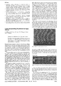
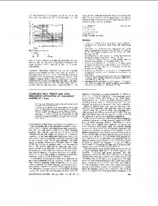
The output termination and shunt arms with all-pole and finite transmission zero sections are also established as shown in Fig. I. Here, the signs of x,and y , are determined by those of p, and y, in the transformation matrices, respectively. Fig. 2 shows the series arms, and the signs of x , and yr are determined by those of a,and 6, in transformation matrices, respectively. Note that all the OTAs are identical in Figs. I and 2. Transfornationnntrtx OTA- C circuit and transfer tinction and desian eauation
Introduction. A doubly terminated LC ladder filter has very low sensitivities, so it is suitable for monolithic integrated filters immune to unpredictable variations of process parameters. However, most proposed OTA-C synthesis methods [2-51 for emulating high-order LC ladder filters are subject to either complicated design procedures or extra numbers of OTAs. Linear transformation (LT) active filters have the advantages that we can realise every section of the original ladder prototype using active elements individually. OTAs are suitable for LT filters because they have high input impedances. Furthermore, systematic design tables can be established to simplify the design procedures. In this Letter, we present the LT design tables by which OTA-C filters can be synthesised efficiently. Moreover, our proposed filter uses not only minimum numbers of OTAs but also grounded capacitors.
;
ransformationmatrix OTA- C circuit 'Iter section and transfer functmn and design equation
fyi
a
=; Y2
--S2LC+I(;x2*x1) Si
f.*
"T c, = Race= L gm gm R
1501121 Fig. 2 Design table for series arms qfladderfilters
According to the proposed design tables, an LT active filter can be synthesised using the following procedures: First, divide the original ladder prototype into several sections and choose appropriate transformation matrices from the design tables to carry out their x-y domain transfer functions. Next, replace the transfer functions with their corresponding OTA-C circuits and connect neighbouring sections with the cross-cascade interconnection [l]. Finally, determine the values of transconductances and capacitances via the derived design equations. Moreover, if we observe the compatibility relationship [I], the same OTA-C circuits can be realised by any transformation matrix of every section of the design tables. Table 1: Comparisons between previous work and ours
Fig. 1 Design table for shunt arms of ladderfiltery
and procedure: Using LT, we can transform the inputloutput voltage and current variables of a two-port network into two new variables J, and y,. Their characteristics can be given as Design tables
where x, and y, have the dimensions of voltages. For example, the input termination (i.e. an R-C shunt arm) of a ladder filter is connected to a voltage source E, as shown in the first row of Fig. I . If we choose the transformation matrix as
[:; f;] ~
0 = [l
-R 0
]
we can obtain the output variables x2. y. and yield
ELECTRONICS LETTERS
24th November 1994
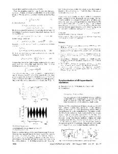
Design example and experimental result: To demonstrate the effciency and the flexibility of the proposed design tables. a thirdorder LC elliptic lowpass filter is realised. Its prototype is shown in Fig. 3a. with 1dB ripple, lOkHz bandwidth and minimum 34 dB attenuation in the stopband. First. we can divide the filter prototype into three sections and choose two groups of appropriate transformation matrices to obtain slightly different transfer functions as shown in Fig. 3u. We then replace them with the corre-
Vol. 30
No. 24
2021
sponding OTA-C circuits and join them together with the crosscascade interconnection. Fig. 3b shows the same completed circuit, suitable for any transfer function, and it employs only seven identical OTAs and grounded capacitances. The required numbers of OTAs in Fig. 36 are less than those in previous works [2- 51, and a comparison of the numbers of OTAs and capacitors used in our work and other works is shown in Table 1. Fig. 3b is experimentally verified by using the bipolar OTAs LM13600 [6] along with discrete capacitors. Here, we use the R-C pole-zero compensation, also shown in Fig. 36, to reduce the high quality factor Q of the complex pole at node A [7]. Its amplitude response is shown in Fig. 4. The deviations between the theoretical and experimental curves are specified by the input and output impedances of the LM13600.
[0-R] 1
0
,[1 0 1 1 0 , O R 0-R
3 4
S 6
I
and SANCHEZ-SINENCIO, E.: ‘Signal flow graph OTA-C integrated filters’. Proc. IEEE ISCAS, 1988, pp. 2165-2168 CALOBA, L.P., and DE QUEIROZ, A.C.M : ‘OTA-C simulation of passive filters via embedding’. Proc. IEEE ISCAS, 1989, pp. 1083-1086 CALOBA, L.P., DE QUEIROZ, A.C.M , and SANCHEZ-SINENCIO,E : ‘Signal flow graph OTA-C band-pass and band-reject integrated filters’. Proc. IEEE ISCAS, 1989, pp. 16241627 ANADA MOHAN, P.v.: ‘Novel OTA-C filter structures using grounded capacitors’. Proc. IEEE ISCAS, 1991, pp. 1347-1350 National Semiconductor Corporation, ‘Linear data book’, 1982 DE QUEIROZ, A c M., and CALOBA, L.P.: ‘Some practical problems in OTA-C filters related with parasitic capacitances’. Proc. IEEE ISCAS, 1990, pp. 2279-2282 DE QUEIROZ, A.c.M., CALOBA, L.P.,
Voltage-mode notch, lowpass and bandpass filter using current-feedbackamplifiers
]‘[O R I
j
2
1 0
C.-M. Chang, C.-S. Hwang and S.-H. Tu Indexing terms: Active filters, Current-modecircuits
A voltage-mode filter employing three current-feedback amplifiers, two grounded capacitors and three floating resistors is presented. The proposed circuit offers the following advantages: realisation of notch, lowpass and handpass signals from the same configuration, no requirements for component matching conditions, orthogonal control of W. and Q, and the use of two grounded capacitors ideal for IC implementation, and low active and passive sensitivities and cascadability.
Fig. 3 Third-order LCfilter prototy e and its transformation matrices and design equations, and correspondj)ngOTA-Cfilter derivedfrom proposed design tables a Third order LC filter 6 Corresponding OTA-C filter
-20 m U- -30 C
g-40 -
-50 -
f
-60
i
10
frequency, Hz
J1011LI
Fig. 4 Amplitude response of Fig. 3b Conclusions: Systematic and effective design tables for simulating high-order LT OTA-C filters are presented. According to these design tables, we can realise filters with minimum numbers of OTAs and grounded capacitors. It is a powerful method for realising high-order filters. 0 IEE 1994 Electronics Letters Online No: 19941318
9 September 1994
Y.3. Hwang, S:I. Liu, D.4. Wu and Y.-P. Wu (Department of Electrical Engineering, National Taiwan University, Taipei, Taiwan 10664, Republic of China)
References 1
and CONSTANTIMDES. A.G.: ‘Linear transformation active filters’, IEEE Tram., 1978, CAS-25,(IO), pp. 845-852 DIMOPOULOS, H.G..
2022
Introduction: The applications and advantages in the realisation of various active filter transfer functions using current conveyors have received a considerable amount of attention [I]. A currentfeedback amplifier (CFA) which is now available in integrated circuit form is equivalent to a plus-type second-generation current conveyor with a voltage buffer [2]. Recently, some filtering amplifiers with high performance, such as essentially extended bandwidths and high values for the slew rates, were proposed by using current-feedback amplifier(s) [3-51. First, in 1992, Fabre proposed a voltage-mode highpass and bandpass filter using two CFAs, one grounded capacitor and one floating capacitor [3]. Then, in 1993, Fabre proposed a voltage-mode bandpass and highpass/lowpass filter using one single CFA, one grounded capacitor and one floating capacitor in which highpass and lowpass signals cannot be directly connected to the next stage because the output impedance of these two signals does not approach zero [4]. Liu and Hwang proposed a voltage-mode lowpass/bandpass filter using one single CFA, one grounded capacitor and one floating capacitor [SI. In this Letter, the author proposes a voltage-mode notch, lowpass and bandpass filter employing three CFAs and two grounded capacitors. Critical component matching conditiondcancellation constraints are not required in the design. The employment of grounded capacitors makes the proposed circuit suitable for integrated-circuit implementation [6, 71. The output impedance of the proposed circuit is very small, so the proposed circuit is cascadable. Circuit dexripfion: The proposed network, based on and employing the current-feedback amplifier (CFA), is shown in Fig. I. Using standard notation, the port relations of a CFA can be characterised by [SI v,: = v,, v, = v,, i; = i, and i,. = 0. In Fig. I , two grounded capacitors are employed in the design. The use of grounded capacitors is particularly attractive for integrated-circuit implementation [6, 71. Because the output impedance of terminal V, approaches zero, the three output terminals, V a , , V,, and V,,, can be directly connected to the next stage, respectively. The voltage transfer functions for the network of [I] are given by the following equations: Kl- -
V,,
+
S2C1CzG1 G ~ G z G ~ sC~GZG~ GlG2G3
s2C1C2G1
+
ELECTRONICS LETTERS 24th November 1994
+
Vol. 30
(‘I No. 24