DOI: 10.1002/cssc.201600868
Full Papers
Encapsulation of Perovskite Solar Cells for High Humidity Conditions Qi Dong,[a] Fangzhou Liu,[a] Man Kwong Wong,[a] Ho Won Tam,[a] Aleksandra B. Djurisˇic´,*[a] Annie Ng,[b] Charles Surya,[b] Wai Kin Chan,[c] and Alan Man Ching Ng[d] We examined different encapsulation strategies for perovskite solar cells by testing the device stability under continuous illumination, elevated temperature (85 8C) and ambient humidity of 65 %. The effects of the use of different epoxies, protective layers and the presence of desiccant were investigated. The best stability (retention of ~ 80 % of initial efficiency on average after 48 h) was obtained for devices protected by a SiO2 film and encapsulated with a UV-curable epoxy including a desic-
cant sheet. However, the stability of ZnO-based cells encapsulated by the same method was found to be inferior to that of TiO2-based cells. Finally, outdoor performance tests were performed for TiO2-based cells (30–90 % ambient humidity). All the stability tests were performed following the established international summit on organic photovoltaic stability (ISOS) protocols for organic solar cell testing (ISOS-L2 and ISOS-O1).
Introduction Perovskite solar cells (PSCs) have been attracting increasing attention since initial reports of devices with solid-state architecture and efficiencies of ~ 10 % in 2012.[1, 2] Whereas reported power conversion efficiencies (PCE) now exceeded 20 %,[3] stability issues are a major problem preventing the widespread application of PSCs.[4, 5] The performance degradation of PSCs can occur as a result of thermal instability, sensitivity of the perovskite material to ambient air (humidity and oxygen), and degradation caused by other device components (e.g., degradation at the TiO2 interface under light exposure and poor stability of the hole-transport material).[4, 5] Consequently, the stability of the perovskite thin films and PSCs has been extensively studied,[4–40] including the degradation of the perovskite material upon exposure to humidity, illumination, or elevated [a] Q. Dong, Dr. F. Liu, M. K. Wong, H. W. Tam, Prof. A. B. Djurisˇic´ Department of Physics The University of Hong Kong Pokfulam Road, Hong Kong (Hong Kong) E-mail:
[email protected] [b] Dr. A. Ng, Prof. C. Surya Department of Electronic and Information Engineering The Hong Kong Polytechnic University Hung Hom, Kowloon, Hong Kong (Hong Kong) [c] Prof. W. K. Chan Department of Chemistry The University of Hong Kong Pokfulam Road, Hong Kong (Hong Kong) [d] Prof. A. M. C. Ng Department of Physics South University of Science & Technology of China Tangchang Road, Nanshan District, Shenzhen, Guangdong, 518055 (China) Supporting Information for this article can be found under: http://dx.doi.org/10.1002/cssc.201600868. This publication is part of a Special Issue focusing on the “Stability of Perovskite Solar Cells & Devices”. To view the Complete issue, visit: http://onlinelibrary.wiley.com/doi/10.1002/cssc.v9.18/issuetoc.
ChemSusChem 2016, 9, 2597 – 2603
temperature.[30, 31, 34–39] Different strategies have been pursued to improve the stability of PSCs, such as modifications of the perovskite material composition or deposition process,[4–6, 9, 13, 14, 26, 29] replacement of the mesoporous layer,[38] the use of different additives and/or charge-transport materials,[4, 5, 7, 8, 12, 16–21, 29] surface treatments and/or interfacial layers,[4, 5, 11, 15, 23, 27, 29] and the use of carbon-based electrodes.[4, 29] However, it should be noted that in the majority of research on stability, testing was reported after storage in the ambient/ dark with periodic measurement of the performance.[1, 6–18] In particular, the reports on encouraging stability of the perovskite devices, for example 0.3 % PCE drop (from 20.5 to 20.2 %) in 1 month, often involve storage in the dark under low humidity (desiccator).[9] However, it is well known that perovskite devices are very sensitive to high humidity, and that the degradation is significantly faster under high humidity conditions.[10, 19] Furthermore, degradation under continuous illumination is typically much faster than degradation involving storage in the dark.[19, 27] Even ambient lab illumination (which is lower than 1 sun) can result in a significant acceleration of degradation compared to dark storage.[26] However, compared to reports on device lifetime and stability for dark storage, reports on stability under continuous illumination have been scarce.[21–23, 25, 27–30, 38, 39] In addition, it is difficult to directly compare stability test results reported in different publications, owing to the lack of standardized testing conditions. For example, in some cases, tests under constant illumination have been performed without exposure to humidity (N2 glovebox) and over a short period of time (5 h).[19] Thermal stress without exposure to illumination or humidity, or a combination of thermal stress and illumination has also been reported.[20] In some cases, illumination is provided by a white light-emitting diode (LED), not a solar simulator.[21] While in such cases equivalent incident
2597
T 2016 Wiley-VCH Verlag GmbH & Co. KGaA, Weinheim
Full Papers power to 1 sun can be achieved with calibration, the lack of significant UV component in the emission spectrum can result in an overestimation of stability under illumination. This also applies to higher output power LED arrays (capable of multiple sun equivalents), as their emission is also almost entirely in the visible part of the spectral range.[25] However, it has been shown that the degradation of the perovskite film under illumination is slower if UV filter is used to remove UV component of the simulated sunlight illumination.[30] Finally, in very few works multiple stress factors (e.g., constant illumination, ambient humidity + 50 %, and elevated temperature) have been applied simultaneously,[28, 30] and outdoor testing results have been reported for a moderate humidity environment (Saudi Arabia).[29, 39] In addition to the lack of standardized testing conditions and the scarcity of stringent accelerated aging tests, lack of studies on the effect of encapsulation on the stability is further hampering the development of stable PSCs. A number of stability tests have been performed on cells without encapsulation,[1, 6, 7, 10, 12–17, 19, 21, 22, 26, 27] often under low ambient humidity[7, 12] and commonly without illumination, with very few exceptions.[21, 22, 27] Devices without encapsulation commonly exhibited severe degradation under continuous illumination after several hours,[21, 22] while encapsulated devices exhibited longer lifetime.[23] Furthermore, it was shown that partial encapsulation that allowed direct contact to the electrodes and thus penetration of moisture through the edges resulted in shorter lifetimes compared to full encapsulation with protected edges.[29] Obviously, careful encapsulation can significantly extend the device lifetimes. However, comparisons of different encapsulation techniques for PSCs have been scarce.[28] In addition, some reported encapsulation methods were very simple (e.g., using a cover glass and Surlyn gasket melted with a soldering iron).[25] Nevertheless, it has been shown that the more complex encapsulation using a desiccant material and UV epoxy resin compared to UV resin alone exhibited significantly improved stability, although in this case as well the device performance rapidly degraded to below 50 % of the initial efficiency within 10 h under constant illumination and at 80 % ambient humidity at 85 8C cell temperature.[28] Owing to the lack of studies on the effect of encapsulation method on the PSC stability under standardized conditions, we examined different encapsulation methods for common perovskite devices in planar architecture, consisting of planar TiO2 on fluorine doped tin oxide (FTO) glass, methylammonium lead iodide (MAPI) as the active layer, and tetrakis[N,N-di(4-methoxyphenyl)amino]-9,9’-spirobifluorene (spiro-OMeTAD) as the hole-transport layer.[30] The devices were tested according to the international summit on organic photovoltaic stability (ISOS) protocols for organic solar cell testing (ISOS-L-2 and ISOS-O-1) established for studying the stability of organic photovoltaics.[41] In addition, we compare the stability of ZnO- and TiO2-based devices.
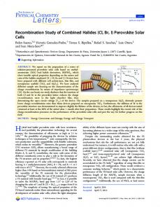
Results and Discussion A diagram and photos of the encapsulated cell are shown in Figure 1. It should be noted that the top metal contacts are completely covered in the encapsulated devices, and the contact to the device for both top and bottom electrodes are made using the etched contact pad pattern on the FTO substrate. Furthermore, contact probes instead of crocodile clips are used to connect the cells to avoid contact damage. In our previous encapsulation designs,[30] we have used silver or carbon paint at the contacts. Silver paint resulted in better initial cell performance compared to carbon paint owing to its higher conductivity, but the contacts to the cells degraded over time of testing. No significant contact degradation is observed in the present packaging design. Furthermore, unlike the previous report,[28] we have not observed a drop in the efficiency for encapsulated cells owing to the fact that cells mea-
Figure 1. a) Diagram of the encapsulated cell. b) Photos of the encapsulated cell, front (left) and back (right). c) Outdoor testing setup.
ChemSusChem 2016, 9, 2597 – 2603
www.chemsuschem.org
2598
T 2016 Wiley-VCH Verlag GmbH & Co. KGaA, Weinheim
Full Papers sured without encapsulation typically yielded somewhat lower efficiencies in a high ambient humidity environment and exhibit damaged electrodes after measurement (see the Supporting Information, Figures S1 and S2). Other possible reasons for the differences in the performance compared to previous report[28] include different epoxy used, differences in making the contact to the cells, and the fact that metal electrode is fully covered in our encapsulation. However, we observed a significant drop in the initial efficiency for the thermally curable epoxy. Representative current voltage (I–V) curves for cells encapsulated by different epoxies are shown in Figure 2. Cells sealed with a thermally curable epoxy exhibited significantly lower short-circuit current density (JSC) and fill factor (FF), as well as more pronounced hysteresis. The cells encapsulated with a UV-curable epoxy exhibit a JSC of 21.6 mA cm@2, open circuit voltage (VOC) of 1.04 V, and FF of 0.66, resulting in a PCE of 14.8 % (reverse scan). There is some hysteresis, as is common for planar devices, so that the efficiency under forward scan is 9.9 %, mainly owing to a drop in
Figure 2. I–V curves of TiO2-based PSCs encapsulated with different sealant materials: a) UV-curable epoxy, b) AB epoxy glue, and c) thermally curable epoxy.
ChemSusChem 2016, 9, 2597 – 2603
www.chemsuschem.org
VOC (0.93 V) and FF (0.51). The cell encapsulated with AB glue (see Experimental Section for details) exhibits similar performance, with JSC = 22.0 mA cm@2, VOC = 0.98 V, FF = 0.65, and PCE = 14.0 % (9.0 % under forward scan). On the other hand, the efficiency of cells sealed with a thermally cured epoxy is only 8.9 % (4.2 % under forward scan). This is mainly owing to the lower JSC (17.8 mA cm@2) and FF (0.51 for reverse scan, and only 0.28 for forward scan). Inferior performance of cells sealed with a thermally curable epoxy could occur owing to thermal instability of the perovskite[31] or the damage of the perovskite layer resulting from outgassing from the epoxy during thermal curing. As the devices sealed by the other two epoxies were subjected to stability testing at 85 8C and exhibited stable performance for some encapsulation methods, thermal instability of the perovskite was likely not the cause of observed inferior performance, especially because the epoxy was cured at a lower temperature of 80 8C. Thus, it is likely that the outgassing of the epoxy during thermal curing has detrimental effects on the PSC performance. It has been previously shown that the outgassing of the epoxy affects the performance of organic solar cells.[42] Consequently, UV-curable epoxies are likely to yield better performance for encapsulating PSCs compared to thermally curable epoxies. Owing to the inferior performance of the cells encapsulated using thermally curable epoxy, the stability of these devices was not tested further. We have compared the stability of the devices encapsulated using the other two epoxies and the obtained results (PCE of representative devices) are shown in Figure 3. It can be observed that the performance of devices encapsulated with a UV-curable epoxy is significantly better compared to AB epoxy. The devices encapsulated with an AB glue exhibit more rapid drop of the efficiency in the first few hours of stability testing and then they stabilize, but at a significantly lower efficiency compared to those encapsulated with a UV-curable epoxy. In the latter case, cells able to maintain ~ 90 % of their initial efficiency after 48 h of light soaking at 85 8C and 65 % relative humidity (RH) could be obtained. After identifying the most suitable epoxy, we further tested different possible enhancement strategies, such as the effect of desiccant, and two protective layers [graphene oxide (GO)
Figure 3. PCE of TiO2-based devices with different encapsulation epoxy under continuous illumination at 85 8C and 65 % RH as a function of time. The encapsulation included the deposition of a SiO2 film and the use of a desiccant.
2599
T 2016 Wiley-VCH Verlag GmbH & Co. KGaA, Weinheim
Full Papers
Figure 4. PCE of TiO2-based devices with different encapsulation strategies (using UV-curable epoxy) under continuous illumination at 85 8C and 65 % RH as a function of time.
Figure 5. PCE of TiO2- and ZnO-based devices with the best encapsulation condition under continuous illumination at 85 8C and 65 % RH as a function of time.
and SiO2]. Obtained average PCE values (for 3–6 devices) are shown in Figure 4, with the standard deviation indicated by error bars. It can be observed that the best performance is obtained for the devices protected with a SiO2 film and encapsulated with desiccant. Similar to previous work,[28] the inclusion of the desiccant improved the stability of the devices. However, the GO layer did not improve the stability of the devices. It was previously reported that the use of GO in the hole-transport layer resulted in a slower degradation of the perovskite film when exposed to ambient atmosphere.[17] However, in this case the GO-containing hole-transport layer was located below the perovskite layer.[17] We have spin-coated the GO layer on top of the finished device, which could contribute to the observed differences. Owing to the possibility of incomplete coverage of GO, and the fact that the layer is solution processed, which can lead to some outgassing during the initial stages of testing, vapor phase deposited films would be preferred for additional protection. The deposited SiO2 layer can serve to protect the electrode during the measurement in the ambient, as the electrode of unencapsulated cells rapidly degrades in a humid environment (see the Supporting Information, Figure S1). Once a suitable encapsulation method was established, we prepared cells based on ZnO and TiO2 and compared their stability. It was previously reported that ZnO-based PSCs exhibited inferior stability compared to TiO2-based PSCs.[33] Perovskite films also exhibited lower thermal stability on ZnO compared to TiO2.[33] The inferior stability of perovskite film on ZnO was attributed to the presence of surface hydroxyl groups and/or acetate ligands, as well as higher basicity of ZnO, which could result in deprotonation of the methylammonium cation and hence perovskite degradation.[33, 37] We have also found that the perovskite films on ZnO were less thermally stable, and thus the annealing of the perovskite film was performed at a lower temperature. The obtained films exhibited smaller grain size compared to perovskite films on TiO2 (see the Supporting Information, Figure S3), and a lower initial efficiency was obtained. However, the biggest drawback of ZnO-based cells was their significantly lower stability under accelerated aging compared to TiO2-based cells, as shown in Figure 5. This is likely at least partly a result of the thermal instability of the
perovskite film on ZnO.[33, 37] Thus, stability comparisons could be performed at 65 8C for accelerated testing or at ambient temperature over a longer period of time in the future to establish whether the poor stability is mainly a result of the thermal instability of perovskite on ZnO, or other contributing factors. Nevertheless, it is obvious that ZnO-based cells exhibit significantly lower stability compared to TiO2-based cells. Possible improvement strategies may include deposition of interfacial layers between the ZnO and perovskite layers. For example, it has been shown that the performance of ZnO-based PSCs improves both in terms of efficiency and stability if a thin Al2O3 layer is inserted between ZnO and the mesoporous TiO2 layer.[32] However, this requires further study. As the TiO2 based cells encapsulated with an optimal encapsulation process exhibited good stability in the initial testing,
ChemSusChem 2016, 9, 2597 – 2603
www.chemsuschem.org
Figure 6. PCE of TiO2-based devices with the best encapsulation condition a) under continuous illumination at 85 8C and 65 % RH as a function of time (best device) and b) for outdoor testing (average of three devices).
2600
T 2016 Wiley-VCH Verlag GmbH & Co. KGaA, Weinheim
Full Papers longer stability testing was performed under accelerated aging, as well as in the outdoor environment. Figure 6 shows the PCE as a function of time for the best performing device (for the corresponding curves for all devices and for the change of individual performance parameters with time, see the Supporting information, Figures S4 and S5). Similar to our previous work, the devices show faster degradation in the first 6–10 h, and then significantly slower degradation can be observed.[30] Faster initial degradation followed by stable performance has been previously observed in PSCs.[13, 38, 39] Initial degradation was attributed to different possible factors, such as partial de-doping of spiro-OMeTAD, oxygen desorption from TiO2, changes at the contact, or changes in the perovskite absorber.[38] Similar behavior (fast initial degradation followed by stable performance) was also observed in organic solar cells.[42–45] Degradation processes in organic photovoltaics have been more comprehensively studied, including the processes responsible for the initial degradation, or the so-called burn-in loss. The burn-in loss was attributed to the formation of subbandgap states in the active layer owing to photo-induced reactions.[44, 45] However, it was also proposed that multiple concurrent processes are responsible for the burn-in loss, and that the origins of the burn-in loss are material dependent.[43] Furthermore, possible contribution of the outgassing of moisture from the encapsulant materials to the burn-in loss cannot be excluded.[42] While the origin of the burn-in losses in perovskite devices requires further study and could likely be reduced by device architecture optimization, it is important to note that, after the initial degradation, the performance stabilizes, or even improves over time, depending on testing conditions. Despite longer testing time compared to previous work,[28] the device performance remains relatively stable after the initial degradation, and in some devices a recovery of the efficiency is observed. The VOC exhibits small changes during the degradation, while the major drop in the efficiency occurs owing to the reduced FF and reduced JSC. The reasons for the unexpected efficiency recovery are not fully clear, but they may be related to prolonged operation at elevated temperature, as no such efficiency recovery occurs for cells tested according to ISOS-O-1 protocol in our work. Previously, a PCE increase was reported after 5 days of outdoor testing in Jeddah, Saudi Arabia, whereas no such increase was observed for testing at 80–85 8C in ambient air (ISOS-D-2 testing protocol).[29, 39] In our work, the cells subjected to outdoor testing also exhibited fast decay in the first 6 h, and then significantly slower decay. The average PCE decreased from 15.3 to 12.2 % in the first 6 h, and then the performance stabilized at ~ 11 % from 30 to 432 h. Similar to accelerated aging, the main decrease in the PCE over time is a result of a decrease in FF and, to a smaller extent, a decrease in JSC. In fact, the PCE time dependence follows the FF time dependence. The FF exhibits a fast decrease in the first 6 h and then stabilizes, while JSC exhibits a slow decrease over time and then stabilizes. The differences between our work and a previous report on outdoor testing[29, 39] are likely because of a difference in the device structure as well as a significant difference in humidity. RH in Jeddah in September, when the testing was done in a previous ChemSusChem 2016, 9, 2597 – 2603
www.chemsuschem.org
report,[39] is in the range 60–70 % (comparable to our indoor testing condition at 65 %) and there is typically no rain in September. On the other hand, humidity in June in Hong Kong is very high (mean value of ~ 80 %) and it frequently rains. During our tests, the humidity variations in the range 30–90 % were observed during the day, and it was raining on several occasions. For temperature and humidity variations during outdoor testing, see the Supporting Information (Figure S7). The fact that the cell performance after the initial burn-in stabilized at a respectable efficiency of ~ 11 %, and remained stable from approximately 30 to 432 h, indicates that despite the sensitivity of perovskite materials to humidity, the PSCs can exhibit stable performance in a high humidity environment with proper encapsulation. It should be noted that further improvements in the stability are possible by implementing various strategies for device stability improvement (e.g., modifications of the perovskite composition, change of the charge-transport layers, insertion of interfacial and/or barrier layers, and/or use of high work function chemically inert electrodes). In terms of further improvements in the encapsulation, it is likely that state-ofthe-art methods from organic LED encapsulation would yield good performance. This typically requires the use of desiccant in addition to a low moisture permeability encapsulation material. Elimination of the desiccant may be possible by elimination of various contributors to moisture and/or oxygen outgassing during device operation, further lowering of the water vapor transmission rate of the epoxy, and elimination of the moisture outgassing from the epoxy, as well as improved edge sealing or deposition of multilayer protective coating instead of a simple SiO2 film.
Conclusions We have examined the effect of encapsulation on the stability of perovskite solar cells (PSCs). We found that the UV-curable epoxy results in better performance compared to thermally curable epoxy. With an appropriate epoxy selection, the use of desiccant and the deposition of protective SiO2 films, stable performance of TiO2-based planar PSCs can be obtained under constant light soaking at 65 % relative humidity (RH) and 85 8C. However, optimized encapsulation that was sufficient for TiO2based devices failed to protect ZnO-based devices from rapid performance degradation. In addition to laboratory weathering, outdoor testing was also performed. After initial performance decay (within the first 6 h), the cells exhibited stable performance despite the fact that the RH exceeded 80 % and occasional rain occurred during the testing period. This indicates that with adequate encapsulation, PSCs are promising for practical application despite the sensitivity of the perovskite material to ambient humidity (in particular under illumination).
Experimental Section Materials: Titanium (IV) isopropoxide (TTIP, 97 %), zinc acetate (99.99 %), 2-methoxyethanol (+ 99.3 %), ethanolamine (+ 99.0 %), lead iodide (PbI2, 99 %), bis (trifluoromethane) sulfonamide lithium
2601
T 2016 Wiley-VCH Verlag GmbH & Co. KGaA, Weinheim
Full Papers salt (Li-TFSI, 99.95 %), 4-tert butylpyridine (96 %), chlorobenzene (+ 99.5 %), and acetonitrile (anhydrous, 99.8 %) were purchased from Sigma–Aldrich. Methylammonium iodide (MAI) was purchased from Dyesol. Acetic acid (GR grade) was purchased from Duksan Pure Chemical. N,N-Dimethylformamide (DMF, anhydrous, 99.9 + %) and 2-propanol (anhydrous, 99.5 + %) were obtained from Alfa Aesar. Spiro-OMeTAD was purchased from Shenzhen Feiming Co., Ltd. Solar cell preparation: Patterned FTO/glass substrates were sequentially cleaned by sonication in toluene, acetone, ethanol, and deionized water. PbI2 was dissolved in anhydrous DMF at 1 m and stirred at 70 8C, while MAI was dissolved in anhydrous 2-propanol at 30 mg mL@1 and stirred at room temperature. For TiO2-based devices, the TiO2 compact layer was prepared by spin coating of an acidic TTIP precursor solution (50 mL of TTIP and 50 mL of acetic acid dissolved in 2 mL of ethanol), followed by sintering at 450 8C for 3 h. The perovskite film on the TiO2 compact layer was synthesized following a conventional two-step procedure.[30] Briefly, a PbI2 layer was first spin-coated onto the substrate at 2500 rpm for 30 s and subsequently annealed at 70 8C for 30 min. A MAI solution was then placed onto the PbI2 layer for 1 min, followed by spin-coating at 2500 rpm for 30 s. The obtained films were annealed at 100 8C overnight. For ZnO-based devices, a sol-gel precursor solution was prepared by dissolving zinc acetate in 2-methoxyethanol at 40 mg mL@1 with 3 % ethanolamine added. The precursor solution was stirred at 80 8C for 3 h, and spin-coated onto the FTO/glass substrates at 4000 rpm for 30 s. The obtained film was sintered at 350 8C for 1 h to obtain a ZnO compact layer. For the synthesis of perovskite films, a PbI2 solution was spin-coated on ZnO compact layer at 3000 rpm for 30 s, followed by annealing at 60 8C for 30 min. A MAI solution was placed onto the as-prepared PbI2 layer for 1 min and spun at 2500 rpm for 30 s. The film was annealed at 70 8C for 1 h to achieve complete crystallization of perovskites. The morphology of the as synthesized perovskite films on different compact layers were characterized with a JEOL JMS-7001F scanning electron microscope. After preparation of the perovskite layer, the hole-transporting layer was deposited onto the perovskite film by spin coating a precursor solution [72.3 mg of spiro-OMeTAD dissolved in 1 mL of chlorobenzene, added with 28.8 mL of 4-tert-butylpyridine and 17.5 mL of Li-TFSI solution (520 mg dissolved in 1 mL of acetonitrile)] at 4000 rpm for 30 s and annealed at 40 8C in oxygen for 1 h. Oxygen annealing of spiro-OMeTAD was found to improve the device performance.[46] To minimize exposure to ambient humidity during the oxygen annealing, devices were transferred to a vacuum oven, the oven was pumped to vacuum and flushed with nitrogen twice before pumping down and filling up with oxygen to atmospheric pressure. After the annealing, a bilayer electrode (15 nm of MoO3 and 100 nm of Al) was deposited via thermal evaporation. Encapsulation: Different encapsulation strategies were investigated. The devices were encapsulated in different conditions: (1) the active area of the device covered with a 1 mm glass only; (2) the active area of the device covered with a 1 mm glass and a piece of desiccant (180 mm thickness, Dynic Corporation); (3) the active area of the device was covered with a 50 nm of SiO2 layer deposited using electron beam deposition, and then protected by a cover glass with a piece of desiccant; (4) the active area of the device covered with a thin layer of graphene oxide and a cover glass with a piece of desiccant. In addition, three distinct types of epoxies were tested as the sealant materials, including a UV-curable epoxy (ThreeBond), an AB epoxy glue (Super Glue Corp.), as well as a thermally curable epoxy (Kyoritsu Chemical). When using UV or ther-
ChemSusChem 2016, 9, 2597 – 2603
www.chemsuschem.org
mally curable epoxy as the sealant material, the minimally required amount of epoxy was carefully applied along the edges of the cover glass, cured under appropriate conditions (1 min of UV illumination for UV-curable epoxy, and annealed at 80 8C for 10 min under UV illumination for thermally curable epoxy). When using AB epoxy glue as the sealant material, the appropriate amount of epoxy was placed onto the device so that the whole active area was completely covered. The device was further dried for 10 min to allow complete solidification of the AB glue. All the devices were encapsulated inside a glove box. Solar cell characterization: Stability testing of the encapsulated device was conducted in both laboratory and outdoor environment, following the procedures described in testing protocols ISOS-L-2 and ISOS-O-1. For laboratory weathering testing, devices were placed on a hot plate at 85 8C under a constant AM 1.5 G illumination from an ABET Sun 2000 solar simulator at an intensity of 100 mW cm@2. For outdoor testing, devices were mounted at 228 with the front side oriented towards the equator. The RH of the ambient environment was monitored for both testing conditions. The RH in the laboratory environment was 65 %, whereas the RH for outdoor testing ranged from 30 to 90 % RH, depending on the weather and the time of a day (low humidity around noon on sunny days, high humidity in the evenings; rain also occurred during the testing period). I–V characterization of each device was performed at specified intervals under simulated AM 1.5 G illumination at 100 mW cm@2. The J–V curves were scanned from 1.2 to @0.2 V at a step of 0.01 V with a delay time of 0.01 s.
Acknowledgements Financial support from the ECF project 35/2015, as well as Strategic Research Theme, University Development Fund, and Seed Funding for Basic Research of the University of Hong Kong is acknowledged. The authors would like to thank Mr. W. C. Liu from Dept. of Physics, University of Hong Kong for designing the outdoor mount for solar cell stability testing. Keywords: degradation · encapsulation · organometallic halide perovskite · solar cells · stability [1] H.-S. Kim, C.-R. Lee, J.-H. Im, K.-B. Lee, T. Moehl, A. Marchioro, S.-J. Moon, R. Humphry-Baker, J.-H. Yum, J. E. Moser, M. Gr-tzel, N.-G. Park, Sci. Rep. 2012, 2, 591. [2] M. M. Lee, J. Teuscher, T. Miyasaka, T. N. Murakami, H. J. Snaith, Science 2012, 338, 643 – 647. [3] W. S. Yang, J. H. Noh, N. J. Jeon, Y. C. Kim, S. Ryu, J. Seo, S. I. Seok, Science 2015, 348, 1234 – 1237. [4] N. H. Tiep, Z. Ku, H. J. Fan, Adv. Energy Mater. 2016, 6, 1501420. [5] M. Ye, X. Hong, F. Zhang, X. Liu, J. Mater. Chem. A 2016, 4, 6755 – 6771. [6] D. Bi, P. Gao, R. Scopelliti, E. Oveisi, J. Luo, M. Gr-tzel, A. Hagfeldt, M. K. Nazeeruddin, Adv. Mater. 2016, 28, 2910 – 2915. [7] C. Chen, M. Cheng, P. Liu, J. Gao, L. Kloo, L. Sun, Nano Energy 2016, 23, 40 – 49. [8] D. Bi, B. Xu, P. Gao, L. Sun, M. Gr-tzel, A. Hagfeldt, Nano Energy 2016, 23, 138 – 144. [9] D. Bi, W. Tress, M. I. Dar, P. Gao, J. Luo, C. Renevier, K. Schenk, A. Abate, F. Giordano, J.-P. C. Baena, J.-D. Decoppet, S. M. Zakeeruddin, M. K. Nazeeruddin, M. Gr-tzel, A. Hagfeldt, Sci. Adv. 2016, 2, e1501170. [10] J. A. Christians, P. A. M. Herrera, P. V. Kamat, J. Am. Chem. Soc. 2015, 137, 1530 – 1538. [11] D. Song, D. Wei, P. Cui, M. Li, Z. Duan, T. Wang, J. Ji, Y. Li, J. M. Mbengue, Y. Li, Y. He, M. Trevor, N.-G. Park, J. Mater. Chem. A 2016, 4, 6091 – 6097.
2602
T 2016 Wiley-VCH Verlag GmbH & Co. KGaA, Weinheim
Full Papers [12] Y.-K. Wang, Z.-C. Yuan, G.-Z. Shi, Y.-X. Li, Q. Li, F. Hui, B.-Q. Sun, Z.-Q. Jiang, L.-S. Liao, Adv. Funct. Mater. 2016, 26, 1375 – 1381. [13] X. Xia, W. Wu, H. Li, B. Zheng, Y. Xue, J. Xu, D. Zhang, C. Gao, X. Liu, RSC Adv. 2016, 6, 14792 – 14798. [14] W. Zhu, C. Bao, F. Li, T. Yu, H. Gao, Y. Yi, J. Yang, G. Fu, X. Zhou, Z. Zou, Nano Energy 2016, 19, 17 – 26. [15] F. Igbari, M. Li, Y. Hu, Z.-K. Wang, L.-S. Liao, J. Mater. Chem. A 2016, 4, 1326 – 1335. [16] J. You, L. Meng, T.-B. Song, T.-F. Guo, Y. Yang, W.-H. Chang, Z. Hong, H. Chen, H. Zhou, Q. Chen, Y. Liu, N. De Marco, Y. Yang, Nat. Nanotechnol. 2016, 11, 75 – 82. [17] D.-Y. Lee, S.-I. Na, S.-S. Kim, Nanoscale 2016, 8, 1513 – 1522. [18] J. Xu, O. Voznyy, R. Comin, X. Gong, G. Walters, M. Liu, P. Kanjanaboos, X. Lan, E. H. Sargent, Adv. Mater. 2016, 28, 2807 – 2815. [19] Z. L. Zhu, Y. Bai, X. Liu, C.-C. Chueh, S. H. Yang, A. K.-Y. Jen, Adv. Mater. 2016, DOI: 10.1002/adma.201600619. [20] Y. Dkhissi, H. Weerasinghe, S. Meyer, I. Benesperi, U. Bach, L. Spiccia, R. A. Caruso, Y.-B. Cheng, Nano Energy 2016, 22, 211 – 222. [21] A. Agresti, S. Pescetelli, L. Cin/, D. Konios, G. Kakavelakis, E. Kymakis, A. Di Carlo, Adv. Funct. Mater. 2016, 26, 2686 – 2694. [22] F. X. Xie, D. Zhang, H. Su, X. Ren, K. S. Wong, M. Gr-tzel, W. C. H. Choy, ACS Nano 2015, 9, 639 – 646. [23] S. Guarnera, A. Abate, W. Zhang, J. M. Foster, G. Richardson, A. Petrozza, H. J. Snaith, J. Phys. Chem. Lett. 2015, 6, 432 – 437. [24] F. T. F. O’Mahony, Y. H. Lee, C. Jellett, S. Dmitrov, D. T. J. Bryant, J. R. Durrant, B. C. O’Regan, M. Graetzel, M. K. Nazeeruddin, S. A. Haque, J. Mater. Chem. A 2015, 3, 7219 – 7223. [25] C. Law, L. Miseikis, S. Dimitrov, P. Shakya-Tuladhar, X. Li, P. R. F. Barnes, J. Durrant, B. C. O’Regan, Adv. Mater. 2014, 26, 6268 – 6273. [26] F. K. Aldibaja, L. Badia, E. Mas-Marz#, R. S. S#nchez, E. M. Barea, I. MoraSero, J. Mater. Chem. A 2015, 3, 9194 – 9200. [27] C.-Y. Chang, Y.-C. Chang, W.-K. Huang, W.-C. Liao, H. Wang, C. Yeh, B.-C. Tsai, Y.-C. Huang, C.-S. Tsao, J. Mater. Chem. A 2016, 4, 7903 – 7913. [28] Y. Han, S. Meyer, Y. Dkhissi, K. Weber, J. M. Pringle, U. Bach, L. Spiccia, Y.B. Cheng, J. Mater. Chem. A 2015, 3, 8139 – 8147. [29] B. Li, Y. Li, C. Zheng, D. Gao, W. Huang, RSC Adv. 2016, 6, 38079 – 38091. [30] F. Liu, Q. Dong, M. K. Wong, A. B. Djurisˇic´, A. Ng, Z. Ren, Q. Shen, C. Surya, W. K. Chan, J. Wang, A. M. C. Ng, C. Lia, H. Li, K. Shih, C. Wei, H. Su, J. Dai, Adv. Energy Mater. 2016, 6, 1502206. [31] B. Conings, J. Drijkoningen, N. Gauquelin, A. Babayigit, J. D’Haen, L. D’Olieslaeger, A. Ethirajan, J. Verbeeck, J. Manca, E. Mosconi, F. De Angelis, H.-G. Boyen, Adv. Energy Mater. 2015, 5, 1500477. [32] H. Si, Q. Liao, Z. Zhang, Y. Li, X. Yang, G. Zhang, Z. Kang, Y. Zhang, Nano Energy 2016, 22, 223 – 231.
ChemSusChem 2016, 9, 2597 – 2603
www.chemsuschem.org
[33] Y. Dkhissi, S. Meyer, D. H. Chen, H. C. Weerasinghe, L. Spiccia, Y.-B. Cheng, R. A. Caruso, ChemSusChem 2016, 9, 687 – 695. [34] G. Niu, W. Li, F. Meng, L. Wang, H. Dong, Y, Qiu, J. Mater. Chem. A 2014, 2, 705 – 710. [35] Y. Li, X. Xu, C. Wang, C. Wang, F, Xie, J. Yang, Y. Gao, J. Mater. Chem. C 2015, 3, 23996 – 24002. [36] I. Deretzis, A. Alberti, G. Pellegrino, E. Smecca, F. Giannazzo, N. Sakai, T. Miyasaka, A. La Magna, Appl. Phys. Lett. 2015, 106, 131904. [37] J. Yang, B. D. Siempelkamp, D. Liu, T. L. Kelly, ACS Nano 2015, 9, 1955 – 1963. [38] T. Leijtens, G. E. Eperon, S. Pathak, A. Abate, M. M. Lee, H. J. Snaith, Nat. Commun. 2013, 4, 2885. [39] X. Li, M. Tschumi, H. W. Han, S. S. Babkair, R. A. Alzubaydi, A. A. Ansari, S. S. Habib, M. K. Nazeeruddin, S. M. Zakeeruddin, M. Gr-tzel, Energy Technol. 2015, 3, 551 – 555. [40] F. Zhang, C. Y. Yi, P. Wei, X. D. Bi, J. S. Luo, G. Jacopin, S. R. Wang, X. G. Li, Y. Xiao, S. M. Zakeeruddin, M. Gr-tzel, Adv. Energy Mater. 2016, 6, 1600401. [41] M. O. Reese, S. A. Gevorgyan, M. Jørgensen, E. Bundgaard, S. R. Kurtz, D. S. Ginley, D. C. Olson, M. T. Lloyd, P. Morvillo, E. A. Katz, A. Elschner, O. Haillant, T. R. Currier, V. Shrotriya, M. Hermenau, M. Riede, K. R. Kirov, G. Trimmel, T. Rath, O. Ingan-s, F. L. Zhang, M. Andersson, K. Tvingstedt, M. Lira-Cantu, D. Laird, C. McGuiness, S. Gowrisanker, M. Pannone, M. Xiao, J. Hauch, R. Steim, D. M. DeLongchamp, R. Rçsch, H. Hoppe, N. Espinosa, A. Urbina, G. Yaman-Uzunoglu, J. B. Bonekamp, A. J. J. M. van Breemen, C. Girotto, E. Voroshazi, F. C. Krebs, Sol. Energy Mater. Sol. Cells 2011, 95, 1253 – 1267. [42] H. C. Weerasinghe, S. E. Watkins, N. Duffy, D. J. Jones, A. D. Scully, Sol. Energy Mater. Sol. Cells 2015, 132, 485 – 491. [43] E. Voroshazi, I. Cardinaletti, T. Conard, B. P. Rand, Adv. Energy Mater. 2014, 4, 1400848. [44] C. H. Peters, I. T. Sachs-Quintana, W. R. Mateker, T. Heumueller, J. Rivnay, R. Noriega, Z. M. Beiley, E. T. Hoke, A. Salleo, M. D. McGehee, Adv. Mater. 2012, 24, 663 – 668. [45] Y. W. Zhang, E. Bovill, J. Kingsley, A. R. Buckley, H. N. Yi, A. Iraqi, T. Wang, D. G. Lidzey, Sci. Rep. 2016, 6, 21632. [46] Z.-W. Ren, A. Ng, Q. Shen, H. C. Gokkaya, J. C. Wang, L. J. Yang, W. K. Yiu, G. X. Bai, A. B. Djurisˇic´, W. K. Chan, W. W. F. Leung, J. H. Hao, W. K. Chan, C. Surya, Sci. Rep. 2014, 4, 6752.
Received: June 30, 2016 Published online on August 9, 2016
2603
T 2016 Wiley-VCH Verlag GmbH & Co. KGaA, Weinheim