demonstrated, for the domain of engineering systems modelling, simulation and design. ... intelligent support for physical systems engineering. Take as a simple ...
Int. J. Human – Computer Studies (1997) 46 , 365 – 406
Engineering ontologies PIM BORST† AND HANS AKKERMANS‡ Uniy ersity of Twente , Information Systems Department INF / IS , P .O. Box 217 , NL-7500 AE Enschede , The Netherlands. email: borst / akkermanêcs.utwente.nl JAN TOP Agro-Technological Research Organization ATO-DLO , P .O. Box 17 , NL-6700 AA Wageningen , The Netherlands . email: j.l.topêato.dlo .nl We analyse the construction as well as the role of ontologies in knowledge sharing and reuse for complex industrial applications. In this article, the practical use of ontologies in large-scale applications not restricted to knowledge-based systems is demonstrated, for the domain of engineering systems modelling, simulation and design. A general and formal ontology, called PHYSSYS, for dynamic physical systems is presented and its structuring principles are discussed. We show how the PHYSSYS ontology provides the foundation for the conceptual database schema of a library of reusable engineering model components, covering a variety of disciplines such as mechatronics and thermodynamics, and we describe a full-scale numerical simulation experiment on this basis pertaining to an existing large hospital heating installation. From the application scenario, several general guidelines and experiences emerge. It is possible to identify various y iewpoints that are seen as natural within a large domain: broad and stable conceptual distinctions that give rise to a categorization of concepts and properties. This provides a first mechanism to break up ontologies into smaller pieces with strong internal coherence but relatively loose coupling, thus reducing ontological commitments. Secondly, we show how general and abstract ontological super theories , for example mereology, topology, graph theory and systems theory, can be used and reused as generic building blocks in ontology construction. We believe that this is an important element in knowledge sharing across domains. Thirdly, we introduce ontology projections as a flexible means to connect different base ontologies. Ontology projections can occur in simple forms such as include-and-extent and include-and-specialize, but are in their richest form very knowledge-intensive, being in fact themselves full-blown ontological theories. ÷1997 Academic Press Limited
1. Introduction Ontologies have been proposed as a specification mechanism to enhance knowledge sharing and reuse across different applications (Neches et al. , 1991). To do so, they must capture the intended meaning of concepts and statements in a domain. Sharing and reuse imply two additional requirements: (i) ontologies must aim at a maximum level of genericity and thus bring out the commonalities within extensive bodies of detailed and specialized knowledge, and (ii) they must be able to explicate tacit and meta-level knowledge, as significant parts of domain expertise are highly implicit and have a background nature. † Corresponding author. ‡ Also at: Netherlands Energy Research Foundation ECN, P.O. Box 1, NL-1755 TG Petten (NH), The Netherlands. email: akkermansêecn.nl. 365 1071-5819 / 97 / 2130365 1 00$25.00 / 0 / hc960096
÷ 1997 Academic Press Limited
366
P. BORST ET AL.
These aspects are all clearly present in the area we consider in this article: intelligent support for physical systems engineering. Take as a simple example the expression F 5 ma. Many people will immediately associate this with Newton’s law stating that force is the product of mass and acceleration. But this is a highly nontrivial association, because it can only be made by invoking a lot of background knowledge. First, we have to know that we are dealing here with a mathematical expression, and we have to understand the related concepts of equations, parameters and variables. However, this is far from enough: the intended meaning of F 5 ma may now still be that electrical voltage is the product of resistance and current (which, instead, many people would call Ohm’s law and typically write as V 5 IR ). To distinguish between such possible interpretations we need more knowledge about, for example, the concept of physical dimensions of variables. To capture the intended meaning of F 5 ma in the context of its use in problem soly ing , we have to additionally invoke a significant body of expert knowledge. For example, we have to understand that in this context of problem-solving use, physical objects are abstracted to and parameterized in terms of a concept called ‘‘mass’’, that this mass acts as a kind of storage place for movement, that this movement does not change when the mass is undisturbed, and that it does change under certain external influences and circumstances which are abstracted to and parameterized in terms of concept called ‘‘force’’, and so on. That is, in specifying intended meaning we unavoidably have jumped into a background body of specialist knowledge known as classical mechanics. If ontologies are to enhance knowledge sharing and reuse by capturing intended meaning, the above-mentioned issues have to be confronted. Current information systems supporting complex tasks and domains typically do not possess the body of knowledge necessary for generating adequate interpretations, but instead rely on the fact that the user does. So, they place most of the burden on the user. Intelligent support implies that this burden must be shifted back as much as possible towards the information system. Ontologies are a promising candidate to help achieve this, but to realize this potential we need a better understanding both of their role in complex problem solving and of their construction. The present work investigates this subject, illustrated by various aspects of physical systems engineering. The paper contains two main lines. Section 2 gives an overview of a general collection of ontologies for physical systems, whereby we attempt to clarify throughout how we can achieve genericity in ontological specifications, what general decomposition and structuring principles play a role, and how we can reuse existing other ontologies. Sections 3 and 4 are more domainspecific and demonstrate the practical relevance and use of ontologies for demanding industrial engineering domains and tasks. Thus, we follow the complete route from formal ontology construction (PHYSSYS, Section 2), via the ontology-based design specs of an implemented library of reusable models (OLMECO, Section 3), to the daily task execution by domain experts (numerical system simulation, Section 4). We believe that many of our experiences and results are independent of the considered domain, and have a general relevance for the engineering of ontologies. In Sections 5 and 6 we resume the general discussion and discuss the conclusions emerging from the present work in more detail, and compare them with related ongoing work.
ENGINEERING ONTOLOGIES
367
2. The PHYSSYS ontology PHYSSYS is a formal ontology based upon system dynamics theory as practiced in engineering modelling, simulation and design. It forms the basis for the OLMECO library, a model component library for physical systems like heating systems, automotive systems and machine tools. The ontology expresses different conceptual viewpoints on a physical system. To demonstrate what these viewpoints are, we carry out the small exercise of determining the knowledge that is required to understand the formula F 5 ma. Anybody who paid attention during physics class at High School knows that this formula is Newton’s law that describes the acceleration of an object under the influence of a force. Unfortunately, for a computer this is not obvious at all. When a user types in the formula on the console, it is just a string of characters. Assuming the computer knows about mathematics, this string will be parsed and identified as a mathematical formula, a relation between variables. The mathematical knowledge must include the facts that variable stands for a certain value that may or may not change in time (or another free variable) and that possibly has a certain dimension. Knowing this, F 5 ma just means that the value of one variable is equal to the product of the value of two other variables, at any time. The system still knows nothing about its meaning in terms of physics. In order to make the computer understand the physical implication of the formula it must know about physical processes, energy and physical domains. It must know that a formula can be a mathematical description of a physical process like the inertial effect of a mass. At this point it also becomes clear that a mathematical variable represents a certain physical quantity. In the F 5 ma example, F is a force quantity, m stands for a mass and a for an acceleration. Without this knowledge F 5 ma could also have meant that the voltage F is equal to a resistance m multiplied by the electrical current a. With this interpretation, the equation would have been another famous physical law called Ohm’s law (usually written down as V 5 IR ) that describes the process of electrical resistance. The final step is to introduce the relation between the physical processes and the real world physical system. For this, knowledge of how people look upon physical systems is required. In engineering it is customary to think of the system as a configuration of components which on their turn can be decomposed into smaller components. Connections between components are the means for interaction. In these terms, the mass could be a heavy object hoisted by a crane. The load and cable would be two components connected to each other by a mechanical connection. Each component is the carrier of physical processes. The load component is the carrier of the inertial effect and its interaction with the cable component implies an energy flow between the physical processes modelling the two components. Accordingly, it is clear that three conceptual viewpoints on physical systems can be distinguished: (i) system layout, (ii) physical processes underlying behaviour and (iii) descriptive mathematical relations. The PHYSSYS ontology consists of three engineering ontologies formalizing these viewpoints. The interdependencies between these ontologies are formalized as ontology projections. Furthermore, the viewpoints themselves are constructed from smaller abstract ontologies. The whole set
368
P. BORST ET AL.
Mereology Extend Topology Extend Systems theory Specialize Component View of
Specialize Process View of
EngMath View of
PhysSys
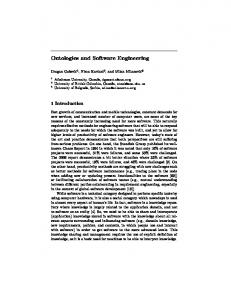
FIGURE 1. Inclusion lattice of the PHYSSYS ontology.
of ontologies used contains ontologies of varying genericity and abstractness. Identifying these separate ontologies not only makes it easier to understand the domain because classes and ontological commitments are added incrementally, it also increases the ability to share and reuse parts of PHYSSYS. Figure 1 gives an overview of the structure of the PHYSSYS ontology (Borst, Pos, Top & Akkermans 1994; Borst, Akkermans, Pos & Top, 1995). Boxes represent separate ontologies whereas labelled arrows indicate ontology inclusion. The labels next to the arrows show the kind of inclusion. As can be seen in the figure, the PHYSSYS ontology consists of three primary ontologies which are formalizations of the three views on the physical domain. In the next sections these ontologies will be explained as well as the meteorological, topological and system theory ontologies that are used in both the component and process ontologies. Special attention will be given to the ontology projections , which are the formalizations of the interdependencies between included ontologies.
2.1. COMPONENT ONTOLOGY
One particular viewpoint on a physical system is that it is a system in the sense of general systems theory. That is, it constitutes an entity that (i) can be seen as separate from the rest of the world—so it has a boundary and an outer world, the environment—and that (ii) has internal structure in terms of constitutive elements maintaining certain mutual relationships. For physical systems this implies that we focus on the structural aspects, and abstract from what kind of dynamic processes occur in the system and from how it is described in terms of mathematical constraint equations. Within such a purely structural view, we can express the following knowledge about the system. $ Mereological relationships: a system has a certain part -of decomposition into
ENGINEERING ONTOLOGIES
369
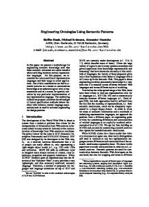
FIGURE 2. The component view on a physical system, showing a two-level part-of decomposition and the system topology for an air pump. Sub-components are drawn inside the area defined by their super-component. The small solid blocks are the interfaces through which components are connected.
sub-systems, which on their turn can be decomposed into more primitive components. $ Typical relationships: the various constituents of a system (sub-systems, components) are linked to one another through certain connections. For a physical system, this usually provides information on the spatial topology of the system, but in general, the connections indicate the paths for physical interactions between the constituents. An example of a structural-topological diagram for a physical system, i.e. an air pump, is shown in Figure 2. This structural view on physical systems is based upon what we call a component ontology. Our component ontology is constructed from mereology, topology and systems theory. In a separate ontology of mereology a part -of -relation is defined that formally specifies the intuitive engineering notion of system or device decomposition. This mereological ontology is then imported into a second separate ontology which introduces topological connections that connect mereological individuals. This topological ontology provides a formal specification of what the intuitive notion of a network layout actually means and what its properties are. The ontology of systems theory includes the topological ontology and defines concepts like (open or closed) systems, system boundary, etc., on top of it.
370
P. BORST ET AL.
1 define-theory mereology 2 define-class m-individual [x] a m-individual(x) , – . equal(x, x) 3 define-relation proper-part-of(x, y) a proper-part-of(x, y) – . not proper-part-of(y, x) b proper-part-of(x, y) and proper-part-of(y, z) – . proper-part-of(x, z) 4 define-relation direct-part-of(x, y) a direct-part-of(x, y) , – . proper-part-of(x, y) and not exists z: proper-part-of(z, y) and proper-part-of(x, z) 5 define-relation disjoint(x, y) a disjoint(x, y) , – . not(equal(x, y) or exists z: proper-part-of(z, x) and proper-part-of(z, y) 6 simple-m-individual(x) , – . m-individual(x) and not exists y: proper-part-of(y, x) FIGURE 3. Excerpt from the mereological ontology. This ontology defines the means to specify decomposition information and the properties any decomposition should have.
2.1 .1 . Mereology Our mereological ontology is simply an Ontolingua implementation of the Classical Extensional Mereology as described by Simons (1987). We therefore only give a brief explanation of this ontology and refer to (Simons, 1987) for the details and more philosophical aspects. Two relations define part-of decompositions. The relation equal (x, y) defines which individuals are to be considered mereologically equal. In the usual case, it only holds for equal(x, x) but in some situations it is convenient to say that two individuals are equal when they have the same parts. An individual x is a mereological individual when equal(x, x) holds. When a mereological individual x is a part of a mereological individual y, the relation proper-part-of(x, y) holds. With these relations it is possible to write down a variety of axioms specifying desirable properties any system decomposition should have. Examples are the asymmetry and transitivity of the proper-part-of relation. Figure 3 shows an excerpt from the mereological ontology. Definition 2 defines the class of mereological individuals that was sketched above. The definition of the proper-part-of relation clearly shows the asymmetry (3a) and transitivity (3b) axioms. Note that these definitions only serve as an illustration and are not meant to be complete. The ontology furthermore defines the relation disjoint(x, y) which holds for individuals that do not share a part and simple-m-individual, the class of individuals that have no decomposition. 2.1 .2 . Topology The topological ontology defines a relation to express the fact that mereological individuals are connected. We want to use this relation to define connections in the component view of a physical system, where being connected means being able to exchange energy. Because we have this application in mind, the topology must be capable of stating three things as follows. $ Express that two individuals are connected.
371
ENGINEERING ONTOLOGIES
1
define-theory topology
2
include-theory mereology
3 a
define-class connection(c) connection(c) < - > exists x, y: connects(c, x, y)
4 a b
define-relation connects (c, x, y) connects (c, x, y) - > connects (c, y, x) connects (c, x, y) - > not (part-of (x, y) or x +y part of (y, x)) connects (c, x, y) and part-of (x, z) and disjoint (z, y) - > connects (c, z, y)
c
x,y
+ z x
x1 c y1 c x2 y2
y c y2
x2,y1 connects (c, x1, y1) and connects (c, x2, y2) c+ x1 + - > not (disjoint (x1, x2) and disjoint (x1, y2)) FIGURE 4. Excerpt from the topological ontology. This ontology provides the means to express that individuals are connected. Axioms ensure that only sound connections can be made. These axioms take into account the possible part-of decomposition an individual can have.
d
$ Multiple connections between components must be possible. $ It must be possible to say that a connection is of a certain type. A well known way of expressing topological information is described by Clarke (1981). He introduces a relation Cx , y to express that individuals x and y are connected. Unfortunately, given this relation, it is only possible to express that there are two connections between two individuals when connections are regarded as a special kind of individuals themselves. We find this point of view debatable, because a physical connection can be a point of contact (mechanical, electrical), an area crossing a volume flow (hydraulical, pneumatical) or even something abstract as a field (electro-magnetic). We have therefore introduced connections as a relation between individuals and reified the relation into the connection concept to allow for multiple connections that can be typed. This has led to the relation connects(c, x, y) which means that individuals x and y are connected by connection c (see Figure 4). The projection performed in this ontology is of the type include and extend. Inclusion is done in line 2 and the extension takes shape by definition of new concepts and relations that use mereology in their axioms. This yields an ontology that has the same level of abstraction as the included mereology. There are three axioms concerning connections. The symmetry of the connection relation is expressed by axiom 4a. Axiom 4b prohibits that a part is connected to itself or its whole (part-of(x, y) holds iff x is a proper part of y or they are equal). The third axiom (4c) ensures that when a part whose whole is disjoint with an individual connected to the part, the whole is also connected to that individual. The fourth axiom (4d) prohibits a connection to connect two entirely separated pair of individuals. This also excludes connections that fork. 2.1 .3 . Systems theory On top of the topological ontology the standard system-theoretic notions such as system, sub-system, system boundary, environment, open / closedness, etc., can be defined. Some of these definitions can be found in Figure 5. The ontology projection is of the include and extend type, just like in the topological ontology. Definition 3 states that a system is a mereological individual (but not every
372
P. BORST ET AL.
1 define-theory systems-theory 2 include-theory topology 3 define-class system(s) a system(s) – . m-individual(s) 4 define-relation in-system(x, s) a in-system(x, s) , – . proper-part-of(x, s) and system(s) and not system(x) 5 define-relation in-boundary(c, s) a in-boundary(c, s) , – . connection(c) and system(s) and exists x, y: connects(c, x, y) and in-system(x, s) and not in-system(y, s) 6 define-relation subsystem-of(sub, sup) a subsystem-of(sub, sup) , – . system(sub) and system(sup) and proper-part-of(sub, sup) 7 define-class open-system(s) a open-system(s) , – . system(s) and exists c: in-boundary(c, s)
FIGURE
8 define-class closed-system(s) a closed-system(s) , – . system(s) and not open-system(s) 5. Excerpt from the systems theory ontology. This ontology introduces system-theoretic notion on top of the topological ontology.
mereological individual is a system). The (in-system(x, s) holds for individuals that are in the system and are not sub-systems of it. This is different from the subsystem-of(sub, sup), where the part must be a system. A connection is in the boundary of a system when it connects an individual in the system to an individual outside the system. With this definition, the classes open-system and closedsystem can be defined easily. 2.1 .4 . Components After the ontology inclusion and extension of the previous paragraphs, now a more complex projection will be presented, i.e. the projection of the abstract systems theory ontology to the component ontology. The component ontology defines the structural view on physical systems engineers have as depicted in Figure 2, i.e. components that can have sub-components and terminals. The terminals are the interfaces of the components to the outer world. Therefore, connections hook onto terminals instead of components. This interpretation of components and connections is a bit more complex than the networks of abstract individuals and connections in systems theory. Nevertheless, the definition of these concepts can be kept simple due to a projection of the abstract systems theory on the definitions of engineering components and connections, thus enforcing the components to comply to the rules of systems theory. The paragraph below describes the way this projection takes place. Because this projection makes abstract concepts more specific, this type of projection is called include and specialize . Figure 6 shows some definitions from the component view ontology. The
ENGINEERING ONTOLOGIES
373
1 define-theory component-view 2 include-theory systems-theory 3 define-class component(c) a component(c) – . m-individual(c) 4 define-relation comp. subcomp(c, s) a comp. subcomp(c, s) , – . component(c) and component(s) and direct-part-of(s, c) 5 define-relation conn. term(conn, term) a conn. term(conn, term) and comp. term(comp1, term) – . exists comp2: connects(conn, comp1, comp2) b component(comp1) and component(comp2) and connects(conn, comp1, comp2) – . exists term: conn. term(conn, term) and comp. term(comp1, term) 6 define-class phys-system(s) a phys-system(s) , – . system(s) and (in-system(c, s) – . component(c)) FIGURE 6. Excerpt from the component ontology. This ontology formalizes the component view of engineers on physical systems. Note that the ontology can be kept relatively simple because systems theory is projected onto it.
important classes are the classes component, terminal and physical-system. The relations comp.subcomp, comp.term and conn.term relate components to their sub-components, terminals to components and connections to terminals. Only the definitions contributing to the ontology projection are shown in the figure. Ontology projection consists of inclusion (line 2) and the definition of axioms that specify the abstraction of components to system theoretical concepts. Definition 3 shows how the ontological commitments for abstract mereological individuals are projected onto components. Definition 4 defines the meaning of the comp.subcomp relation in terms of mereology. The projection of topological connections onto component connections is performed by definition 5. Definition 6 defines the modelled device as a system of components. The fact that connections can be of a certain type has been left out of the excerpt to keep it easy to understand. 2.2. PROCESS ONTOLOGY
Our physical process ontology specifies the behavioural view on physical systems. In the general case it is quite difficult to formalize what the notion of a dynamic process precisely entails. Fortunately, for a certain part of physics this has been done to a level where one can define really primitive process concepts. The approach we take here is known in engineering as system dynamics theory, which also forms the theoretical background of the bond graph method (Karnopp, Margolis & Rosenberg, 1990). The basic idea behind this theory is that the dynamics of a system can always be captured by looking at the change of different kinds of stuff. This change of stuff is also called flow. For instance, in electrical systems, dynamic behaviour consists of the change of electrical charge , i.e. electrical current. Likewise, in the mechanical domain the stuff is called location and change of location is y elocity. The thing required to bring about a flow is called effort. Table 1 lists the types of stuff, flow and effort of some of the physical domains defined in the ontology.
374
P. BORST ET AL.
TABLE 1 Some examples of physical domains. In each domain , dynamic behay iour is described as flow , i.e. change of stuff. Effort is that what is required to bring about a flow Domain
Stuff
Flow
Effort
Electrical Mechanical Hydraulical
Charge Location Volume
Current Velocity Volume flow
Voltage Force Pressure
The interesting aspect about this table is that the product of a flow with its related effort has the dimension energy / time , i.e. such a pair defines an energy flow. Physical behaviour can therefore be defined in terms of energy flows. The process ontology introduces physical mechanisms which are applications of physical laws or principles to one or more energy flows. An important feature of these mechanisms is that they exploit in detail the analogies that exist between different physical domains. For example, the principle of conservation of momentum in mechanics is analogous to induction in the electrical domain. Many more of these analogies exist. This approach is valid for standard classical, deterministic physics, covering such diverse fields as mechanics, electricity and magnetism, hydraulics, acoustics, and thermodynamics. Complex process descriptions can be formed by making a network of mechanisms, linked by energy flows. This abstraction is used to construct the process ontology. The process ontology includes systems theory and specializes the system theoretic concepts to processes. Just like the component ontology, the process ontology defines relatively simple concepts and relations onto which the system ontology is projected. This can be seen in Figure 7. Mechanisms are defined as simple 1 define-theory process-view 2 include-theory system-theory 3 define-class mechanism(m) a mechanism(m) – . simple-m-individual(m) 4 define-class energy-flow(ef) a energy-flow(ef) – . connection(ef) 5 define-relation ef. from-to(ef, f, t) a ef.from-to(ef, f, t) – . not ef.from-to(ef, t, f) b ef.from-to(ef, f, t) – . connects(ef, f, t) c energy-flow(ef) and connects(ef, x, y) – . ef from-to(ef, x, y) or ef.from-to(ef, y, x) 6 define-class process(p) a process(p) , – . ystem(p) and (in-system(m, p) – . mechanism(m)) FIGURE 7. Excerpt from the process ontology. This ontology formalizes a large part of physics. It defines how process descriptions can be formed by making a network of domain-independent mechanisms and energy flows. The ontology is relatively simple because systems theory is used for the definition of the networks.
375
ENGINEERING ONTOLOGIES
Connectivity type
Effort/flow
Domain (e.g. el, me)
Effort-source
Voltage-source Force source
Flow-source
Current-source Velocity-source
Stuff–store
Capacitor Spring
Action-store
Inductance Mass
Source
One-port
Store
Resistor Friction
Dissipator
Mechanism
Two-port
Multi-port
Transformation
Transformer Lever
Gyration
Voice-coil Gyrator
Effort-distributor
Parallel-connection Same-force
Flow-distributor
Series-connection Same-velocity
Convertor
Distributor
FIGURE 8. The taxonomy of physical mechanisms. The properties discriminating between the classes after branching are printed above the branch points. The classes on the right give some examples of mechanisms in the electrical and mechanical domain.
mereological individuals. Energy flows, which have a certain direction, flow from one mechanism to another. The projection is performed by stating that an energy flow is a topological connection that connects the two mechanisms. A process description can now simply be defined as a system of mechanisms. The definition of physical domains as depicted in Table 1 is not shown in Figure 7. Figure 8 shows the taxonomy of mechanisms as defined in the process ontology. The classes in the figure are present as classes in the ontology and class – sub-class relations are defined for every line in the figure. The discriminating properties used to construct this taxonomy are the number of energy flows linked by a mechanism (connectivity), the mechanism type, whether effort or flow plays the most important role with respect to the mechanism type and the physical domain (e.g. mechanics, electricity, hydraulics, thermodynamics). Note that some discriminating properties are not useful for certain types of mechanisms. The order in which the discriminating properties are applied here is the opposite of the order used in the typical engineering education. There, the distinction between physical domains is made first: there are separate courses in mechanics, electrical engineering and thermodynamics. Only when students have mastered all courses, they are able to see the analogies between the domains that makes the process ontology as compact and elegant as it is. 2.3. MATHEMATICAL ONTOLOGY
The mathematical ontology defines the mathematatics required to describe physical processes. The EngMath ontology (Gruber & Olsen, 1994), available in the Ontolingua ontology library, is perfectly suited for this job and has therefore been (re)used for this. In this section, only a very short description is given that should be sufficient to understand the projection of the process ontology onto mathematics. For detailed information on EngMath see Gruber and Olsen (1994).
376
P. BORST ET AL.
The EngMath ontology formalizes mathematical modelling in engineering. The ontology includes conceptual foundations for scalar, vector and tensor quantities, physical dimensions, units of measure, functions of quantities, and dimensionless quantities. A physical quantity is a measure of some quantifiable aspect of the modelled world characterized by a physical dimension such as length, mass or time. Quantities in the EngMath ontology can be expressed in various units of measure , e.g. metre, inch, kilogram, pound, etc. the ontology defines all relations between quantities, units of measure and dimensions. A special class of physical quantities are time -dependent quantities. These are in fact continuous functions from a quantity with the time dimension to another physical quantity, and can therefore be interpreted as dynamic quantities, varying over time. Another important EngMath class for the PHYSSYS ontology are the Ontolingua (KIF) expressions that serve as a meta-level description of mathematical relations between physical quantities. For instance, a relation r between two time-dependent physical quantities x and y can be defined as: define-relation r(x, y) r(x, y) ï x52 p y Here, the expression x52 p y is the (infix form of the) Ontolingua expression used to define the EngMath relation r. In the PHYSSYS ontology, two time-dependent physical quantities are used to mathematically describe an energy flow and relations similar to r define the mathematical relationships between these quantities. 2.4. ONTOLOGY PROJECTIONS
The PHYSSYS ontology is an ontology that only performs ontology projections. It includes the component, process and EngMath ontologies and relates them to each other. Figure 9 shows the relations between instantiated views on a physical system. Basically, it defines that components are the carriers of physical processes that can be mathematically described with physical quantities and mathematical relations.
f
e
r(e,f)
Component ontology
Process ontology
Component
Mechanism
Terminant
Energy-flow
EngMath e,f Quantities r(e,f) Relation
Connection Process FIGURE 9. Interdependencies between the component, process and mathematical ontologies. Roughly it states that a component is the carrier of physical processes that are described by mathematics.
ENGINEERING ONTOLOGIES
377
1 define-theory PhysSys 2 include-theory component-view 3 include-theory process-view 4 include-theory EngMath 5 define-relation comp. proc(c, p) a component(c) and simple-m-individual(c) – . exists p: process(p) and comp. proc(c, p) b mechanism(m) – . exists c,p: process(p) and in-system(m, p) and comp. proc(c, p) c comp. proc(c1, p1) and comp. proc(c2, p2) and c1!5c2 – . disjoint(p1, p2) 6 define-relation conn. ef(c, ef) a conn. term(c, t1) and conn. term(c, t2) and comp. term(c1, t1) and comp. term(c2, t2) and comp. proc(c1, p1) and comp. proc(c2, p2) – . exists ef: conn. ef(c, ef) and in-boundary(ef, p1) and in-boundary(ef, p2) b energy-flow(ef) and process(p1) and in-boundary(ef, p1) and comp. proc(c1, p1) and process(p2) and in-boundary(ef, p2) and comp. proc(c2, p2) – . exists c: comp. term(c1, t1) and conn. term(c, t1) and comp. term(c2, t2) and conn. term(c, t2) FIGURE 10. Excerpt from the first part of the PHYSSYS ontology where components are projected onto physical processes. This is an example of an ontology that only contains formalizations of the interdependencies between the viewpoints it includes.
2.4 .1 . Components to processes Figure 10 shows the first part of the PHYSSYS ontology that includes the three viewpoints (lines 2, 3 and 4) and relates the component and process views (definitions 5 and 6). The relation comp. proc (definition 5) implements the projection of simple components to process descriptions. Axiom 5a states that every atomic component must have a process description and axiom 5b that each mechanism must be part of the process description of a component. Axiom 5c ensures that a mechanism can only be part of one process description of one component. The fact that energy flows between process descriptions of two components must go through a connection is expressed by definition 6. For each connection between components, the process descriptions of these components must interact via an energy flow (axiom 6a). Vice versa, axiom 6b defines that an energy flow between the process descriptions of two components goes through a connection. Note that the relationship between the type of a connection and the number and domain of the energy flows of this connection has not been included in the excerpt. 2.4 .2 . Processes to EngMath Mapping of the process ontology to EngMath is depicted in the right-hand side of Figure 9. Informally, the mapping states that for each energy flow there are two time-dependent physical quantities, one for the effort and one for the flow. The domain of the energy flow determines the dimension of the quantities. For instance, an electrical effort quantity has the dimension energy/electrical-current
378
P. BORST ET AL.
7 define-relation mech.mathrel(m, r) a dissipator(m) and ef. from-to(ef, n, m) and ef. effortq(ef, e) and ef. flowq(ef, f) – . exists r: mech. mathrel(m, r) and forall t: value-at(e, t)5et and value-at(f, t)5ft – . r(et, ft) and (et p ft . 50 p energy-dimension) and zero-quantity(et) , – . zero-quantity(ft) FIGURE 11. Excerpt from the second part of the PHYSSYS ontology where physical processes are projected onto mathematical relations. This is an example of a domain ontology that only contains formalizations of the interdependencies between the viewpoints it includes.
(voltage) and the flow quantity the electrical-current dimension. For each mechanism there is a mathematical relation that relates the values of the physical quantities of the energy flows connecting the mechanism to each other. The mapping also imposes constraints on the relation. These constraints only depend on the mechanism type and they are independent of the domains of the energy flows. The mathematical relation in Figure 9 belongs to a dissipator mechanism. The constraints on such a relation are that it is a continuous function r : e S f that lies in the first and third quadrant and that r (0) 5 0. For an electrical energy flow, this can be an instantiation of Ohm’s law V 5 I 3 R whereas in the mechanical domain it can model some kind of friction with F 5 k 3 y . Figure 11 shows an excerpt of the second part of PHYSSYS, the part that performs the process to mathematics projection described above. Only a part of the definition of the relation mech.mathrel, the relation that relates a mathematical relation to a process, is shown. Axiom 7a states that for every dissipator a relation between the effort and flow quantities of the energy flow to the dissipator must exist. In the axiom the relations ef.effortq and ef.flowq are used. These relations link each energy flow to physical quantities for the effort and the flow. Axioms not incorporated in Figure 11 ensure that these quantities have the proper physical dimension. The constraints on the relation for dissipators have been formalized by stating that the effort is zero if and only if the flow is zero and that the product of effort and flow, i.e. the energy flow, must be positive. In other words, the dissipator must dissipate energy. Furthermore, it is probably needless to say that PHYSSYS contains axioms like axiom 7a for each type of mechanism defined in the process view. 2.5. SUMMARY
In developing the PHYSSYS ontology we found that constructing an ontology from smaller ontologies leads to an ontology that because of its structure is easy to understand and well suited for reuse. Three types of ontologies have been distinguished as follows. (1) ‘‘Super’’ theories which are general and abstract ontologies such as mereology, topology, systems theory. (2) Viewpoint or base ontologies that formalize a conceptual category of concepts in a domain. For the physical domain at least three of such categories exist: of a configuration of components, physical processes underlying behaviour and the engineering mathematics that is used to describe the processes. (3) Domain ontologies that form an integral and coherent conceptualization of a
379
ENGINEERING ONTOLOGIES
domain. The conceptualization of the domain of physical systems offered by PHYSSYS is nothing other than a combination of the three viewpoints plus the formalization of the interdependencies between the concepts in different viewpoints. To construct a large ontology from smaller ontologies, the dependence between concepts and relations in different ontologies are formalized as ontology projections. Three types of ontology projections were used and are named according to the way they can be implemented. (1) Include and extend: an imported ontology is extended with new concepts and relations. The result has the same level of abstraction as the included ontology. An example is the extension of mereology to topology that was described in this section. (2) Include and specialize: an abstract theory is imported and applied to the contents of the importing ontology. Doing this, abstract concepts are specialized. An abstract ‘‘super’’ theory can be considered generic when there are many useful specializations that can be made. For instance, systems theory is used twice in PHYSSYS. It is used as an abstraction of system components as well as an abstraction of physical process descriptions. (3) Include and project: different viewpoints on a domain are joined by including the views in the domain ontology and formalization of their interdependencies. In contrast to the previous ontology projections, these projections contain a great deal of domain knowledge and can therefore be considered to be ontologies of their own.
3. The OLMECO library In the previous section an ontology was presented that describes what physical models should look like. In this section we will first examine the way in which such a model is constructed by an engineer. This provides us with the information about what kind of data a model library should contain to support engineers. The remainder of this section will describe the OLMECO model library that has been designed to conform to these observations. 3.1. EVOLUTIONARY MODELLING
The explicit separation between conceptual levels (Top & Akkermans, 1994) described in Section 2 defines a way of organizing models which is different from the traditional approach, and it is depicted in Figure 12. Here, each ontological
Component level
Alternative decompositions
Process level
Alternative processes
Mathematical level
Alternative relations
Model FIGURE 12. Modular structure of a model composed from model fragments in an engineering library, based on the separation of ontological viewpoints. The arrows indicate links to alternative model fragments in the library that are available to revise the model.
380
P. BORST ET AL.
viewpoint corresponds to an information layer which has a strong internal cohesion and a relatively narrow coupling with other layers. The left part of the figure shows a physical model of the kind described by PHYSSYS. Arrows indicate the relationship between parts of the model and the model fragments in the library they can be chosen from. When modelling in a top-down manner, first components will be identified, since they are linked to the ‘‘real’’ objects, more or less independent from physical processes considered. Components are decomposed into sub-components until the internal layout of the sub-components becomes irrelevant. Next, at the conceptual – physical level for each component the assumed physical concepts or processes are described. This description is independent of the internal layout of the components, but does depend on the underlying physical assumptions made. Finally, the resulting mathematical equations are specified and processes for computer analysis and simulation. Once a fully instantiated model has been constructed, the result can be assessed by means of analysis of the model or the simulation data derived from the model. This may lead to the conclusion that the model, or parts of the model are inadequate. In such a case, the modeller will revise the model by choosing alternative model fragments from the library for parts of the instantiated model. The model granularity can be changed by choosing alternative decompositions, alternative process descriptions may contain additional secondary physical processes that were neglected first and alternative relations may be non-linear instead of linearized. This approach to structured engineering modelling is depicted in Figure 13; an associated modelling support system prototype called QuBA has been developed and is described by Top and Akkermans (1994). Each ontological level goes with its own characteristic questions that have to be answered by the modeller as follows. $ Component level: out of which concrete artifacts (device components) does the system that is to be designed exist, and how are they interconnected (system structure or layout)? $ Process level: how is the behaviour of the system components realized in terms of physical mechanisms?
Modelling
Component model
Modelling
Query and observations
Process model
Modelling
Mathematical model
FIGURE 13. Evolutionary approach to physical modelling, with task decomposition based on ontological differentiations.
ENGINEERING ONTOLOGIES
381
$ Mathematical level: how is the physical behaviour formally specified in terms of equations, such that system analysis and simulation can be carried out by computer? Thus, in practice it will be quite evident during the modelling process what to put on what level, and when to transit from one level to another. Given the modelling decisions described above, a model library should contain the following kinds of model fragments. $ A sufficient number of top-level components to support modelling in a certain domain and facilities like a taxonomy to help the modeller to find the right components. $ Different options for decomposition of the top-level components into smaller ones. $ Different physical process descriptions that are possible for a component. Usually, these descriptions have in common that they model one primary physical process and are only different in the secondary processes that are modelled. $ A physical process can often be described by different mathematical relations. Which one has to be chosen often depends on structural properties or the operating conditions of the modelled system. The library must therefore contain relations for each situation. In the next sections, the general structure of the library will be explained by following the conceptual schema that was used as the basis for the implementation of the library. Model fragments from the thermodynamic domain will be presented as an illustration.
3.2. STRUCTURE OF THE LIBRARY
The above discussion represents a knowledge-level analysis of what engineering modelling and design actually ‘‘is’’. In this section we will discuss how some of these aspects are being practically implemented in the OLMECO library for models of mechatronic design components. The core of the OLMECO software is a conventional (OO / relational) database for storage and retrieval of mechatronic model fragments; we will give an impression of its structure by considering the most important parts of the Conceptual Schema of the database. For more details, see Top, Breuriese, van Dijk, Broenink and Akkermans (1994) and for some examples of its use see also Top, Breunese, Broenink and Akkermans (1995b ). The OLMECO conceptual schema has been represented with the object-oriented modelling technique, called OMT, of Rumbaugh, Blaha, Premerlani, Eddy and Lorensen (1991). The basic structure of the OLMECO library is shown in Figure 14. It can be seen that the library structure follows the differentiation between ontological aspects, as discussed in the previous section. It is noteworthy that there are three different points, indicated by the alt - ? ? ? links, where the user can make separate modelling choices. Systems can be decomposed in different ways, functions of which device components are the carrier can be realized by different physical processes, and physical processes can be specified by different mathematical
382
P. BORST ET AL.
refined-by (alt-decomps) Decomposition structure
Component kind-of
part-of
Component level refined-by
(alt-processes)
Process description
part-of
Physical mechanism
Process level refined-by
(alt-relations)
Mathematical relation Mathematical level FIGURE 14. The general conceptual schema of the OLMECO library. It defines the database structure of the library and reflects .e PHYSSYS ontology. Rectangular boxes denote entity types or classes. Solid line connections, possibly with a diamond symbol carrying the relation name, stand for relations. Open and solid circles indicate the cardinality of the relation to be zero or one (optional association) and zero or more (one-to-many association), respectively. The triangle symbolizes the is-a or kind-of relationship (generalization / specialization), while the small diamond is employed for the part-of relationship (aggregation). Dotted lines are used to indicate constraints on / between entities or relations.
constraint expressions. Similar suggestions for structuring the modelling process not only come from AI, but are also proposed in the engineering literature (de Vries, Breedveld & Meindertsma, 1993). The proposed generic structure of the OLMECO library has the following two important advantages. (1) It separates different groups of modelling decisions, thus giving handlers for user support and facilitating a piecemeal approach to engineering model construction. (2) It provides a breakdown of stored models into parts that have a generic nature, thus enhancing reusability and sharability of library models. 3.2 .1 . Component taxonomy A component taxonomy can be stored in the library by means of the kind-of generalization / specialization relationship in Figure 14. This information can be used by the modeller to quickly access the components he or she wants to use. Figure 15 shows the taxonomy of the thermodynamic library. For the components on the right, decompositions and / or process descriptions are available. Note that because the component taxonomy is meta-level information about components in instantiated models, the PHYSSYS ontology did not contain a formalization of it. The keywords printed in italics on the right provide another way to index the library. The idea is that these keywords provide the link between specific
383
ENGINEERING ONTOLOGIES
Heated space (room)
Thermal store
Thermal barrier (wall, radiator) Thermal connector
Thermal component
Thermal souce
Thermal fluid line
Pipe Pipe with ext. cond. (heat exch. pipe, radiator) Pump
Thermal fluid flow controller
Two-way valve (valve) Controlled splitter (valve) Controlled mixer (valve)
Thermal fluid junction
Splitter Mixer
Heat exchanger
Recuperative heat exchanger Regenerative heat exchanger
Conduction source
Heat source (heater) Heat sink (atmosphere)
Convection source
Convection heater (boiler) Convection heat sink (atmosphere) Closed system heater (boiler)
FIGURE 15. Taxonomy of thermal components. This taxonomy allows the modeller to quickly find components in the library. The library contains component models for the components on the right. Keywords printed in italics annotate specific situations in which a generic library component can be used, thus providing an alternative way to access components in the library.
component names used in the thermodynamic domain and the generic model components stored in the library. The keywords wall and radiator are examples of this. Both heat flow through the metal of a radiator and heat flow from one side of a wall to the other can be modelled with the thermal barrier component. For large libraries like the OLMECO library, the component taxonomy also becomes very large. A picture like the one in Figure 15 containing the model components of all OLMECO participants contains over 250 components and covers 16 pages! This shows that the taxonomy browsers in the library software must be able to cope with large amounts of components and be able to present parts of this taxonomy in a clear way to the user. 3.2 .2 . Decomposition structure In physical modelling two types of decomposition can be distinguished. One type is the decomposition of components in pure physical sub-components. An example of this is the decomposition of a closed system heater in Figure 16. A closed system heater is a device to heat circulating water. In the domain of thermodynamic systems, closed system heaters may, or may not include a pump that causes this circulation of the water. This has led to the three decompositions in the figure. A second kind of decomposition establishes that physical models can be modelled more accurately. Because of the way physical processes are described, objects can only have a single value for state quantities like for instance temperature. This means that every part of for example a wall, is assumed to have the same temperature, instead of the continuous temperature distribution it has in reality. To approximate the real situation more accurately, the wall can be mentally decomposed into a number of wall segments which all can have a different temperature.
384
P. BORST ET AL.
Heat source
Heat source
out
out
ext in
ext
Pipe with external conduction out in
Pipe with external conduction out in
Pump out
in
in
out
(a)
out
(b)
Heat source out
ext in
Pipe with external conduction out in
Pump in
out
out
(c) FIGURE 16. Decompositions of a closed system heater.
This way, the continuous distribution will be approximated by a stepwise distribution. To facilitate this kind of decomposition, the library contains decompositions like the one in Figure 17. The most apparent difference between the OLMECO library structure and PHYSSYS is that the first contains decomposition structures. In PHYSSYS it was sufficient to associate sub-components to their parent with the comp-subcomp relation. For the library however, the relation between a generic component and all alternative ways for decomposition must be stored. Therefore, the concept of a decomposition was introduced. Thus, the association between a component and a possible subcomponent is made in two steps: first from the component to a possible decomposition structure (alt-decomp) and then from this decomposition structure to the sub-component by a part-of relation.
Thermal conductor in
in
Thermal conductor out
in
out
FIGURE 17. A possible decomposition of a thermal conductor.
out
385
ENGINEERING ONTOLOGIES
C
tp 0
C
1
tp
tp 0
Sf
hy
1
1
tp
Sf
hy
hy
1
hy
R I R FIGURE 18. Bond graph process descriptions of a hot water flow through a pipe. A bond graph is a graphical representation of the process ontology as formalized in PHYSSYS. The nodes represent physical mechanisms of different kinds which are connected by energy flows. Both process descriptions model heat convection, whereby (b) contains an additional, secondary effect (the I node) due to the inertia of the water.
3.2 .3 . Physical description Figure 18 shows two process descriptions that can be used to model a pipe component. These processes are presented in a graphical way using bond graphs. Bond graph representations are used in the modelling tool to display process descriptions in the library and as a way for the modeller to construct and edit instantiated process descriptions graphically. In a bond graph, the nodes represent physical mechanisms connected by half arrows called bonds which represent energy flows. The nodes are mnemonics indicating the type of the mechanism they stand for. A C node (short for capacity) for instance, indicates a store of stuff. Table 2 lists all bond graph nodes and the corresponding mechanisms. Full arrows in the bond graphs represent information flows which have not been formalized yet in PHYSSYS. Usually, the only difference between the process descriptions that model a library TABLE 2 This table lists the bond graph nodes and the names of the mechanisms they represent. The nodes are mnemonics for the entries in the third column of the table Node Se Sf C I R TF GY 0 1
Short for Source of effort Source of flow Capacity Inertia resistance Transformer Gyrator — —
Mechanism Effort source Flow source Stuff store Action store Dissipator Transformation Gyration Flow distributor Effort distributor
386
P. BORST ET AL.
component are the secondary physical processes that are included. The process descriptions in Figure 18 for example, both model the cony ection and hydraulic resistance processes. The description on the left does not include hydraulic inertia (the process that makes your water pipes at home bang when you close the tap abruptly) whereas the one on the right-hand side does. This can easily be seen by the fact that the process description on the right includes an additional l-node. The relation between components and the process descriptions that model their behaviour can be found in the conceptual schema as the alt-processes relation that crosses the boundary between the component level and the physical process level. Note the analogy between this relation and the comp.proc relation in PHYSSYS. The difference is that in PHYSSYS the relation is between a component and one process description that models the component whereas alt-processes associates all alternative process descriptions to a generic component. 3.2 .4 . Mathematical description For a number of reasons, a physical mechanism can be described mathematically in numerous ways. These reasons have been listed below, with examples from the thermodynamic domain. Some of the examples below concern the relations for hydraulic resistance (the R element in Figure 18). These relations can be found in Figure 19). The reasons for different mathematical relations are as follows. (1) Domain and nature of the process: hydraulic friction requires relations different Hydraulic resistance p 5j Re 5
1 r V 9 uV 9u di 2A2f
(1)
V 9di V 9di r 5 … Af hAf
(2)
Af 5 1–4 π d 2i Smooth pipe surfaces
j5
E
64 Re 0.3164
Re , 2300 (4)
3000 , Re , 105
4
4Re 0.00540 1
(3)
0.3964 Re 0.3
2 ? 104 , Re , 2 ? 106
Rough pipe surfaces
j5
E
64 Re
Re , 2300 ,
1 (2 ? 10 log [di / K ] 1 1.14)2
fully turbulent flow
K # 0 .07
FIGURE 19. Some examples of mathematical relations that can be used to describe hydraulic resistance.
ENGINEERING ONTOLOGIES
387
from those for mechanical friction. Different kinds of mechanical friction are described by different formulas. (2) Geometric and material properties of the modelled system: the relation for hydraulic friction in pipes with a smooth surface is different from the relation to be used in case of a rough surface (see Figure 19). (3) Operating conditions of the model: when the volume flow of water becomes higher, the nature of the water flow changes from laminar to turbulent. Hydraulic resistance for laminar flows is described differently compared to resistance in the turbulent case. This can be seen in Figure 19 where the Reynolds number Re quantifies the degree of turbulence. The simulator should check whether all relations are used in their range of validity and stop in case of a violation. Ideally, the violated relation could be replaced and simulation resumed. (4) Mathematical simplifications: the numerical simulation algorithm used may pose restrictions on the mathematical relations. This may require, for instance, linearizations of equations around a certain working point. In these cases, the same consideration for the validity of linearized relation holds as the one for the operating conditions mentioned above. It is important to realize that all relations for a mechanism must conform to the constraints imposed upon them by the projection of physical processes onto mathematical relations defined in PHYSSYS. The ontology does not define the exact relation to be used, but only says what class of mathematical relations it must belong to. In theory, the library software could check these constraints, but to be able to check all possible relations requires powerful computer algebra. In the conceptual schema of Figure 14, one or more mathematical relations are linked to a mechanism by the alt-relations relation crossing the line between the physical process level and the mathematical level. The difference with the mech.mathrel relation in PHYSSYS again is that in an instantiated model a mechanism is described by a single relation but a generic mechanism can be described by one of many relations. 3.3. INSTANTIATED MODELS
Software to support the modelling of physical systems consist of three main parts: a model library , a modelling tool and a simulator. The model library software allows the modeller to browse through the library and select the appropriate model fragments. The selected model fragments can then be assembled into an instantiated model using the modelling tool. Output of the modelling tool is the set of (differential) equations describing the behaviour of the modelled system. The simulator can accept these equations together with parameter values and arguments for the simulation algorithm (such as step sizes) and compute a simulation which predicts the behaviour. Up to now, only the general relationships that can exist between library model fragments were discussed. The situation is slightly different when we consider the user-built application models the modelling tool works with, since they represent an assembly of instantiations of generic model fragments. An instantiated model is a
388
P. BORST ET AL.
Parameter information
part-of
Instantiated model
Management information has
label part-of refined-by (comp.proc) Process description
Component partof Decomp structure
{leaf} {NOT both} refined-by (comp.decomp)
Mathematical relation
part-of
Physical mechanism
refined-by (mech-mathrel)
FIGURE 20. User-constructed instantiated models in the OLMECO library.
model constructed by an individual user or user group in the context of a specific application. The conceptual schema of an instantiated model is given in Figure 20. It contains references to the three different levels: (i) it identifies a selected component and the selected part-of hierarchy; (ii) it gives a set of bond graphs that collectively provide the physical description of the selected component, (iii) it gives a set of mathematical descriptions that describe the behaviour of each of the associated bond graph elements. Moreover, an instantiated model contains (iv) parameter information. Note that the lower part of Figure 20 could almost serve as a conceptual schema of the PHYSSYS ontology. The only exception is the decomposition structure, which was introduced in OLMECO to store alternative decompositions and, for practical reasons, is also used in instantiated models. In instantiated models, it is completely equivalent to PHYSSYS’ comp.subcomp relation. In order to appreciate the differences between an instantiated model and the generic building blocks of the library, it is helpful to compare the schema of Figure 20 with Figure 14. Whereas the generic library fragments allow one-to-many refinement links—representing multiple modelling alternatives—instantiated models only contain one-to-one links corresponding to the specific selection made among alternatives. Furthermore, it is possible to have instantiated models that do not contain certain layers of information (see the solid balls in the schema). This is important to provide flexibility for the end user and to enhance interoperability with external software. Namely, instantiation can be partial, e.g. if not all parameter data in the mathematical descriptions are specified. What type of instantiation is needed, depends on the requirements and capabilities of the external tools. Strictly speaking, for mathematical and computational purposes (analysis and simulation) only the mathematical description would be needed, and the component and / or physical levels of the model might be left empty. According to the conceptual schema, this constitutes a legal instantiated model—although perhaps not a preferred one from the viewpoint of structured modelling and sharability of models. (Note that even
389
ENGINEERING ONTOLOGIES
Modelling assumptions
part-of
Management info
part-of
Validation info
part-of Version
Responsibility
Publicness
User advice
FIGURE 21. Model management information in the OLMECO library.
the empty model represents a legal instantiated model.) This guarantees the interoperability with the external tools working with the library. For example, the OLMECO conceptual schema makes it even possible to work with simulation tools that do not know anything about components and bond graphs (e.g. ACSL or other Fortran-based mathematical software). All other information about components and bond graphs then provides confidence building documentation that can be used to backtrack the model construction process and to find suitable alternatives. Components, decomposition structures, conceptual physical descriptions and mathematical descriptions know by which instantiated models they are used. Furthermore, each instantiated model has a user-definable label or keyword. This provides an important search facility. Finally, end user requirements with respect to the library have clearly pointed to the need for handles for knowledge management in sharing and reuse. Figure 21 shows a schema for this kind of information in the OLMECO library. The management information attributes; version, responsibility and publicness, represent quite straightforward database administration aspects. Version contains the information about which version of the model one is dealing with, and possibly about how and why the model has become what it is (the revision or update history). Responsibility refers to the owner(s) or administrator(s) who is / are responsible for the stored model information. The publicness attribute yields the status of the model as, say, a generally accepted one (within the user organization) or as a private ‘‘exercise’’. This attribute might be used to introduce certain quality levels with respect to models and their degree of validation. User ady ice contains miscellaneous comments for using the model (such as hints for simulation algorithms or step sizes in tricky cases). There are two management information elements that deserve special mention, because they contain crucial meta-level information regarding model construction and use. (1) Validation information: any information that explains how the model has been or can be validated: literature references, measurement data, etc. (2) Modelling assumptions: the conditions under which the model is (not) applicable. Both are very important attributes, that will need further attention in the future. Currently, the modelling assumptions and validation information are simply given in textual format, and thus comprise qualitative annotations concerning the model.
390
P. BORST ET AL.
Ideally, however, this meta-level information should be formalized in such a way that a support system for engineering modelling could actually reason about it. Steps in this direction have been made by Addanki, Cremonini and Penberthy (1991) in the so-called GoM approach and more recently by Pos, Akkermans and Top (in press). The GoM approach, contains some of this meta-level information, albeit in hard-wired form. Pos et al. (in press) present a classification of goals and demands on a model. The 007 model revision KBS based on this theory can determine whether an instantiated model actually has the required properties or whether there is a discrepancy. For some discrepancies, the system uses validation information and modelling assumptions to automatically solve the problem by replacing fragments of the instantiated model by alternative model fragments from the library.
3.4. SUMMARY
This section described the way the formalization of physical models in the PHYSSYS ontology has been used to develop the conceptual database schema of the OLMECO library, containing reusable model fragments, especially tuned to an evolutionary modelling process. The library contains different types of model fragments: generic components, decomposition structures, physical process descriptions and mathematical relations. Furthermore it contains links between model fragments (specifying which component is decomposed, which component is modelled by a process description and which process is mathematically described), a component taxonomy and management information.
4. A modelling and simulation experiment To test the usefulness of the OLMECO library, each project partner has filled the library with model fragments for their own domain and carried out a large scale modelling experiment. For the automotive domain, this has resulted in models for car bodies, gear boxes, ABS systems, hydraulical power steering, windshield wipers and electrical car components. Other partners in the consortium have modelled machine tools such as lathes, presses, milling and grinding machines. We have contributed to the library with thermodynamical models for components like pipes, valves, splitters and mixers, heaters and heat exchangers. Furthermore, the library contains models of electromagnetic transducers and general models of, for instance, electrical components and mechanical rigid bodies. Table 3 gives an impression of the number of model fragments of the OLMECO library. The modelling experiment for our domain, thermodynamic systems, consisted of the modelling and simulation of a large central heating system. This section describes this experiment. During the experiment we had the following two questions in mind. (1) What is the practical usability of the library? (2) Does the thermodynamic library form a sufficient basis for the modelling of real thermodynamic systems from the point of view of reuse?
391
ENGINEERING ONTOLOGIES
TABLE 3 Some statistics about the model fragments in the OLMECO library. For each domain , the number of process descriptions and the number of mathematical relations are giy en Domain
Process descriptions
Mathematical relations
Total
General models Rigid bodies Machine tools Thermodynamics Automotive Transducers Total
30 35 55 124 10 34 288
95 15 54 26 8 7 205
125 50 109 150 18 41 493
4.1. THE SCHIELAND HOSPITAL HEATING SYSTEM
The subject of the experiment is the modelling and simulation of the existing heating system of the Schieland Hospital, a general hospital in Schiedan, The Netherlands. The schematic drawing of the system that has been modelled is given in Figure 22. Clearly, the system consists of two coupled sub-systems: one sub-system around the heater (heater group, abbreviated hg) and one around the radiator (radiator group or rg). The model that has been designed can be characterized as being large compared to other models used in the domain. The model contains a large number of components from the thermodynamic library and is mathematically complex because of the structure of the system and the fact that both hydraulic and thermodynamic
rg pipe l = 1m d = 0·05m no bends
l = 4 0·96m rg splitter h = 0·8m V = 4 4·2l 4 1391W
+
rg pump 100 kPa
+
rg mixing valve
+
rg supply pipe l = 150m d = 0·2m 9 bends of 90°
radiator p0 = 100 kPa K1 = 100 l/s n=3
hg splitter
60 kW on: 70°C off: 80°C hg pump 60 kPa hg mixer
rg bypass pipe l = 25m d = 0·1m 2 bends of 90°
heater
rg bypass pipe l = 2m d = 0·5m 2 bends of 90°
rg return pipe l = 100m d = 0·1m 9 bends of 90°
FIGURE 22. The simplified Schieland Hospital heating system.
392
P. BORST ET AL.
TABLE 4 Some statistics on the model of the Schieland hospital heating system Statistics about the model 19 1 18 9 4 26 Ú150
Model components User defined component Components from the library Component classes from the library Decompositions from the library Coupled differential equations Equations
behaviour are modelled. The model statistics in Table 4 give an impression of the complexity of the model. 4.2. THE MODEL
The model of the system has been incrementally constructed in three stages. First the component model has been made, then the physical model and finally the mathematical model. For a detailed description of this we refer to Top, Borst and Akkermans (1995a ). In this section, only a global description will be given. 4.2 .1 . Component model The first step in the modelling of the system is to construct the component model by using the thermodynamic library. This has resulted in the model shown in Figure 23. Names of the instantiated components are printed in bold face. All components, except for the controller, are instantiations of generic components from the library. The name of the library component a model component is based upon, is printed in italics at the top left corner of a component. Three components need further explanation. Because the heater group pump is considered to be a top level component and not a sub-component of the heater, the heater has a decomposition according to Figure 16(a). The controller is a user defined component (i.e. not based on a library component) that supplies to the controlled mixing valve the information whether it is open, closed or partially open. The radiator has been modelled as a pipe with external conduction. In such a ‘‘pipe’’, the water that runs through it can lose its heat through the wall of the pipe to the environment, in this case the room. The abstraction from radiator to pipe with external conduction has been specified in the library by means of the radiator keyword attached to the pipe with external conduction component (see Figure 15). Furthermore, to increase the accuracy of the model (see Section 3.2), the radiator has been decomposed into four segments. 4.2 .2 . Physical process model For the construction of the physical models, the physical processes that have to be modelled in order to obtain an accurate model must be chosen. Table 5 gives an overview. The importance of this table is that for each row in this table, there must be a
393
ENGINEERING ONTOLOGIES
heat sink
control
room
contr
in ext
contr
pipe
contr. mixer
rgspipe in
pump
rgmvalve
out
in1
in2
pipe
rgpump
out
in
out
splitter out1
pipe w.e. cnd.
rgpipe in
splitter
radiator in
out
out
rgsplitter out2 out1
in
pipe
hgsplitter
rgbpipe
out2 in out
out
in
cl. sys. heater
heater pipe
in
in
hgbpipe pump out
out
hgpump in
mixer out in2
hgmixer in1
pipe
rgrpipe out
in
FIGURE 23. Component model of the schieland Hospital heating system. All components but one are instantiated library components. The names of the generic library component a model component is based on is printed in italics. Note the close similarity to the schematic drawing of the system.
TABLE 5 Table of modelled physical processes for each type of component in the model. Each row in this table is coy ered by a physical process description from the library that models the indicated processes Physical processes Component type Pipe Pipe w. ext. cond. Splitter Mixer Controlled mixer Pump Heat source Heat sink
C: controlled.
convection
heat storage
hydraulic resistance
hydraulic inertia
4 4
4 4
4 4
4
4 4 4
4 4 4
4 4
4
4
-
thermal resistnce
pressure src
heat temperature src sink
4
C 4 C 4
394
P. BORST ET AL.
process description in the library that models all the physical processes that are marked. For example, the process description used to model the pipes in the system can be found in Figure 18(b). For all rows in the table similar model fragments from the library could be used. 4.2 .3 . Mathematical model For most of the processes in the physical model there is only one mathematical relation applicable. Only for the hydraulic resistances in the pipes, splitters and mixers and the thermal resistance of the heater and radiator important choices had to be made. For the hydraulic resistances for instance, the relations for pipes with a rough surface and turbulent flow from Figure 19 were used. All relations used in the model were available from the library. 4.2 .4 . Determination of model parameters Before a model can be used for simulation, the values of the parameters in the model need to be determined. The way this has to be done can be found in engineering handbooks like the VDI Wa¨ rne Atlas (Verein Deutscher Ingenieure, 1977), an atlas of relations for heating systems written by the society of German engineers. The relations this handbook gives for the determination of the model parameters depend on different types of data about the system. The required data can be classified as either characteristic y alues of materials , geometric or measured data. Characteristic values of materials, like specific mass, specific heat capacity and heat transfer coefficients can be found in engineering handbooks on materials. Geometric data includes values for volumes, areas, angles of incidence, etc. For most components, these values are easy to calculate from lengths, thicknesses and radii. Some mathematical relations use values of properties of the modelled component measured under standardized conditions. An example is the heat transferred by a radiator to air of 208C when the incoming water has a temperature of 908C and the outgoing water a temperature of 708C. Usually, the component manufacturer supplies these values. Some of the parameters required for the Schieland hospital model are shown in Figure 24. The relatively large amount of time it took to compute the parameters for the modelled system suggests that the next step to improve the support of engineers would be to help them with this process. This requires an extension of PHYSSYS and Pipes, splitters, (controlled) mixers, radiator and pumps (16 in total): specific mass, specific heat capacity and viscosity of water, volume of the water and initially stored heat; length, diameter and water flow area of the component; roughness of the material the component is made of. Pipes with bends (four pipes, 22 bends): number and sharpness of the bends. Radiator (four segments): heat transfer at 90 / 70 / 208C. Controlled mixing valve (1): minimum and maximum volume flows at a pressure of 105 Pa. Splitters (2) and mixers (1): water flow areas and angles between in and out flows. Pumps (2): supplied pressure. Heat sources (2): supplied heat flow or temperature. FIGURE 24. This figure gives an idea about the amount of information required to calculate the parameters in the model of the Schieland hospital heating system.
ENGINEERING ONTOLOGIES
395
the OLMECO library to make it possible to specify the parameter relations from the atlas, characteristic values of materials, measurement data and geometry. 4.3. SIMULATION
Two simulations have been carried out, a simulation of the hydraulic behaviour of the system when the position of the valve changes and, secondly, a simulation of the thermodynamic behaviour when the heating system is switched on. The prediction of the thermodynamic behaviour can be found in Figure 25. The most striking fact that can be observed is that it takes close to 10 h for the water in the system to heat up from room temperature upto the desired value of about 708C. This behaviour is exactly what can be seen in reality with heating systems like this. In the next paragraphs this behaviour will be qualitatively described. Initially, when the heater is on, the heater temperature A will increase. At first it increases quickly because the water that flows into the heater is of almost the same temperature as the water flows out of it. The net heat flow to the heater will then be approximately 60 kW. As the temperature of the heater increases, the amount of heat that flows out of the heater will become larger than the heat carried by the water that flows into it. The net heat flow to the heater will become smaller than 60 kW and therefore the heater temperature will increase more slowly. When the radiator gets hot, the temperature of the water from the radiator group return pipe
FIGURE 25. Predicted thermodynamic behaviour of the Schieland hospital heating system. The plotted values are A: the temperature of the heater, D: the temperature of the radiator pipe, both in K (Kelvin). G is the heat flow from the heater which has 0 W as minimum, and 60 kW as maximum value. The horizontal axis is the time scale in seconds.
396
P. BORST ET AL.
will increase and so will the temperature of the water that flows back into the heater. This will cause the heater temperature to increase at a constant rate until the maximum heater temperature is reached and the heater is switched off. Next, the heater will be switched on and off repeatedly. The simulation shows that the periods that the heater is on become shorter and that the on – off interval becomes longer. This can be explained by the fact that the temperature of the water from the radiator group reaches a high value. Because of this, the net heat flow out of the heater will become smaller, so that it takes more time for the heater to cool down and less time to heat up again. 4.4. SUMMARY
The first conclusion that can be drawn from this experiment is that the OLMECO library and the evolutionary modelling approach that are based on the conceptualization formalized in PHYSSYS, provide good assistance in the modelling process. This is reflected in amount of the time it took to construct a large and complex model like the one described in this section and the quality of the result. Modelling the system took a small amount of time due to the fact that the library contained most of the required model fragments and to the fact that the model could be specified incrementally, starting with the component model which is very similar to the schematic drawing of the system. The other steps to processes and mathematics were guided very well by the suggestions the library contained for possible process descriptions and mathematical relations. The quality of the model fragments in the library contributes positively to the quality of the instantiated model. The second conclusion is that the thermodynamic library is diverse enough to support compositional modelling of real world systems. The modelled system is considered to be large and contains a variety of components typical for the whole domain. Furthermore, it would be nice to have a way to let the simulator check the validity domains of the sub-models dynamically. The problem is that the validity of the model for hydraulic resistance, for instance, depend on dynamic model variables like the volume flows. This makes it impossible to check the validity before simulations. In the present library, specification of the validity domain for models are pure textual annotations. To be able to store the more algorithmic checks like the one for hydraulic resistance these have to be formalized. So we need an active form of management of model assumptions. The experiment carried out suggests an extension of PHYSSYS and the OLMECO library. This can be concluded from the time it took to determine the model parameters. Therefore we suggest an extension of the library in which it is possible to specify the way the parameters of a model component can be determined, like it is described in engineering handbooks. The parameter relations in the library could then bre used for automatic parameter computation from geometric data supplied by the user. The present way to store parameter relations in the library is not sufficient because the parameter relations that have to be used can depend on geometric aspects of the component that is modelled. For instance, cylindrical and non-cylindrical pipes are modelled by the same component and the same equations for the hydraulic resistance, but the way to determine the parameters is different. This at least suggests a fourth view on the domain of physical modelling, that of
ENGINEERING ONTOLOGIES
397
geometry, and implies an additional ontology projection. The same hold for the material properties of components.
5. Comparison with related work and discussion In comparing the contents, design principles and application of the PHYSSYS ontology with related work, we will consider several aspects as follows. $ Domain theories concerning physical systems and engineering embodied in the ontology. $ Top-level, general ‘‘super’’ theories (as we have called them) incorporated in the ontology. $ The relationship of domain ontologies to tasks and problem-solving methods (method-oriented ontologies). $ Constructive aspects of ontologies, and in particular the notion of minimum ontological commitment as a design principle. $ The role of ontologies in the knowledge engineering process. 5.1. RELATED WORK
Our PHYSSYS ontology intends to capture widely applicable concepts and background theories in physical systems engineering, an area which has stimulated quite a significant effort in ontology development in various application directions (Neches, Fikes, Finn, Gruber, Senator & Swartout, 1991; Alberts, 1993; Gruber & Olsen, 1994; Top & Akkermans, 1994; van der Vet, Speel & Mars, 1995; Bernaras & Laresgoiti, 1996; Benjamin, Borst, Akkermans & Wielinga, 1996). A feature of our approach is the postulated existence of different conceptual viewpoints on the domain objects and reasoning about them, that is, a grouping of properties of the domain objects into separate ‘‘natural’’ categories. This has the advantage that it leads to a corresponding strict separation of ontologies (describing these properties) as a basic structuring principle. The ontological viewpoints selected here—technical system components, physical processes, mathematical descriptions / have been adopted from Top and Akkermans (1994), but are much further worked out and operationalized in the present work. It is gratifying that the EngMath ontology for engineering mathematics (Gruber & Olsen, 1994) could be reused here and integrated into a wider physical systems ontology. We do not at all want to imply that these are the only possible or relevant viewpoints. In the reported simulation experiment of Section 4 we have seen that the determination of exogenous model and design parameters often proceeds on the basis of geometric and material properties. This suggests to extend the set of ontologies. We are currently developing a geometry view, which has to be compatible with the already available topology theory, and can be linked to the relevant part of the EngMath ontology by means of an ontology projection. Spatial ontologies are discussed (e.g. Cohn, Randell & Cui, 1995). Also, work on separate ontologies for material properties is ongoing, such as the Plinius ontology (van der Vet et al. , 1995). In tasks like analysing the environmental impact of alternative designs for engineering systems, modelling the material properties is a key issue. In other work, we also find the idea of using different conceptual viewpoints to
398
P. BORST ET AL.
modularize ontologies, but usually in a much looser way. For example in the Ontolingua library, also a thermal systems ontology has been specified (Neches et al. , 1991). Basically, it contains a number of thermal components (such as ‘‘boiler’’), for which then mathematical equations are given that specify the component behaviour. In our approach, such models are not part of the ontology, but are found in the OLMECO library. The PHYSSYS ontology rather specifies what such models should look like in general. Thus, our ontology expresses meta -ley el knowledge concerning modelling and simulation. this conforms to the view in Schreiber, Wielinga, Akkermans, de Velde and De Hoog (1995), where ontologies are viewed as meta-level specifications of a set of possible domain theories or models. This, by the way, does have practical consequences, since in our case there are clearly more constraints than in the KSE library on how components can or cannot be connected at the component level, and what implications follow for the assembly of mathematical models. Closest to our approach is probably the YMIR ontology of Alberts (1993), which is also based upon general systems theory. The systems part is essentially the same as the PHYSSYS component ontology, although it is not constructed out of smaller ontologies about mereology and topology. YMIR pays more attention than both PHYSSYS and EngMath to possible abstraction steps from larger to simple models at the mathematical level. A major difference is the absence in YMIR of a process ontology. Like in the KSE physical systems library, physical processes are, in fact, equated with their mathematical descriptions. This is also a typical situation in AI qualitative reasoning frameworks that are device- and constraint-oriented (cf. Kuipers, 1994; and references therein). We have not made this choice for fundamental reasons: (i) it is common in knowledge acquisition to encounter forms of conceptual or qualitative reasoning (also by experts) about physical processes without mathematics; (ii) in general the relationship between physical processes and mathematical descriptions is n -to -n. Both our ontology and the OLMECO library cater for this, leading to more flexible modelling. Thus, the process ontology is a salient feature of PHYSSYS. Forbus’ qualitative process theory (Forbus, 1984) and the associated modelling framework (Falkenhainer & Forbus, 1991) are much in the same spirit, but there are important differences in the underlying ontology. In contrast, the PHYSSYS process ontology is formally built in a compositional way on a set of primitive physical mechanisms, that in addition satisfy generic ontologies concerning mereology, topology and (network) systems theory (see Section 2). All this is left much more open (as well as much more informal) in the ontology underlying QPT, resulting in less commitment and less guidance. One side of the coin is that QPT allows to specify processes according to, say, mediaeval, Aristotelian or commonsense physics. This is not possible in PHYSSYS as it commits to modern physical science.† The other side of the same coin is that, due to this lack of commitment, it is much easier in QPT to come up with nonsensical process models. Here, PHYSSYS provides more physics knowledge and guidance—that is, according to current scientific standards. † To allow types of physics other than the current scientific one, we would have to fundamentally revise the axioms pertaining to the elementary physical mechanisms. It seems to us a very interesting exercise, by the way, to try and find a similar comprehensive axiomatization of very different notions concerning physics, like the mediaeval impetus theory.
ENGINEERING ONTOLOGIES
399
A unique, strongly unifying, characteristic of PHYSSYS is that it formally specifies and exploits the analogies between different fields in physics. This makes it much more widely applicable and reusable than first selecting a physics sub-domain (e.g. thermodynamics) and restricting the ontology to this sub-domain as is usually done. This again has practical consequences: many modern engineering systems are inherently multidisciplinary—mechatronic systems but also heating systems are good examples—and restricting ontologies in such situations to the standard physics sub-domains not only hampers reusability but also usability. In some ontologies for technical domains (see Bernaras & Laresgoiti, 1996; Benjamin et al. , 1996) and other ontologies from the KACTUS project, where we do find a separate notion of physical processes or phenomena, it resembles a function-oriented abstraction of our process notion. The reason is that it depends on the task how much detail one needs. In our type of tasks, control- and designoriented prediction, process detail is required for making adequate modelling decisions. In other tasks, such as electrical network diagnosis and service recovery as in Bernaras and Laresgoiti (1996), (dys)function abstractions of underlying processes are sufficient to do the job. We now turn to aspects of what van Heijst, Schreiber and Wielinga (1996) calls generic ontologies, representing theories that are supposed to be valid across many fields. Devising a satisfactory top-level categorization of generic concepts (such as thing, object, state, event, etc.) has turned out to be extremely hard (Lenat & Guha, 1990; Skuce, 1993; Sowa, 1995; Benjamin et al. , 1996). On the other hand, the present work has indicated that it is practically feasible and useful to use and reuse generic theories such as mereology, topology and systems theory in domain ontology building. Hobbs (1995) comes to a similar conclusion (he calls it ‘‘core theories’’) in the context of language understanding. These generic ontologies are abstract theories that define particular kinds of relations (part-of, connected-to, etc.) over abstract entities. A standard top-level concept taxonomy for such entities apparently is not a requirement for the reuse of generic ontologies. What happens is that these abstract entities are projected onto the relevant domain objects. After this, the way is open for further extension and specialization by adding axioms expressing more specific domain knowledge. Concerning the contents of the generic ontologies that have been reused in PHYSSYS, we note that we have employed rather classical theories of mereology and topology. Alternatives are being discussed also in the ontology literature (Gerstl & Pribbenow, 1995; Guarino, 1995; Eschenbach & Heydrich, 1995). One of the efforts in ontology research is to combine mereology and topology in one theory that expresses the part-of relation in terms of connectedness (Clarke, 1981). In PHYSSYS we have followed an approach similar to what is described by Eschenbach and Heydrich (1995) where mereology is extended with topological relations. This is because we are not primarily interested in the philosophical question whether mereology and topology can be unified within a single theory. Rather, we want to reflect the engineering practice where components are thought to be decomposed first and connected later on (often as off-the-shelf components) as a step in configuration design. Furthermore, an ontology of mereology without topology
400
P. BORST ET AL.
imposes less ontological commitments. Our approach is based on incremental specification which yields more structure and is also easier to understand. In this paper we have barely touched upon the issue of method ontologies: ontologies that are oriented towards problem solving methods, specifying information requirements that must be fulfilled by domain models such that inference methods can be executed (Gennari, Tu, Rothenfluh & Musen, 1994; Tu, Eriksson, Gennari, Shahar & Musen, 1995; van Heijst et al. , 1997). In the OLMECO library work both task and method were essentially fixed and outside the scope of the research, the task being prediction and the method the standard class of numerical simulation (ODE integration) algorithms. As a result, the PHYSSYS ontology library is currently mainly a collection of domain and generic ontologies, although extensions to method ontologies are very well possible. Especially at the mathematical level it is straightforward how to approach this, since different simulation methods entail different requirements on the form of the inputted mathematical model, whereas (computer) algebraic methods bring along yet other requirements. But also with regard to the process ontology, method-oriented extensions are conceivable, for example in causal reasoning and feedback analysis (whereby as a bonus, graph theory is typically invoked as a generic ontology). The method aspects will most entail extensions of the current ontology library, implying that many current definitions and theories are to a certain extent neutral with respect to problem solving methods. This suggests that it is possible to mitigate the so-called interaction problem (Bylander & Chandrasekaran, 1988; van Heijst et al. , 1997). The current state of the OLMECO library thus gives passive, but not active support to the modelling (sub)-task. In recent work, on automated model revision for which a running KBS called 007 has been developed (Pos, Borst, Top & Akkermans, 1996, in press), model revision is actively carried out by the system on the basis of repair plans. Model revision itself is based upon (a considerable) extension of the Propose-and-Revise method (Marcus & McDermott, 1989). What is interesting in the present context is that some of the repair plans are able to automatically adapt models, such that they conform to the requirements of given simulation methods. Thus, some repair plans function on the basis of knowledge about available method ontologies and about method-oriented revisions of domain models. Gruber (1995) has listed a number of design principles for ontologies—clarity, coherence, extendability, minimal encoding bias, minimal ontological commitment. In general, these turn out to be valid design principles as far as the PHYSSYS ontology is concerned. The principle of ‘‘minimum ontological commitment’’ deserves however some further discussion. In van Heijst et al. (1997) it is suggested to operationalize this principle as the minimization of the number of theory inclusions in the ontology. Guarino and Giaretta (1995) propose a formalization of ontological commitment in a modal-logic style. Informally and roughly stated, statements of an ontological theory must be true in every possible world; ontological commitment comprises the set of possible worlds thus allowed by the ontological theory specification. The minimum commitment principle favours the weakest theory (maximum number of models) and tends to emphasize the danger of overcommitment by excluding allowable worlds. In our opinion, there are two practical dangers: excluding acceptable possible worlds, but also including undesired ones. Overcommitment leads to reduction of reuse and sharing, but undercommitment diminishes
ENGINEERING ONTOLOGIES
401
end-user guidance and support. For example in the component part of our ontology, an issue is whether or not one wants to have typed connections between components. No typing means less commitment, but it also implies that end-users are not prevented from making undesirable system models whereby an electrical outlet of one component is directly connected to a mechanical plug of another component. Our experience in the PHYSSYS ontology is that the specification is a balancing act between over- and undercommitment. 5.2. USING EXPLICIT ONTOLOGIES IN KBS DEVELOPMENT
Van Heijst et al. (1997) discuss a number of ways to categorize and organize ontologies, and what role they play in the knowledge engineering process. In the categorization of van Heijst et al. , the PHYSSYS ontology is a knowledge-modelling ontology, while the OLMECO conceptual database schema would count as an information ontology derived from the former. They point to the need to explicate ontological commitments early in the process. As a method to modularize and organize ontologies, they suggest, first, to single out basic concepts (such as patient, disease, therapy) on the basis of ‘‘natural categories’’ of the field to construct some widely usable base ontologies; to specialize these concepts with respect to various relevant (here, medical) sub-domains; and then add method-oriented extensions. These are steps needed in achieving modularity of ontologies, which is seen as a key principle in ontology library organization (see especially their Section 3). In this section we consider the impact of our work in this regard. There is in our opinion no doubt that modularity is indeed a key success factor to ontology library construction. In any large-scale application we face what van Heijst et al. (1997) call the hugeness problem: the enormous amount of domain knowledge that is involved in expert tasks. However, as these authors point out, concepts involved come in different levels of generality, and this gives a handle on organizing an ontology library. This is clearly visible in the structure of the GAMES-II core library, and we have deployed a very similar approach, as depicted in Figure 1. What Van Heijst et al. call ‘‘generic concepts’’ is very akin to our reusable ‘‘super ’’ theories. They claim that partitioning should be based on two considerations: (i) definitions are to be centred around available ‘‘natural categories’’ of concepts that belong together, and (ii) the number of theory inclusions must be kept to a minimum. Although we are generally in agreement with these views, our PHYSSYS and OLMECO work offers some different perspectives as well as extensions. We have argued in the previous section in relation to the work of Gruber (1995), minimization of theory inclusions to achieve minimum ontological commitment is a phrase that is in danger of simplifying the real picture in applications. Rather, we would phrase it as piecemeal ontological commitment : starting from (indeed) the minimal side, one needs to incrementally build up the ontological commitments until the right degree of commitment for the particular application is achieved. The organization of an ontology library must be modular in such a way that this can be realized. Van Heijst et al. (1996) proposed that ‘‘natural categories’’ are groups of concepts that naturally belong together, reflecting the social consensus of a certain expert
402
P. BORST ET AL.
community. We share the observation that such natural categories do exist (although they may be so self-evident to a community that they are implicit for outsiders), and that they provide a good handle for partitioning ontologies. This has also been a major structuring principle in PHYSSYS. In our case, we have called these natural categories y iewpoints (Top & Akkermans, 1994), because our ontology organization has been based from the start on coherent categories of properties of the same class of real-world objects, rather than on categorizing different real-world objects. In modelling and simulation, engineers view the same object (say, a hospital heating system under design) sometimes as a collection of connected components, or as a collection of interacting physical processes, etc., depending on the type of information that is to be extracted or decisions that are to be made. Talking about partitioning and modularity, naturally leads us to the question how ontological modules can be connected again to meaningful assemblies. Here, our work offers an important new extension. The standard mechanism for configuring ontologies is theory inclusion, as it is used in most ontology work including (van Heijst et al. , 1997). We have found in our applications that richer and more flexible means for linking ontologies together are necessary, that go beyond relatively simple inclusion, specialization and extension operations. To this end we have developed what we call ontology projections : connections between two different ontologies realized by a mapping, that is highly knowledge-intensive itself and therefore assumes the form of an ontology in its own right. A good example is our specification of the connection between physical process knowledge and mathematical theory concepts. Finally, we want to emphasize that using explicit ontologies yields benefits for a much wider range of information systems than KBS only. The PHYSSYS ontology has formalized or provided the basis for the QuBA modelling assistant (Top & Akkermans, 1994) and its successor IMMS, the KBS 007 for automated model revision (Pos et al. , 1996, in press), and the OLMECO library of reusable mechatronic models reported in this article. The latter is, at least in its implementation, a conventional database. Explicit ontologies are helpful in two ways here. First, they support and even enforce a sharply defined conceptualization of the information in the system in a way that is natural to the user (some might perhaps want to view this as a formal and high-quality ‘‘data dictionary’’). Highly important is the experience that ontologies are a great help in clarifying the many tacit and implicit aspects involved. Second, from the modular organization of ontologies the modular structure of the information system itself quite easily follows. This proved to be strongly beneficial in the OLMECO library work, resulting in a design and demonstrator system that was appreciated by end-users. Hence, also in a conventional implementation setting, this approach leads to a knowledge-oriented system design that reflects the way users view their world during task execution.
6. Conclusions In this article we have investigated the nature, construction and practical role of ontologies as mechanisms for knowledge sharing and reuse for some real-life industrial applications. For each of these three aspects we will summarize our main results and insights below.
ENGINEERING ONTOLOGIES
403
Concerning the nature of ontologies, we have discussed the development of an ontology collection called PHYSSYS (Section 2) that covers a wide, multidisciplinary range of physical systems and their engineering. This collection contains different types similar to the distinctions proposed in (van Heijst et al. , 1997): highly generic ontologies (mereology, topology, systems theory), base ontologies valid for a whole field (e.g. technical components, physical processes, representing natural categories or viewpoints within a broad field) and domain ontologies (specializations of base ontologies to a specific domain, e.g. thermodynamics). We have indicated how we can extend this to method ontologies (Section 5) and how we can exploit the whole collection as the basis for application ontologies (Section 3). Accordingly, employing the distinctions between the mentioned types of ontologies is a natural and operational way of organizing a library of ontologies in a modular fashion. Concerning the construction of ontologies (Sections 2 and 5) our main conclusions are as follows. (1) Use and reuse of ‘‘super ’’ theories. We have shown in detail that are are highly general ‘‘super’’ theories which can be employed to gradually develop large domain ontologies in a structured fashion. In our case, we have used and reused generic ontologies concerning mereology, topology and general systems theory, but it is not difficult to imagine other useful supertheories. This approach enhances both the modularity and the reusability of ontologies. (2) Distinguishing natural ‘‘y iewpoints ’’ or base categories . In knowledge acquisition one finds that it is often possible to distinguish broad natural ‘‘viewpoints’’ or base categories within a field. These broad conceptual distinctions can then be exploited to develop separate base ontologies which are valid and reusable across many sub-domains and tasks. In our application, these distinctions refer to groups of properties that are seen as as naturally belonging together. For example, we can view an engineering system as a device configured out of known ‘‘hardware’’ components, or as a collection of physical processes determining its dynamic behaviour, as a thing possessing a certain threedimensional shape, or as being composed out of different materials. Distinguishing and separating such basic viewpoints appears to be an important structuring principle in ontology building: giving rise to strong internal coherence and weak coupling. (3) Ontology projection. We have introduced ‘‘ontology projections’’ as a flexible mechanism to link and configure ontologies into larger ones. There are different types of ontology projections. First, we have a technique called include-andextend, whereby several theories are included and extended with axioms at the same level of abstraction (example: the specification of topology and general systems theory). A second technique is include-and-specialize, whereby several ontological theories are included and subsequently are specialized to a domain by instantiation, term and concept mappings and additional specific axioms (example: the process ontology). Finally, a third, new type is what we have called ‘‘include-and-project’’? Here, the connection between two ontologies itself assumes the form of a full blown ontological theory. An example here is the connection between the PHYSSYS process ontology and the EngMath ontology. This example is moreover interesting because it exemplifies the reuse
404
P. BORST ET AL.
of an outside ontology developed by another research group in a different context. (4) Piecemeal ontological commitment. Together, the above mechanisms provide a pragmatic approach for handling piecemeal ontological commitments in ontology development. In applications it is not so much strictly minimal ontological commitment that we want, but achieving the right commitment. This, however, needs to be built up starting from the minimal side, and step-by-step extending this by adding small additional commitments. Concerning the practical role of ontologies, we believe that a key aspect is their capability to explicate in detail tacit background knowledge required for real-life tasks. Acquiring and analysing this background knowledge is hard, because it is often seen as ‘‘self-evident’’ by domain experts and practitioners and much of it is implicitly shared by the associated community—this is precisely why it is tacit knowledge. Bringing out this tacit knowledge is important for two reasons: (i) to find out what is really shared by the community in order to enhance reuse within this community; (ii) to develop more knowledgeable information systems that provide intelligent support for end-users that are less experienced, or are from a related but different community, thus facilitating knowledge transfer between communities. In this paper, we have given an extensive and real-life illustration of this for the domain of engineering modelling, simulation and systems design (Sections 3 and 4). A final note of interest is that our application has been implemented in various kinds of conventional information systems. Thus, the scope and usefulness of knowledge engineering is much wider than knowledge-based systems alone. This work is partly based on previously published papers (Borst et al. , 1994; Akkermans, Borst, Pos & Top, 1995; Borst, Akkermans, Pos & Top, 1995; Top et al . , 1995b ) , and has been supported in part by the Commission of the European Communities as Esprit-III project P6521 ‘‘OLMECO’’ (Open Library for Models of MEchatronic Components). The partners in the OLMECO project are PSA Peugeot-Citroe¨ n (F), BIM (B), FAGOR (Sp), Ikerlan (Sp), Imagine (F), UT (NL) and ECN (NL). The thermal systems library has benefitted from earlier work in the EBIB project, supported by Senter, and with Kropman BV Installatietechniek (NL), ECN and the University of Twente as partners. We thank Anita Pos, Arno Breunese, Jan Broenink, Pierre-Joseph Gailly, Roger Fisset, Jacques Guyot, Bob Wielinga, Mert Alberts, Jan Benjamin, Willem Wortel and Wim Zeiler for discussions concerning various parts of our work. Furthermore, we are grateful to Kropman BV for providing data for the Schieland hospital heating system simulation reported in this paper.
References ADDANKI, S., CREMONINI, R. & PENBERTHY, J. (1991). Graphs of models. Artificial Intelligence , 51 , 145 – 177. AKKERMANS, J., BORST, P., POS, A. & TOP, J. (1995). Experiences in conceptual modelling for a mechatronic design library. In B. GAINES, M. MUSEN, Eds. Proceedings of the Ninth International Knowledge Acquisition Workshop KAW ’95 , Vol. 2, pp. 39.1 – 39.15. University of Calgary: SRDG Publications. ALBERTS, M. (1993). YMIR : an ontology for engineering design. Ph.D. Thesis, University of Twente, The Netherlands. BENJAMIN, J., BORST, P., AKKERMANS, J. & WIELINGA, B. (1996). Ontology construction for
ENGINEERING ONTOLOGIES
405
technical domains. In N. SHADBOLT, Ed. Proceedings 9th European Knowledge Acquisition Workshop EKAW ’96 , pp. 98 – 114. Berlin: Springer-Verlag. BERNARAS, A. & LARESGOITI, I. (1996). Building and reusing ontologies for electrical network applications. In W. WAHLSTER, Ed. Proceedings 12th European Conference on Artificial Intelligence ECAI ’96 , pp. 298 – 302, Chichester: John Wiley. BORST, P., AKKERMANS, J., POS, A. & TOP, J. (1995). The PHYSSYS ontology for physical systems. In B. BREDEWEG, Ed. Working Papers of the Ninth International Workshop on Qualitatiy e Reasoning QR ’95 , pp. 11 – 21, University of Amsterdam, Amsterdam, The Netherlands. BORST, P., POS, A., TOP, J. & AKKERMANS, J. (1994). Physical systems ontology. In N. MARS, Ed. Working Papers European Conference on Artificial Intelligence ECAI ’94 Workshop on Implemented Ontologies , pp. 47 – 80. Amsterdam: ECCAI. BYLANDER, T. & CHANDRASEKARAN, B. (1988). Generic tasks in knowledge-based reasoning: the right level of abstraction for knowledge acquisition. In B. GAINES & J. BOOSE, Eds. Knowledge Acquisition for Knowledge Based Systems , Vol. 1, pp. 65 – 77. London: Academic Press. CLARKE, B. L. (1981). A calculus of individuals based on ‘‘connection’’. Notre Dame Journal of Formal Logic , 22 , 204 – 218. COHN, A., RANDELL, D. & CUI, Z. (1995). Taxonomies of logically defined qualitative spatial relations. International Journal of Human – Computer Studies , 43 , 831 – 846. DE VRIES, T., BREEDVELD, P. & MEINDERTSMA, P. (1993). Polymorphic modelling of engineering systems. In Proceedings of the ICBGM ’93 , pp. 17 – 22. San Diego, CA: SCS. ESCHENBACH, C. & HEYDRICH, W. (1995). Classical mereology and restricted domains. International Journal of Human – Computer Studies , 43 , 723 – 740. FALKENHAINER, B. & FORBUS, K. (1991). Compositional modelling: finding the right model for the job. Artificial Intelligence , 51 , 95 – 143. FORBUS, K. D. (1984). Qualitative process theory. Artificial Intelligence , 24 , 85 – 168. GENNARI, J., TU, S., ROTHENFLUH, T. & MUSEN, M. (1994). Mapping domains to methods in support of reuse. International Journal of Human – Computer Studies , 41 , 399 – 424. GERSTL, P. & PRIBBENOW, S. (1995). Midwinters, end games and body parts: a classification of part-whole relations. International Journal of Human – Computer Studies , 43 , 865 – 889. GRUBER, T. (1995). Toward principles for the design of ontologies used for knowledge sharing. International Journal of Human – Computer Studies , 43 , 907 – 928. GRUBER, T. & OLSEN, G. (1994). An ontology for engineering mathematics. In J. DOYLE, P. TORASSO & E. SANDEWALL, Eds. Proceedings Fourth International Conference on Principles of Knowledge Representation and Reasoning , pp. 258 – 269. San Mateo, CA: Morgan Kaurmann. GUARINO, N. (1995). Formal ontology, conceptual analysis and knowledge representation. International Journal of Human – Computer Studies , 43 , 625 – 640. GUARINO, N. & GIARETTA, P. (1995). Ontologies and knowledge bases: towards a terminological clarification. In N. MARS, Ed. Towards Very Large Knowledge Bases : Knowledge Building and Knowledge Sharing 1995 , pp. 25 – 32. Amsterdam: IOS Press. HOBBS, J. (1995). Sketch of an ontology underlying the way we talk about the world. International Journal of Human – Computer Studies , 43 , 819 – 830. KARNOPP, D., MARGOLIS, D. & ROSENBERG, R. (1990). System Dynamics : A Unified Approach. New York: John Wiley & Sons. KUIPERS, B. (1994). Qualitatiy e Reasoning : Modeling and Simulation with Incomplete Knowledge. Cambridge, MA: The MIT Press. LENAT, D. B. & GUHA, R. V. (1990). Building Large Knowledge -based Systems. Representation and Inference in the Cyc Project. Reading, MA: Addison-Wesley. MARCUS, S. & MCDERMOTT, J. (1989). SALT: a knowledge acquisition language for propose-and-revise systems. Artificial Intelligence , 39 , 1 – 38. NECHES, R., FIKES, R., FININ, T., GRUBER, T., SENATOR, T. & SWARTOUT, W. (1991). Enabling technology for knowledge sharing. AI Magazine , 12 , 36 – 56. POS, A., BORST, P., TOP, J. L. & AKKERMANS, J. M. (1996). Reusability of simulation models. Knowledge Based Systems Journal , 9 , 119 – 125.
406
P. BORST ET AL.
POS, A., AKKERMANS, J. M. & TOP, J. L. (in press). Automated model revision. IEEE Expert. RUMBAUGH, J., BLAHA, M., PREMERLANI, W., EDDY, F. & LORENSEN, W. (1991). Object -Oriented Modeling and Design. Englewood Cliffs, NJ: Prentice-Hall. SCHREIBER, A., WIELINGA, B., AKKERMANS, J., DE VELDE, W. V. & DE HOOG, R. (1994). CommonKADS—A Comprehensive Methodology for KBS Development. IEEE Expert , 9, 28 – 37. SCHREIBER, A., WIELINGA, B. & JANSWEIJER, W. (1995). The KACTUS View on the ‘‘O’’ Word. In D. SKUCE, Ed. Working Papers IJCAI ’95 Workshop on Basic Ontological Issues in Knowledge Sharing. Montreal: IJCAI. SIMONS, P. (1987). Parts , A Study in Ontology , pp. 5 – 128. Oxford: Clarendon Press. SKUCE, D. (1993). A review of ‘‘Building Large Knowledge-Based Systems’ by D. Lenat and R. Guha. Artificial Intelligence , 61 , 81 – 94. SOWA, J. (1995). Top-level ontological categories. International Journal of Human – Computer Studies , 43 , 669 – 685. TOP, J. & AKKERMANS, J. (1994). Tasks and ontologies in engineering modelling. International Journal of Human – Computer Studies , 4 , 585 – 617. TOP, J., BORST, P. & AKKERMANS, J. (1995a ). Reusable thermodynamic model components for design. OLMECO deliverable, ESPRIT-III project 6521 OLMECO / WP2T45 / ECN / 01 / 4.0, ECN and University of Twente, Twente, The Netherlands. TOP, J., BREUNSESE, A., BROENINK, J. & AKKERMANS, J. (1995b ). Structure and use of a library for physical systems models. In Proceedings International Conference on Bond Graph Modelling and Simulation ICBGM ’95 , pp. 97 – 102. Las Vegas, NV: SCS. TOP, J., BREUNESE, A., VAN DIJK, J., BROENINK, J. & AKKERMANS, H. (1994). Conceptual schema of the OLMECO library. OLMECO deliverable, ESPRIT project 6521 OLMECO / WP3.3 / ECN / 01 / 2.0, ECN and University of Twente, Twente, The Netherlands. TU, S., ERIKSSON, H., GENNARI, J., SHAHAR, Y. & MUSEN, M. (1995). Ontology-based configuration of problem-solving methods and generation of knowledge-acquisition tools: ´ GE ´ -II to protocol-based decision support. Artificial Intelligence in application of PROTE Medicine , 7 , 201 – 225. VAN DER VET, P., SPEEL, P.-H. M & MARS, N. (1995). Ontologies for very large knowledge bases in materials science: a case study. In N. MARS, Towards Very Large Knowledge Bases : Knowledge Building and Knowledge Sharing 1995 , pp. 73 – 83. Amsterdam: IOS Press. VAN HEIJST, G., SCHREIBER, A. & WIELINGA, B. (1997). Using explicit ontologies in KBS development. International Journal of Human – Computer Studies , 46 , 183 – 292. VEREIN DEUTSCHER INGENIEURE (1977). VDI Wa¨ rme -Atlas —Berechnungsbla¨ tter fu ¨ r den Wa¨ rmeu ¨ bergang. Du¨ sseldorf, VDI-Verlag GmbH. Dritte durchgesehene Auflage. In German.