Stamford Brook â Deliverable 6: Detailed Airtightness Study ..... dwellings with no room in the roof and increased the total number of dwellings in the ..... understanding of the issues involved and with opportunities to put forward new ideas and.
EVALUATING THE IMPACT OF AN ENHANCED ENERGY PERFORMANCE STANDARD ON LOAD-BEARING MASONRY DOMESTIC CONSTRUCTION Partners in Innovation CI 39/3/663 - BD2324
Interim report number 6 – Airtightness monitoring, qualitative design and construction assessments. Dominic Miles-Shenton, Centre for the Built Environment, Leeds Metropolitan University Dr Jez Wingfield, Centre for the Built Environment, Leeds Metropolitan University Prof Malcolm Bell, Centre for the Built Environment, Leeds Metropolitan University
Stamford Brook – Deliverable 6: Detailed Airtightness Study
Web version - July 2007
EVALUATING THE IMPACT OF AN ENHANCED ENERGY PERFORMANCE STANDARD ON LOAD-BEARING MASONRY DOMESTIC CONSTRUCTION Partners in Innovation CI 39/3/663 – BD2324
Interim report number 6 – Airtightness monitoring, qualitative design and construction assessments.
Report prepared by Name: Dominic Miles-Shenton Organisation: Centre for the Built Environment, School of the Built Environment, Leeds Metropolitan University, The Northern Terrace, Queen Square Court, Leeds LS2 8AJ Project manager: Prof Malcolm Bell Signature
Date: July 2007
i
Stamford Brook – Deliverable 6: Detailed Airtightness Study
Web version - July 2007
TABLE OF CONTENTS Executive Summary...................................................................................................................................... iv Acknowledgements ..................................................................................................................................... vii Introduction................................................................................................................................................... 1 Background to the airtightness issues .................................................................................................. 1 Methodology ................................................................................................................................................. 5 Plot selection ......................................................................................................................................... 5 Design review........................................................................................................................................ 7 Programme............................................................................................................................................ 9 Observations, feedback and the research team’s role on site .............................................................. 9 Pressurisation testing .......................................................................................................................... 10 Leakage detection techniques ............................................................................................................ 10 Pressurisation Test Results........................................................................................................................ 13 Initial pressure test results .................................................................................................................. 13 Re-test results ..................................................................................................................................... 14 Leakage Detection...................................................................................................................................... 15 Direct leakage paths............................................................................................................................ 15 Hidden leakage paths.......................................................................................................................... 21 Construction Process Detail Observations................................................................................................. 27 Ground floor service penetrations ....................................................................................................... 27 Thresholds........................................................................................................................................... 28 Recessed front door ............................................................................................................................ 30 Parging layer ....................................................................................................................................... 31 Continuous ribbons of plasterboard adhesive..................................................................................... 33 Built-in joists ........................................................................................................................................ 35 Window sills and heads....................................................................................................................... 38 Bay windows ....................................................................................................................................... 39 Balcony doors on intermediate floors.................................................................................................. 40 Internal partitioning.............................................................................................................................. 43 Loft boundary ...................................................................................................................................... 44 Service penetrations through the ceiling ............................................................................................. 45 Service voids ....................................................................................................................................... 47 Room in roof........................................................................................................................................ 51 Rooflights ............................................................................................................................................ 53 Wall penetrations................................................................................................................................. 53 Product Substitutions .......................................................................................................................... 55 Secondary Sealing ..................................................................................................................................... 56 Discussion .................................................................................................................................................. 58 Stamford Brook results in context ....................................................................................................... 58 Design ................................................................................................................................................. 59
ii
Stamford Brook – Deliverable 6: Detailed Airtightness Study
Web version - July 2007
Quality control ..................................................................................................................................... 62 Workmanship ...................................................................................................................................... 64 Training ............................................................................................................................................... 65 Communication ................................................................................................................................... 66 Sequencing ......................................................................................................................................... 67 Materials and components .................................................................................................................. 69 Towards zero carbon – 2016 and beyond........................................................................................... 70 Conclusions and recommendations ........................................................................................................... 73 Design ................................................................................................................................................. 73 Quality control ..................................................................................................................................... 74 Workmanship ...................................................................................................................................... 74 Training ............................................................................................................................................... 75 Materials and components .................................................................................................................. 76 Sequencing ......................................................................................................................................... 77 Communication ................................................................................................................................... 77 Towards zero carbon – 2016 and beyond........................................................................................... 78 References ................................................................................................................................................. 79
iii
Stamford Brook – Deliverable 6: Detailed Airtightness Study
Web version - July 2007
Executive Summary This study was instigated in June 2006 following a revision to the project programme and objectives. The project revision is set out in project variation number 4. The results of post construction testing discussed in project deliverable 5 (Wingfield et al. 2006) highlighted the following main issues that required further investigation: • Whole house heat losses that were much higher than predicted with a heat loss coefficient between 50% and 100% higher than that predicted by the Standard Assessment Procedure (SAP). Preliminary investigations provided strong evidence for the existence of a hitherto unrecognised heat loss mechanism via the party wall cavities. • An increasing trend in envelope air leakage, particularly in the more complex dwelling forms involving rooms in the roof. In view of the results of post construction testing and persistent difficulties in recruiting the planned number of households to take part in in-use monitoring1 a decision was taken to revise the project objectives and re-orientate resources in order to investigate the party wall heat loss mechanism and the problems of increasing air leakage. This report deals with the airtightness issues and deliverable 7 (Wingfield et al. 2007) presents the findings of a detailed investigation of the party wall bypass mechanism. The objective of this study was to investigate in detail the emerging airtightness issues via a programme of detailed monitoring of design and construction in relation to specific plots. Five dwellings were selected (3 Bryant and 2 Redrow), all of which were 2½ storey (room-in-the-roof) designs. This type of dwelling had proved to be much less airtight than simple 2 and 3 storey designs with no complex roof geometry to deal with. The dwellings were subjected to a detail design review and monitored from foundations/ground floor slab to completion. Each site inspection was recorded using site notes and photographs to create a plot specific database. The process involved the provision of detailed feedback to design and site staff & operatives, as the dwellings were constructed. Upon completion the dwellings were pressure tested and the results interpreted in the light of the detailed construction observations. The data from the 5 dwellings were supplemented with similar observations from the 4 dwellings selected for the party wall bypass study, which was being conducted in parallel. These dwellings were relatively simple 2 and 3 storey dwellings with no room in the roof and increased the total number of dwellings in the study to 9. The analysis of the qualitative and quantitative results from the study demonstrate that the technology adopted (cavity masonry construction) is perfectly capable of delivering the specified target air permeability of 5 m3/(h.m2) @ 50 Pa, even in dwellings with complex roof forms. Only one of the 9 dwellings was above the target. The group had a mean permeability of 3.8 and a range between 2.67 to 5.45 m3/(h.m2) @ 50 Pa. The results from the 44 dwellings tested over the whole project suggest also that a level of 2 and below is achievable on a reasonably consistent basis. However, it is clear that if a target of 5 and below is to be achieved consistently, considerable improvement in the processes through which the technology is applied will be required. As the industry strives to meet ever tighter carbon standards to 2016 and beyond, improvements in design and construction processes will become unavoidable. We reach the following broad conclusions: • Design: Design is crucial and there is an urgent need to reengineer fundamental airtightness design processes. In the first instance the design process should ensure that the primary air barrier is identified, specified and located at an early stage. As design progresses detail design should ensure the continuity of the air barrier at all junctions and provide information on such issues as construction sequence, so as to ensure the effective construction of what has been designed. • Quality control: The overwhelming conclusion from the observations and analysis of construction in this study, and from a more general study of the construction phase of the project as a whole, is that quality control processes are extremely diffuse with a number of actors playing similar but different roles which are almost always carried out in isolation. It is perhaps not surprising that with no clear airtightness quality control process in place, sequencing was often out of phase and known errors were repeated time and time again. The other key conclusion to
1
Up to April 2006, despite considerable effort on the part of the developers and the research team, only 4 households had been recruited as against a planned 10.
iv
Stamford Brook – Deliverable 6: Detailed Airtightness Study
Web version - July 2007
emerge is that testing and the presence of a team of individuals dedicated to monitoring construction and providing feedback is essential to any quality control process. • Workmanship: Workmanship is often cited as being the main reason why airtightness standards are not achieved in house building in the UK. At Stamford Brook a focus on workmanship, rather than making design changes was the approach chosen by the developers for the dwellings included in this study. Despite that fact that all but one of the test dwellings achieved an air permeability of less than 5 m3/(h.m2) @ 50 Pa, we remain unconvinced that focusing on workmanship per se will lead to a consistently high (over 95%) “pass” rate at anything much below 5 or 6 m3/(h.m2) @ 50 Pa. Of course, workmanship is important but, very often, it is the context in which trades have to work, the lack of specific training, the buildability of designs, the lack of detailed design and the lack of a general quality control process that underlie many workmanship problems. If such issues are not addressed, workmanship will always appear to be poor. • Training: The action research approach included the provision of additional site and trade specific training regarding airtightness. However, with staff turnover and an increase in site staff numbers, there was a tendency for training to be relaxed. Towards the end of the airtightness study this began to be tackled by holding an air tightness awareness day, but more needs to be done to keep these issues to the fore. In general, training should be seen as a constant requirement with day-to-day programmes in place for ensuring that existing teams are refreshed, new teams receive appropriate induction and all teams receive clear instructions about the design they are responsible for constructing. • Materials & Components: The most striking observation about the application of materials and components was the number of occasions on which materials intended for one location were used in another. This resulted in the use of under or oversized components and/or inappropriate materials coupled with significant modifications to construction details as operatives sought to “work round” the problems created. Scavenging materials from one dwelling to finish another (not always of the same type) seemed to be an acceptable way of meeting dwelling completion dates but often at the cost of reduced airtightness. In addition, there was a general lack of component and material testing and evaluation as part of a formal quality control process. At its most basic level a number of specified components, particularly roof lights and loft hatches, did not perform as expected. Similarly changes in specification with the intention of improving performance (for example, joist end caps) were not routinely evaluated, sometimes leading to no improvement or reduced performance. • Sequencing: The build sequence adopted often presented problems of accessibility when constructing the air barrier and maintaining its continuity. In addition to hindering the construction of an effective air barrier, the lack of detailed planning of work sequences often led to an approach that appeared to be one in which a completed detail was constructed then damaged or dismantled for a subsequent installation before being repaired or reconstructed. Very often damage to the air barrier was involved, damage that could not be adequately repaired. This “build – damage – install – repair” approach is an inefficient and unnecessary process. We believe that a more explicit consideration of construction sequence both as a design criterion and in detailed construction planning would bring long term resource benefits as well as improving airtightness. • Communication: This and other studies at Stamford Brook have highlighted the critical nature of communication. It is clear that there is considerable scope for improvement in flows of information both upwards and downwards throughout the organisations involved whether developer, designer, subcontractor or individual trade. Very often, design information was not available, not at the right level of detail, confusing or just not referred to by operatives. This led to a rather diffuse process as operatives followed their instincts rather than using detailed design information. At a more general level there did not appear to be any particularly well developed mechanism for feeding back information on airtightness performance, nor was it clear how the design and construction lessons were being absorbed for use in making improvements to processes or actual designs. To a large extent this is linked with our conclusions on the need for a clearly defined quality control process, for without such a process there can be no definition of problems, identification of their causes or framing of solutions. At Stamford Brook we had a technology that, at least in principal, worked but we found processes that tolerated incomplete design information, that gave insufficient attention to detailed sequencing of operations, that were not systematic in their control of quality and that did not provide consistent
v
Stamford Brook – Deliverable 6: Detailed Airtightness Study
Web version - July 2007
feedback to improve design and construction practices. All these aspects will be of increasing importance as developers are required to produce low or zero carbon dwellings. To the extent that all on-site processes tend to have similar characteristics, irrespective of the construction technology employed, the problems and issues identified have resonance beyond the realms of masonry construction in general and the Stamford Brook project in particular. Whatever the technology, exacting carbon emission standards will require exacting design and construction processes and this is something that the mass house building industry has not had to face in the past. Inevitably, a retooling of construction processes must be undertaken. A close partnership between government and the industry will be crucial because retooling will require significant investment in research and development if the goal of low and zero carbon is to be achieved in mainstream house building.
vi
Stamford Brook – Deliverable 6: Detailed Airtightness Study
Web version - July 2007
Acknowledgements The Stamford Brook project is funded/resourced by the Department for Communities and Local Government (under Partners In Innovation project - CI 39/3/663), the National Trust (land owners) and the developers (Redrow Homes and Bryant Homes) with contributions from The National House Building Council, the Concrete Block Association, Vent-Axia, and Construction Skills. The contribution from all partners is gratefully acknowledged. The research is led by the Buildings and Sustainability Group in the Centre for the Built Environment at Leeds Metropolitan University in collaboration with the Bartlett School of Graduate Studies at University College London.
vii
Stamford Brook – Deliverable 6: Detailed Airtightness Study
Web version - July 2007
Introduction 1
This deliverable (No. 6: Airtightness monitoring, qualitative design and construction assessments.) deals with the construction phase at Stamford Brook and follows on from deliverable 5 (Wingfield et al. 2006) which reported on post construction testing and envelope performance carried out during the winter of 2005/06.
2
The results of post construction testing discussed in deliverable 5 highlighted the following main issues that required further investigation: a) Whole house heat losses that were much higher than predicted with a heat loss coefficient between 50% and 100% higher than that predicted by the Standard Assessment Procedure (SAP)2. Preliminary investigations provided strong evidence for the existence of a hitherto unrecognised heat loss mechanism via the party wall cavities. b) An increasing trend in envelope air leakage, particularly in the more complex dwelling forms involving rooms in the roof.
3
In view of the results of post construction testing and the continuance of difficulties in recruiting the planned number of households to take part in in-use monitoring3 a decision was taken to revise the project objectives and re-orientate resources in order to investigate the party wall heat loss mechanism and the problems of increasing air leakage. This report deals with the airtightness issues and deliverable 7 (Wingfield et al. 2007) presents the findings of a detailed investigation of the party wall bypass mechanism.
Background to the airtightness issues 4 By April 2006 the average mean air permeability of houses4 built at Stamford Brook and pressure tested by the Leeds Met research team had risen to over 5 m3/(h.m2) @ 50 Pa, thereby exceeding the target figure outlined in the energy performance standard used for the development (EPS08 Lowe & Bell, 2001). This general upward trend in the measured air permeability raised a number of concerns and the aim of the revised project was for the research team to work closely with the design and construction teams to improve airtightness and to study the improvement process in some detail based on a series of detailed case studies of the dwelling types thought to be most problematic due to their complexity of form and detailing. 5
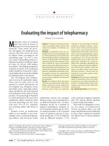
The basic strategy for achieving the airtightness target of 5 m3/(h.m2) @ 50 Pa outlined in deliverable 2 (Roberts et al. 2004) was still being adopted, with a thin parging layer applied to all external and separating walls to seal the blockwork, linked to air barriers formed by the plasterboard lining to the uppermost ceiling and the ground floor. The training package developed by the research team and the developers outlining specific site requirements for all site staff (summarised in Roberts et al. 2005) was still available and informal feedback was being given to the respective site management teams following each pressure test performed by the research team. Despite the availability of training materials and detailed feedback an upward trend in pressurisation results was apparent, as illustrated in figure 1. From February to June 2005 only 2 of the 13 dwellings tested gave results outside of the airtightness target, a 15% failure rate, but tests conducted between September 2005 and April 2006 the failure rate had risen to 61%, with 11 of the 18 dwellings having a mean air permeability greater the 5 m3/(h.m2) @ 50 Pa target.
2
SAP (DEFRA 2005) is an annual degree-day domestic energy model, which is consistent with European Standards BS EN 832 and BS EN ISO 13790. It is based on the Building Research Establishment Domestic Energy Model (BREDEM – Anderson et. al., 1996) and is the accredited modelling tool for demonstrating compliance with the Building Regulations-Part L for England and Wales (ODPM,2006).
3
Up to April 2006, despite considerable effort on the part of the developers and the research team, only 4 households had been recruited as against a planned 10. 4
th
Not including flats, by 7 April 2006 28 houses had been pressure tested at Stamford Brook by the Leeds Met research team with 3 2 an average mean air permeability of 5.02 m /(h.m ) @ 50 Pa.
1
Web version - July 2007
10 9 8 7 6 5 4 3 2 1
Ap r-0 6
6 -0 M ar
06 Ja n-
-0 5
O
N ov
ct -0
5
-0 5 Au g
05 Ju n-
M ay
5 -0 M ar
Ja n-
-0 5
0 05
3
2
Mean Air Permeability (m /(h.m ) @ 50Pa)
Stamford Brook – Deliverable 6: Detailed Airtightness Study
Test Date Apartment
2 storey detached
2 storey semi/end terrace
2 storey mid-terrace
2½ storey detached
2½ storey mid-terrace
3 storey semi/end terrace
3 storey mid-terrace
Figure 1. Variation of test results at Stamford Brook, February 2005 to April 2006. 6
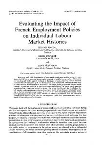
Of 31 properties tested between February 2005 and April 2006 a significant proportion (42%) exceeded the target of 5 m3/(h.m2)@50Pa. with a mean of 4.9 m3/(h.m2) @ 50 Pa. Figure 2 sets out the results by developer and by dwelling form. The best performing dwelling types were apartments and 2-storey houses with mean air permeability results averaging below 4 m3/(h.m2) @ 50 Pa. The highest mean air permeability results were measured on the 2½ storey dwellings (room-in-roof type design) where the best result recorded was 6 m3/(h.m2) @ 50 Pa. There was little difference between the means for the two developers with Redrow at 5.0 m3/(h.m2) @ 50 Pa and Bryant at 4.6 m3/(h.m2) @ 50 Pa, although it should be pointed out that a significantly higher proportion of Redrow plots tested were 2½ and 3 storey house types (52%) in comparison to that of the Bryant dwellings (17%).
2
Stamford Brook – Deliverable 6: Detailed Airtightness Study
Web version - July 2007
10 9
2
Mean Air Permeability (m /(h.m ))
8
3
7 6 5 4 3 2 1 0 A partment
2 sto rey detached
2 sto rey 2 sto rey 2½ sto rey 2½ sto rey semi/end mid-terrace detached mid-terrace terrace
3 sto rey semi/end terrace
3 sto rey mid-terrace
B ryant
Redro w
A ll
M inimum
1.75
2.91
2.04
2.98
5.97
6.09
4.64
4.41
2.04
1.75
1.75
M ean
3.99
3.92
3.87
3.40
6.09
7.61
5.28
5.33
4.60
5.01
4.93
M aximum
6.62
6.08
4.78
3.81
6.21
9.70
5.89
6.30
9.70
7.79
9.70
Figure 2. Stamford Brook air permeability results, by house type and developer, from February 2005 to April 2006 (error bars show standard deviation from the mean). 7
In deliverable 5 (Wingfield et al. 2006) the research team had suggested a number of potential reasons for the apparent deterioration in airtightness performance. These included: a) A shift in focus away from controlling airtightness due to other technical problems. b) Lack of quality control due to financial constraints and time pressures as developers approach their year end. c) Changes in site personnel and subcontractors. d) Reduced presence of Leeds Met researchers on site advising on airtightness issues. e) Reduced level of training on airtightness measures and control procedures. f) Material and product substitutions.
8
The revised project was designed to allow these concerns to be investigated further, identifying potential problems and where appropriate suggesting possible solutions. This study was one of the recommendations for improving airtightness suggested in deliverable 5, this and the other suggestions are listed below: a) A more precise investigation of the leakage paths would be possible if the dwellings had been observed during construction and a photographic record taken of the critical stages before being pressure tested. This was the approach adopted by a previous research project undertaken by the Leeds Met team (Johnston et al. 2006b) and it was suggested that a similar approach be taken on a limited number of dwellings at Stamford Brook. b) The developers should take a lead in developing design solutions for those 2½ and 3 storey dwelling types that were found to exceed the airtightness target. c) The developers should put in place an airtightness quality system for their design process for new dwelling types and also major design changes. The quality system should specify the
3
Stamford Brook – Deliverable 6: Detailed Airtightness Study
Web version - July 2007
location of the primary air barrier, identify any potential discontinuities in the air barrier and provide information on what measures need to be adopted on site to ensure its continuity during construction. d) It was suggested that the developers consider the appointment of a senior quality manager at either regional or national level. The remit of such a role would be to develop robust quality systems to monitor and control the performance of new dwellings not just in terms of airtightness but also other important measurable performance indicators such as continuity of insulation and acoustics. It is envisaged that the developers would want to develop their own testing expertise and to monitor a set of key performance indicators using a statistically based process control system. e) The developers’ site teams at Stamford Brook would find it useful to develop their own pressure testing programme to provide feedback on airtightness performance relative to the 5 m3/(h.m2) @ 50 Pa target.
4
Stamford Brook – Deliverable 6: Detailed Airtightness Study
Web version - July 2007
Methodology Plot selection 9 Following on from deliverable 5, which had already identified continuity of the primary air barrier in the 2½ storey dwellings as problematic, a number of additional dwellings were selected for further investigation. Two dwellings were selected from each developer for coheating tests, with particular attention being paid to the potential heat loss through the separating walls. Five further dwellings were selected specifically for the purposes of this detailed airtightness study, a pair of semidetached houses from Redrow and a terrace of three dwellings from Bryant. The four dwellings selected for the coheating tests were all comparatively simple box-shaped design with just a few more complicated details such as recessed front doors and bay windows. The five dwellings selected specifically for the detailed airtightness study were all 2½ storey dwellings containing a greater degree of design complexity. The final choice of dwellings was confirmed in July 2006. The locations of the selected dwellings for the airtightness study (Bryant plots B119, B120 and B121, and Redrow plots R116 and R117) are indicated on the site plan in Figure 3, the other plots highlighted (Bryant plots B116 and B117, and Redrow plots R110 and R111) are the final selections for the coheating tests.
Figure 3. Site plan with dwellings included in this study highlighted. 10
Table 1 provides additional details for each plot, containing the house type, developer, section and ground floor plan. This provides a comparison between the more basic cuboidal rectilinear geometries of the envelopes in the co-heating test houses and the increased complexity of the 2½ storey dwellings chosen specifically for the airtightness study. For the 5 houses selected for the airtightness study, maintaining the continuity of the air barrier involved contending with changes in plane and a range of different angles introduced by the room-in-roof structures. However, the comparison is far from straightforward as the level of complex detailing varied with all dwellings and a number of more challenging details (in terms of continuity of the air barrier) existed in both sets of dwellings.
5
Stamford Brook – Deliverable 6: Detailed Airtightness Study
Web version - July 2007
Table 1. Selected plots, with sections and ground floor plans. Plot
House Type B116
Chatsworth
Developer
Section
Bryant
B117
B119
XT2 (B119/B121) XT (B120)
B120
B121
6
Ground Floor Plan
Stamford Brook – Deliverable 6: Detailed Airtightness Study Plot
House Type R110
Mendip
Developer
Section
Web version - July 2007 Ground Floor Plan
Redrow
R111
R116
Avondale
R117
Design review 11 The research team and developers initially discussed potential plots in June 2006 when the developers were asked to review the detailed design approaches they intended to adopt and their methodology regarding construction sequencing and installation and maintenance of the air barrier. However, in the light of pressurisation test results obtained over the summer and autumn, neither developer felt it necessary to introduce any alterations with respect to these issues. Tests of Redrow properties 803 and 811, performed by the Leeds Met research team in September 2006 produced mean air permeability results of 2.27 and 3.21 m3/(h.m2) @ 50 Pa respectfully; similar tests on plots 806 and 807 in November 2006 gave results of 3.07 and 2.10 m3/(h.m2) @ 50 Pa. Pressurisation tests of Bryant plots 80 and 78 were performed in August and September 2006 by their own staff and provided results of 4.0 and 3.7 m3/(h.m2) @ 50 Pa. 12
The opinion of the research team was that the results achieved by Redrow on the 4 plots mentioned above appeared to be, in no small part, a direct consequence of the deployment of a high quality plastering team operating on a day rate basis. The insistence, by this gang, on a day rate enabled them to maintain their meticulous approach but resulted in a higher cost to the subcontractor which could not be passed on to the developer. This gang had previously worked on another site with a low air permeability target and were already familiar with some of the requirements and problems of achieving good airtightness using plasterboard on adhesive dabs. Observations by Leeds Met of this plastering team at work showed that they used more board adhesive than a typical plastering team in order to obtain better edge seals and employed techniques that were likely to limit air movement behind the plasterboard, for example by ensuring that the continuous ribbon of adhesive was positioned at the extreme edges of the board and also by more careful preparation prior to boarding. Eventually, the subcontractor took the decision to deploy this gang on an alternative site as he was not able to recover the additional costs from the
7
Stamford Brook – Deliverable 6: Detailed Airtightness Study
Web version - July 2007
developers. However, despite the loss of these higher skilled operatives the developer viewed the improvement in air permeability measured on these 4 plots as an indicator that no amendment of the design was necessary, and that the desired results could be achieved by concentrating their efforts on quality of workmanship through enhanced supervision. 13
The improved test results achieved by Bryant were partly due to the decision to return to constructing full top floor ceilings prior to installation of the internal partitioning. This was the technique used on the first dwellings constructed at Stamford Brook in February 2005, which gave mean air permeability measurements of 2.04 and 3.32 m3/(h.m2) @ 50 Pa. Returning to the original build sequence produced results of 4.0 and 3.7 m3/(h.m2) @ 50 Pa in two 2½ storey dwellings tested by Bryant staff during August/September 2006. Two further results below the target of 5 m3/(h.m2) @ 50 Pa five weeks later for an apartment and a 2 storey terraced dwelling gave the developer confidence that no further design/sequencing changes were required and to concentrate on quality of workmanship. Figure 4 illustrates the two different methods with Redrow continuing to adopt a partitioning first approach and Bryant installing ceilings first; nevertheless this is not the only sequencing issue exhibited here as in both cases there would have been benefits in applying the parging layer to the external and separating walls prior to erection of the metal studwork.
Figure 4. The potential for air leakage directly into the loft via top floor partition walls in Redrow plot R111 compared to Bryant plot B116 with a full ceiling installed before the partitioning. 14
In their different ways, both developers sought to achieve a continuous air barrier across the top of partitions and both would satisfy the advice provided the Accredited Construction Details (DCLG 2007 - ACD MCI-IW-08 Metal Partition Wall Head) as illustrated in Figure 5. However, as can be seen from Figure 4, the method implemented by Bryant appears to be the more robust method as there are no gaps to be sealed between the junction of the partition wall heads and ceiling plasterboard.
8
Stamford Brook – Deliverable 6: Detailed Airtightness Study
Web version - July 2007
Figure 5. Accredited Construction Detail MCI-IW-08 (DCLG 2007). Programme 15 The airtightness and coheating study dwellings were constructed between July 2006 and June 2007 with co-heating and pressurisation testing being undertaken between January and June 2007 as dwellings were completed. Figure 6 sets out the construction phases and testing programme for each dwelling. Plot
Jul-06
Aug-06
Sep-06
Oct-06
Nov-06
Dec-06
Jan-07
Feb-07
Mar-07
Apr-07
May-07
Key
B116
Foundations & Slab
B117
Structure
B119
Roof Construction
B120
1st & 2nd Fix
B121
Pressurisation Test
R110
Coheating Test
R111
Pressurisation Re-Test
R116 R117
Figure 6. Build programme for co-heating and pressurisation test dwellings. Observations, feedback and the research team’s role on site 16 Throughout dwelling construction the research team made regular visits to the site and observed construction, recorded their observations and discussed many of the issues arising directly with both the developers and the subcontractors. In accordance with the action research approach that has been adopted throughout the Stamford Brook project a two-way dialogue was maintained between site staff and the research team. This dialogue provided all parties with a greater understanding of the issues involved and with opportunities to put forward new ideas and techniques which may assist in solving many of the problems encountered.
9
Stamford Brook – Deliverable 6: Detailed Airtightness Study 17
Web version - July 2007
Since the final selection of plots for both coheating and airtightness studies was made in July 2006, in excess of 7,500 photographs were taken as a pictorial record of the build for the 9 plots chosen. These photographs have been indexed and are held in a searchable database allowing the research team to backtrack through the construction process to build up an illustrative sequence not only of the houses in general but also of specific details of interest. During the initial construction phases of both the coheating and airtightness test houses fortnightly site visits were sufficient to record the construction but at the more critical stages of construction, much more regular site visits were required to ensure that none of the significant details were missed. Whilst only 6 site visits in the 3 month period July to September 2006 were sufficient to maintain an adequate construction record, this increased to 18 visits over the following 3 months and 41 site visits between January and March 2007 whilst the coheating tests were running and pressurisation tests were performed on 6 of the 9 dwellings.
Pressurisation testing 18 Dwelling pressurisation tests were performed in accordance with ATTMA Technical Standard 1 (ATTMA 2006), using Energy Conservatory Minneapolis model 3 blower door systems equipped with DG700 gauges. For each test, air flow measurements were taken at a minimum of six pressures between around 15Pa and 60Pa over both pressurisation and depressurisation of the dwelling and a mean of the two values calculated. In all the pressurisation test results performed by the Leeds Met research team for the purposes of this report the values determined for air permeability are for the mean air permeability. The dimensions of the dwellings used for calculation of the building envelope areas were extracted from the developers’ AutoCAD drawings. 19
Additional temporary sealing beyond the measures outlined in ATTMA TS1 was necessary in a number of tests, some of these may have had slight positive affects on the pressurisation test results but it is unlikely that their effect would have been hugely significant. Where this temporary sealing was carried out details have been listed in the individual pressure test reports (Appendices 1 to 14). The additional sealing was necessary to provide results that would be representative of the fully completed dwellings, so details such as a missing loft hatch, trickle vent or window handle were all taped over and a window with a broken closing mechanism was taped shut.
Leakage detection techniques 20 Leakage detection was performed using smoke puffers under dwelling pressurisation as part of all pressurisation tests. Individual test reports from each of the tests are reproduced in Appendices 1 to 14 and contain photographic records as well as observational notes. Using leakage detection with smoke puffers enabled the research team to observed points of air leakage from inside the test dwelling, but was insufficient, in many cases, to identify actual air leakage paths from the habitable space to outside the dwelling. The relative severity of air leakage at the points identified could be determined to some extent by the velocity at which the smoke was drawn into the gaps, cracks and holes detected. By performing this type of leakage detection at similar pressure differentials, between 60 and 75 Pa above external pressure, an impression of the relative significance of each point of leakage was perceptible if not quantifiable in absolute terms. 21
When possible, leakage detection was also performed under dwelling depressurisation using infrared thermal imaging, using a FLIR Thermacam B4 IR camera. The limitations to thermographic leakage detection are listed in detail in BS EN 13187:1999 Thermal performance of buildings – Qualitative detection of thermal irregularities in building envelopes – Infrared method: Annex D. The biggest problem encountered using this method of analysis in the pressurisation testing at Stamford Brook was that unless the heating system had been fully operational for a number of days prior to the test, and the houses had been allowed to heat through, then a steady thermal state with sufficient temperature differential was unlikely to have been achieved. In plots R110 and R111 this was possible during the re-tests following the coheating tests, for the pressure test on plot R117 conditions were also suitable; some thermal imaging was also done on plot B121 but with a limited thermal differential definitive conclusions could not drawn from many of the observations. In the other dwellings no thermal imaging was possible since there was either insufficient temperature differential or continuing work prevented a steady state being achieved. Other factors such as direct sunlight and uninsulated primary pipework affected certain areas during the thermographic analysis, and prevented the use of thermal imaging in a number of rooms. Direct leakage paths were easily observed with this technique due to the large temperature differences but indirect paths were less obvious as the cooler air being drawn into the habitable spaces had often warmed up considerably by the time it emerged at the end of its path.
10
Stamford Brook – Deliverable 6: Detailed Airtightness Study 22
Web version - July 2007
The most powerful tool in determining leakage paths was a combination of both of the above techniques. Figures 7 and 8 illustrates the two methods being used in parallel; with the dwelling under pressurisation the movement of air can be observed into the roof space around both electrical and ventilation penetrations through the top floor ceiling of plot R111, under depressurisation cooler air can be observed entering the dwelling at the same points and also behind the plasterboard on an external wall at the loft boundary. Under different test conditions with an insufficient temperature differential between the roof space and habitable space, only leakage detection using smoke would have been possible and the “hidden” leakage path behind the dry lining at the loft perimeter would have remained undetected.
Figure 7. Detection of direct air leakage paths from the top floor bathroom of plot R111 into the attic, under dwelling pressurisation using smoke puffers.
Figure 8. Air leakage detection in R111 under dwelling depressurisation using infrared thermal imaging. 23
An example from plot R117 further illustrates how using both techniques for leakage detection can provide further insight as to the complexity of air movement within dwellings. Figure 9 shows the corner of a 1st floor bedroom at the wall/floor junctions of an internal and an external wall. Under dwelling pressurisation smoke can be seen entering gaps under the skirting boards on both walls indicating points of air leakage. However, under dwelling depressurisation thermal imaging shows warmer air emerging from gaps beneath the skirting board on the internal wall, yet on the external wall the air entering through a similar gap is cooler. This implies that there are two separate leakage paths being observed rather than the more straightforward direct air leakage paths observed in the figure 7. The warmer air emerging from the internal wall in this example has been heated up by central heating pipework running through the floor void in close proximity to the wall, an effect which was only possible to observe in this dwelling as it had been left relatively undisturbed for 2 days prior to the pressurisation test with the heating turned on. Without knowledge of the construction process and the routing of the pipework the image would have been difficult to interpret.
11
Stamford Brook – Deliverable 6: Detailed Airtightness Study
Web version - July 2007
Figure 9. Example of complex leakage paths observed in plot R117.
12
Stamford Brook – Deliverable 6: Detailed Airtightness Study
Web version - July 2007
Pressurisation Test Results Initial pressure test results 24 The results of the initial pressurisation test conducted on each dwelling included in this detailed airtightness study and the coheating study are contained in Table 2, the shaded rows denoting dwellings selected primarily for the coheating study. As can be seen from Table 2, 7 out of the 9 dwellings achieved a result below the target of 5 m3/(h.m2) @ 50 Pa in their initial test with permeabilities ranging from 2.67 to 5.45 and a mean of 3.84 m3/(h.m2) @ 50 Pa. In some cases dwellings were retested following either a degradation of sealing following the coheating test or following additional sealing works by the developers. The retest results are presented in table 3 below. Table 2 Initial test results for plots selected for the co-heating and detailed airtightness study Plot
Pressurisation 2
Permeability r coefficient of (m3/(h.m2) @ 50Pa) determination
25
Depressurisation 2
Permeability r coefficient of (m3/(h.m2) @ 50Pa) determination
Mean Air Permeability (m3/(h.m2) @ 50Pa)
-1 50
ach
(air changes per
Equivalent leakage area (m2 @ 10Pa)
hour @ 50Pa)
B116
2.84
0.975
2.67
0.992
2.75
3.04
0.022
B117
3.39
1.000
3.57
1.000
3.31
3.66
0.026
B119
2.87
0.994
2.90
0.998
2.89
2.50
0.034
B120
3.61
0.996
3.67
0.999
3.64
3.15
0.046
B121
4.16
0.999
4.17
0.999
4.17
3.61
0.048
R110
4.22
0.990
3.85
0.981
4.03
3.85
0.049
R111
2.99
0.980
2.68
1.000
2.84
2.46
0.034
R116
5.42
0.998
5.25
0.988
5.34
4.85
0.074
R117
5.81
0.998
5.45
0.999
5.63
5.10
0.069
In comparison to the previous test results achieved at Stamford Brook, the results obtained for this study compare favourably with those from the period October 2005 to April 2006 illustrated in figure 1. Figure 10 extends the timeline of that shown in figure 1 to include results listed in table 2 with all the previous initial pressurisation tests performed on properties at Stamford Brook by the research team and the 4 dwellings tested by the Bryant site team between August and October 2006.
13
Stamford Brook – Deliverable 6: Detailed Airtightness Study
Web version - July 2007
Mean Air Permeability (m /(h.m ) @ 50Pa)
10 9 8
2
Bryant self-tested plots with full ceilings
3
7 6
Plots included in table 2 above
5 4 3 2
Redrow plots with high quality plastering
1
Ju l-0 7
Ap r- 0 7
Fe b07
No v06
Se p06
Ju l-0 6
Ap r- 0 6
Fe b06
No v05
Se p05
Ju n05
Ap r- 0 5
Ja n05
0
Test Date Apartment 2 storey mid-terrace 2½ storey mid-terrace
2 storey detached 2½ storey detached 3 storey semi/end terrace
2 storey semi/end terrace 2½ storey semi/end terrace 3 storey mid-terrace
Figure 10. Stamford Brook initial pressurisation test results, February 2005 to May 2007. Re-test results 26 Some of the dwellings listed in Table 3 were also re-tested, either after the coheating test had been carried out (plots B116, R110 and R111), or after additional sealing had been undertaken (plots R116 and B121). The results for these pressurisation tests are listed in table 3, again the coheating test dwellings are shaded. Table 3. Pressurisation re-test results Plot
Pressurisation 2
Permeability r coefficient of determination
(m3/(h.m2) @ 50Pa)
Depressurisation 2
Permeability r coefficient of determination
(m3/(h.m2) @ 50Pa)
Mean Air Permeability (m3/(h.m2) @ 50Pa)
-1 50
ach
(air changes per
Equivalent leakage area (m2 @ 10Pa)
hour @ 50Pa)
B116
3.55
0.998
3.59
0.999
3.57
3.95
0.030
R110
5.00
0.998
4.55
1.000
4.78
4.09
0.055
R111
3.37
0.998
3.03
0.998
3.20
2.77
0.038
R116
4.58
0.998
4.32
0.997
4.45
4.04
0.056
B121
3.34
0.997
3.19
0.997
3.27
2.83
0.037
27
In plots B116, R110 and R111 a decrease in the airtightness of each of the dwellings was recorded in pressurisation tests performed after the co-heating tests had been carried out. In plots R116 and B121 the initial tests were performed with the primary air barrier complete but the dwellings not fully finished, the increase in airtightness measured in the re-tests of these two dwellings was due to some additional internal sealing; in plot R116 to a point where the mean air permeability had become 4.45 m3/(h.m2) @ 50 Pa, a result that was now inside the target figure for the development of 5 m3/(h.m2) @ 50 Pa.
28
A detailed analysis of the results contained in table 3 is included in paragraphs 113 to 117 under the heading Secondary Sealing.
14
Stamford Brook – Deliverable 6: Detailed Airtightness Study
Web version - July 2007
Leakage Detection 29
Identification of points of air leakage and detection of possible leakage paths was performed as part of the each of the pressurisation tests. Many of the detected air leakage points and paths were common to a number of different dwellings and to both developers. This section has been divided into 2 sub-sections as follows: a) Direct leakage paths – These are defined as the movement of air directly through the primary air barrier either into or out of the insulated envelope. In the case of Stamford Brook the primary air barrier is formed by the solid ground floor, the plasterboard to the top floor ceiling and the parging layer applied to the blockwork on all the external and separating walls. The 2½ storey dwellings (plots B119, B120, B121, R116, R117) introduced additional complexity as the air barrier has to be capable of negotiating the geometry of sloping ceilings, dormer windows, and associated roof voids involving changes in material (such as from masonry to plasterboard or timber boards) and plane. b) Indirect leakage paths – These are defined as air movement through interconnected voids on the inside of the air barrier before flowing through discontinuities to the outside. Such air movement often involves complex routes that change depending on wind and other external conditions. In many cases what is actually detected by a smoke puffer is air movement that is the result of leakage through the envelope at a point some distance away from where it is detected.
Direct leakage paths 30 The following direct leakage paths were common to a number of dwellings covered as part of this study and are illustrated with examples of smoke testing and IR leakage detection. 31
Leakage detection at front door thresholds was not possible due to the placement of the blower door for the duration of all the pressurisation tests apart from the re-test of plot B121 (Appendix 14). For all the other tests too much turbulent air movement was present around the front door thresholds for detection using either smoke puffers or IR imaging. Hence leakage detection at thresholds was primarily performed at the rear doors. Out of the nine plots included in this study, five had traditional single-leaf rear doors and six had double-leaf patio doors. Air leakage occurred around the thresholds in all of them to varying degrees of severity. Detection of air movement under the threshold was a routine occurrence usually through gaps in the sealant, often caused by misapplication, adhesive failure due to inadequate surface preparation or an incorrect choice of sealant (figure 11). In the majority of cases infiltration was also observed around the skirting board at the reveals. Even where sealant had been successfully applied to the skirting/floor junction, as in plot B120, air movement was still detectable between skirting and back door frame.
1
3
2
Figure 11. Air leakage at the patio door threshold in plot R110 (1 & 2) and at the threshold reveals of single leaf back door in plot B120 (3) 32
The gallery windows in plots R116 and R117 also displayed air leakage at the junctions with the ground floor, much the same as was observed at the thresholds with the window frame sited directly on top of the floor slab. The thermal image in figure 12 shows distinctly cooler air entering the dwelling at this junction under dwelling depressurisation, indicating a direct leakage path.
15
Stamford Brook – Deliverable 6: Detailed Airtightness Study
Web version - July 2007
Figure 12. Air leakage at the gallery window “thresholds” in plots R116 and R117, the thermal image showing infiltration in plot R117 at this detail 33
Air leakage was observed around the ground floor patio doors in all plots where this detail existed, to varying extents of severity (figure 13). As was observed with both the thresholds and the gallery windows, the most common points of leakage were at the junctions of the skirting boards with both the frame and floor, and also under the sills where the sealant had been often been inadequately applied or had subsequently failed.
Figure 13. Direct air leakage at patio doors thresholds in various plots. 34
Similarly significant air leakage was observed where patio doors had been installed on the 1st and 2nd floors (figure 14). Leakage was detected to similar degrees of severity regardless of whether the patio doors were installed where the joists ran parallel or perpendicular to the external wall.
2
1
3
5
4
Figure 14. Infiltration at patio doors installed on intermediate floors in plot R110 with joists running parallel to the external wall (1, 2 & 3) and plot R111 with joists running perpendicular to the external wall (4 & 5).
16
Stamford Brook – Deliverable 6: Detailed Airtightness Study 35
Web version - July 2007
Significant air leakage was also observed at the floor junctions directly in front of these intermediate floor patio doors in both plots R110 and R111, although this was noticeably reduced in plot B120 where additional attempts had been made to seal the junction between the flooring panels (figure 15). Further discussion of this detail is contained in paragraphs 83 to 85 below.
Figure 15. Smoke detection and IR images of air movement through gaps between flooring panels directly in front of the intermediate floor balconies in plots R110, and the additional sealing applied in plot B120. 36
Direct leakage paths were observed at the bay windows in all the plots where these were present (plots B116, B117 and R111). A number of these paths are expected to be sealed to some degree (depending upon the quality of the sealant application) at the internal surface by the subsequent application of the decorators’ caulking during snagging, however there were also leakage paths through gaps between individual elements of the bay windows, and at the sills, which may still remain upon dwelling completion (Figure 16).
Figure 16. Air leakage through gaps at bay windows in plots B116 and R111 37
Additional leakage paths were detected around other windows, through some small holes around the edges of the frames but mainly at or around the window sills. Figure 17 illustrates typical leakage points around window sills which may get sealed internally upon decoration/snagging but
17
Stamford Brook – Deliverable 6: Detailed Airtightness Study
Web version - July 2007
some small gaps invariably remain. Thermal imaging also illustrates that although this gap may get sealed on the surface, it is likely that there will still be a remaining leakage path under the sill board into the plenum behind the plasterboard where air can move from this void directly to outside or into the cavity.
Air leakage through visible gaps beneath window sills
At visible gaps around a sill board
Air movement into the void behind the dry lining where no visible surface gap exists
Linking of infiltration at the window sill to other leakage paths at the bay in plot R111
Figure 17. Air leakage at window sills. 38
Where penetrations were made through the walls after the dwelling had already been dry-lined there appeared to be problems sealing around them. This was common around waste pipes and boiler flues where suitably sized holes are core-drilled through the plasterboard and external walls then only sealed externally for weatherproofing and internally for aesthetics, not at the less accessible parged blockwork layer which provides the air barrier. The result is that air can move easily between the cavity and the void behind the plasterboard. This is compounded when the penetration also passes through the backs of kitchen units making sealing at the blockwork virtually impossible, thus requiring a different approach either to sealing products or to the build sequence. Figure 18 illustrates direct air leakage at these penetrations; for a washing machine and kitchen sink waste pipe in plot R117 where air movement is through visible gaps, and around a boxed-in boiler flue in plot R110 where the penetration is hidden from view and the thermal image reveals the extent to which the cooler external air is drawn into the void behind the plasterboard due to the lack of effective sealing at the blockwork layer.
18
Stamford Brook – Deliverable 6: Detailed Airtightness Study
Web version - July 2007
Figure 18. Infiltration in plot R117 around the waste pipes for the washing machine and kitchen sink, and around the boiler in plot R110. 39
Direct air leakage through and around the loft hatch was detected in each of the 9 properties included in this study (figure 19). This was observed around the loft hatch surround where the junction with the ceiling was either unsealed or shrinkage cracks had developed, through the open hole for the loft hatch key in 2½ and 3 storey dwellings, and between the door and the hatch where the compressible seals were often not continuous and rarely compressed along all 4 edges.
Around the loft hatch surround in plot B120
Through the keyhole in plot B121
Between the trap and door in plot R111
The photograph of the loft hatch in plot R110 indicates some air leakage, the IR image of the same detail provides further illustration of the extent of the problem.
Figure 19. Direct air movement at the loft hatch between the roof space and living space. 40
In all the properties tested there was some air leakage directly around electrical penetrations into the loft. This occurred around the wiring for ceiling mounted lights, light switches and smoke alarms. Figure 20 shows the light fittings fitted in en-suites and bathrooms which invariably allowed some air leakage, and leakage through the central rose fixings where the penetration for the wiring had not been sealed or the sealant had been displaced by manipulation of the wiring. As the
19
Stamford Brook – Deliverable 6: Detailed Airtightness Study
Web version - July 2007
covers for central light fittings are not specifically designed to be airtight, air movement remains through and around the fitting after they have been screwed on.
Figure 20. Air leakage into the loft around the 2nd floor bathroom lights in plots R110 and B119, and at standard ceiling-mounted fixings for lights in top floor bedrooms in plots B121 and B119. 41
Ventilation penetrations into the loft were a common source of direct air leakage for both developers. Sealing around the ductwork for the MEV systems was the duty of the system installers which appeared not to have been performed thoroughly enough particularly where the penetrations were less accessible in the gap between the ducting and wall. The extract vents were generally not sealed to the ceiling leaving air movement possible at their interface with the ceiling which could be observed even when the vents themselves had been temporarily sealed (figure 21).
Figure 21. Ventilation ducts in B119 and vent in R110 42
Air movement directly between the living space and outside was detected at all rooflights to varying degrees, both around the frames and between the rooflights and frames (figure 22). Although two different manufacturers of rooflights were used by the two developers, the same leakage paths were detected for both, neither one performing better or worse than the other. Infiltration through the rooflights occurred irrespective of the location, whether fitted in the room in roof locations in the 2½ storey dwellings or those fitted in the ground floor kitchen/dining rooms in plots R116 and R117.
20
Stamford Brook – Deliverable 6: Detailed Airtightness Study
Web version - July 2007
Figure 22. Air leakage at the rooflights, around the frames in plots R116 and R117 and between the rooflights and frames in plots B120 and B121. Hidden leakage paths 43 Much of the leakage detection performed during the pressurisation tests revealed indirect leakage paths rather than direct leakage. The examples given below show leakage detection with either smoke testing or IR thermal imaging where what is identified is a point of air leakage into one of the many interlinked voids within each dwelling. With nothing in place to limit the movement of air between the construction voids, air leakage detected at many of these points may be entering or leaving the habitable space at some other point far removed from the position where it was originally detected. The individual pressure test reports contained in the appendices provide many examples of indirect air leakage, the prevalence of which can easily encourage the misconception that these are of greater consequence than they actually are; they highlight instances of air movement into the intricate system of connected cavities inside the conditioned envelope and not direct paths to the outside. 44
The detection of air movement at the ground floor perimeter and service penetrations was commonplace. Where the path of the smoke could be seen it usually travelled upwards into the void behind the plasterboard or horizontally along the void behind the back of the skirting board. Figures 23 to 25 show examples of points of air leakage on the ground floor leading into the network of interconnected voids, many more examples can be found in the individual pressure test reports included in the appendices. In the Bryant dwellings there were instances where the screed had not filled the gaps between the soil pipes and walls, some smoke was observed to move downwards towards the insulation layer beneath the screed and may have escaped via a leakage path between wall and screed into the wall cavity. However, this could not be verified from smoke detection.
Figure 23. Air leakage around ground floor service penetrations.
21
Stamford Brook – Deliverable 6: Detailed Airtightness Study
Web version - July 2007
Air movement was observed at the ground floor perimeter, with air leakage most commonly detected at room corners with unfinished or inadequately sealed junctions and also around the bottoms of internal door frames. Even in plots B119 and B120 where mastic sealant had been applied around all ground floor room perimeters air leakage was detected. The perceived severity of air leakage at points along these junctions was low in comparison with many areas of leakage.
Figure 24. Air leakage at the ground floor/wall junctions.
Ground floor kitchens, utility rooms and WCs exhibited air leakage at the ground floor/wall junctions significantly worse in areas that were left unfinished, presumably because they were out of direct view. This mainly occurred underneath kitchen units and at spaces left for kitchen appliances, but was also frequently observed at boxed-in services or those hidden by sanitary ware. In dwellings where similar penetrations had been boxed-in or covered over it was normal to see air leakage around the boxing or around the plinths under kitchen units
Figure 25. Air leakage under kitchen/utility room units. 45
Air leakage was detected at a number of junctions connected with the intermediate floors and stairs. The staircases provide ample opportunity to link together many other voids (intermediate floor voids, dry-lining voids, partition walls voids, and service voids for WC’s (R110 &R111) and cylinder cupboards (B116 & B117) allowing relatively unrestricted movement of air between these voids and contributing to the aforementioned complex leakage paths. Figures 26 to 28 illustrate just some of the many points of leakage into the stair and intermediate floor voids detected. The exchange of air between the habitable space and the complex of interconnected voids occurred through a number of points around the stairs, such as around newel posts, junctions with intermediate floors, around the edges of risers (particularly where the stairs turned a corner) and through shrinkage and settlement cracks at the top of the wall stringers.
Figure 26. Air leakage around staircases.
Air movement into intermediate floor voids through joints between flooring panels regularly occurred in circumstances where flooring panels had to be cut or altered. This was common at doorways over load bearing internal walls, where repairs had to be made to the floor due to damaged boards and where holes had been cut for access to services inside the floor voids.
Figure 27. Air leakage directly into intermediate floor voids.
22
Stamford Brook – Deliverable 6: Detailed Airtightness Study
Web version - July 2007
Air leakage at the intermediate floor/wall junctions was consistently at its most severe on the top floor of the dwellings included in the study, whether 2, 2½ or 3 storey dwellings. Air leakage at wall/floor junctions in 1st floor rooms in the 2½ and 3 storey houses appeared to be less dramatic than at similar junctions on the top floor but noticeably greater than on the ground floor. Air leakage at room perimeters was commonplace, particularly where sealant was missing, had failed or had been misapplied, and was markedly worse in less visible areas such as inside the built-in wardrobes and cylinder cupboards. It was not always cooler air that emerged from these gaps during dwelling depressurisation, often the air movement detected was isothermal or even warmer than that in the habitable space due to the location of internal pipework; thus demonstrating the degree of complexity associated with some of these hidden air leakage paths.
Figure 28. Air leakage at intermediate floor perimeters. 46
Aside from direct leakage into the loft via ceiling-mounted light fixings, air leakage through the electrical service penetrations was indirect air leakage into wall voids, intermediate floor voids and service risers. As with the floor/wall junctions, air leakage on the top floors generally appeared more severe than similar switches, sockets and light fixings on other floors, but there were particular concerns regarding air leakage around electrical consumer units and kitchen/utility room electrical penetrations. Most of the air movement around plumbing and ventilation penetrations was also indirect, into intermediate floor voids and service voids and air leakage around radiator pipework into the wall voids. The application of sealants around plumbing penetrations recurrently suffered from accessibility problems and in hidden areas such as behind bath panels, kitchen units and boxing, sealing was rarely to the same standard observed in more visible areas. Figures 29 to 31 show examples of detected indirect air leakage around various electrical and plumbing penetrations. Detected air leakage at electrical penetrations displayed a great variation between dwellings, appearing to increase in significance in those properties with a greater overall mean air permeability. However, within individual dwellings it generally followed a comparable pattern to that at wall/floor junctions, with detected air leakage at similar fittings appearing most frequently and with greatest severity on the top floor and of lesser significance on the ground floor regardless of whether on external or internal walls.
Figure 29. Air leakage detected around the electrical penetrations.
23
Stamford Brook – Deliverable 6: Detailed Airtightness Study
Web version - July 2007
Accessibility problems arose from sequencing issues and the placement of plumbing penetrations close to wall/floor and wall/wall junctions, and from penetrations placed closely together. In bathrooms Redrow favoured services entering the intermediate floor void and joining up with the service riser, Bryant favoured a service void along an external or party wall into which all penetrations would enter and get sealed when tiled. Service penetrations into the intermediate floor were usually sealed around well where they were visible, but not to the same standard where vision and access was restricted. The sealing of penetrations into the tiled service voids often relied on the grouting to provide an airtight seal rather than a more suitable flexible sealant. Gaps around the perimeters of bath panels and shower fascia panels habitually provided air leakage paths from the living space into the void beneath the bath or shower. Similar problems were observed in other wet rooms with smoke detection around kitchen units and pipework boxing often leading to inadequately sealed service penetrations obscured by them. Figure 30. Detected air leakage at plumbing penetrations.
Air movement into the pattress boxes for positioning of radiator pipework was commonplace, and usually most severe on internal partition walls on upper floors. The placement of covers over the pattresses had little significance on air movement at this detail as they were not observed to be sealed around effectively. Although this is listed as an indirect leakage path, in the Avondale house types the radiators in the 2nd floor rear bedrooms were fixed to the knee wall behind which was a roof void, air leakage detected here was directly into the roof voids. Figure 31. Air leakage detected around radiator pipework. 47
Using infrared thermal imaging under dwelling depressurisation, indirect air movement was detected between the void behind the plasterboard dry-lining on the top floor and the ventilated loft space all around the dwelling perimeter at the loft boundary. This was possible to detect when plots R110 and R110 were re-tested immediately following the co-heating tests, with residual elevated internal temperatures around 10°C higher than the external temperature. Air movement between the void behind the plasterboard and the loft at these junctions should have been restricted by solid continuous ribbons, but it was obvious from the images in figure 32 that these have not been fully achieved. At the eaves junctions in both plots it was possible to see cooler air from the loft being drawn through the “continuous” ribbons of plasterboard adhesive and around the windows. On the separating and gable walls the air being drawn into the plenum behind plasterboard had a greater cooling effect, either due to a greater airflow or because the air entering from the loft at this junction was cooler than at the eaves; this could be possible as the roof trusses ran parallel to the separating wall and the small gap (25~50mm wide) between the end truss and the wall was insulation deficient as the low density recycled cellulose insulation appeared to settle over the top of this gap and not drop into it.
24
Stamford Brook – Deliverable 6: Detailed Airtightness Study
Web version - July 2007
Figure 32. In plot R110 cooler air being drawn in behind the dry-lining along the eaves junction and the adjacent separating wall. In plot 111 the cooler air can be seen being drawn down around 2 windows at the gable walls and along the loft boundary at the party wall. 48
A similar phenomenon was observed at top floor internal partition walls (figure 33), where air movement from the attic into the partition wall voids can be seen. The highly conductive metal studwork can be observed within the partitioning providing a more regular pattern than the swirls of air around the dabs seen on external and party walls. Darker coloured cold spots can be seen along the top member at regular intervals coinciding with holes in the Gypframe channelling and at junctions with the vertical members.
Figure 33. Infiltration at the tops of partition walls in plot 111 on either side of the 2nd floor bathroom, the pattern of the studwork is visible and contrasts with the airflow around the plasterboard dabs on an adjacent external wall. 49
Thermal imaging of the 2nd floor service voids in plot R110 revealed air leakage into these voids from the loft (figure 34). Not only was cooler air detected being drawn in from the roof space, but it can also be observed distributing from the service voids into the plenum behind the plasterboard dry-lining along the party wall in both the rear bedroom [A] and the bathroom [B], and emerging into the habitable area in the front bedroom [C] at the wall/floor junctions where the thermal images show not only the point of air leakage at the base of the skirting but the full air leakage path from the habitable area into the ventilated loft space.
25
Stamford Brook – Deliverable 6: Detailed Airtightness Study
[A]
[B]
Web version - July 2007
[C]
Figure 34. 2nd floor service voids in plot R110 with thermal images taken during dwelling depressurisation showing infiltration from the roof space.
26
Stamford Brook – Deliverable 6: Detailed Airtightness Study
Web version - July 2007
Construction Process Detail Observations 50
Site observations made during the build process raised a number of construction issues regarding the continuity of the primary air barrier; these were predominantly, but not exclusively, issues relating to design and the planning of construction sequence. Keeping a searchable database of photographs taken of details of concern in each plot throughout the build allowed a retrospective analysis of many of these details, particularly those concerning the sequence of construction. Many of the concerns raised by the research team during the earlier stages of the build were addressed by subsequent work, but others still remained upon the dwelling completion or at least at the time the pressurisation test was performed. Many additional observations were made regarding secondary sealing which would affect the routes taken by air movement within the interconnected voids within the dwelling but did not affect air movement through the primary air barrier and as such have not been included in this section. Issues concerning the efficacy of secondary sealing are discussed in paragraphs 113 to 117 under the heading Secondary Sealing.
Ground floor service penetrations 51 In addition to the air leakage observed during the pressurisation tests there were other concerns surrounding certain ground floor service penetrations which it was not possible to observe when the dwellings were tested, these were possible sources of direct air leakage obscured by kitchen/utility room cupboards and plinths and by the boxing-in of pipework. 52
Figure 35 shows the mains water supply into the kitchen of R116 which enters via a duct provided by a section of drainage pipe, it is presumed unlikely that the gap around the supply pipe will be sealed on completion of the dwelling leaving a significant leakage path. Mineral wool had been loosely packed around this supply pipe in 2 of the 9 dwellings observed for this study, which may increase the turbulence of the airflow through this detail but will not prevent it. There is also the potential for air movement into the void behind the dry lining as the wall/floor junction behind the units will also remain unfinished. One solution to improving the airtightness of this entry would be to adopt the approach used for a waste/soil connection as illustrated in figure 36. This would involve the seal being fitted over the supply pipe prior to the installation of the kitchen units, and may necessitate a small change in the build sequence. Indeed, it is a detail already used for some waste connections at Stamford Brook as indicated in figure 37.
Figure 35. Mains water supply pipe in the kitchen of plot R116.
Figure 36. Waste pipe adaptor which could possibly be used to reduce air leakage around the water supply pipe (source: www.hepworthdrainage.co.uk/literature_downloads/Technical_Manual/Applications.pdf).
27
Stamford Brook – Deliverable 6: Detailed Airtightness Study
Web version - July 2007
Figure 37. Utility room water supply and waste pipes in plot B119 53
The build sequence can also raise problems where ground floor service penetrations are concerned. In figure 38 the gap in the floor around the service void containing the soil pipe has been boxed in and the kitchen units installed before the floor has been finished, linking the void behind the cooker to the service riser and potentially the void behind the plasterboard in the kitchen. Even if the fraction of the hole visible in figure 38 is sealed before the cooker is mounted, the inaccessible sections are likely to remain unsealed and will still permit air movement.
Figure 38. The gap in the screed at the base of the service void in plot B120 left which should have been filled prior to installation of the kitchen units. Thresholds 54 Air leakage at the thresholds has been observed in all the properties tested, to varying degrees of severity, and occurs at all types of doors and patio doors regardless of door manufacturer, developer or floor construction. Typically air movement was observed under the threshold itself where the sealant had been misapplied or had failed and around the skirting boards at the reveals, both at the junctions with the floor and the doorframe. 55
The construction sequence for the back-door thresholds in the Bryant plots B119, B120 and B121 is illustrated in sequence in figure 39. The external brickwork at the threshold was cut away to be replaced by a threshold slab and the insulation and screed were then laid on top of the floor slab. Any unfilled holes at the sides of the threshold were covered by the perimeter insulation which was subsequently chipped away so as not to interfere with the placement of the door frame and the plasterboard dry-lining, but leaving gaps at the sides of the threshold where air movement may be possible into the cavity. These remaining gaps were then covered over by the skirting board allowing direct transfer of air from behind the skirting boards directly into the cavity. Even when the skirting boards were sealed at the floor junction air leakage remained at the junction of the skirting and the door frames. The pressurisation re-test of plot B121 (appendix 14) was performed with the blower door sited in the back door, instead of the usual placement in the front door, and air leakage was duly detected at similar junctions around the front door.
28
Stamford Brook – Deliverable 6: Detailed Airtightness Study
Web version - July 2007
1
2
3
4
5
6
Figure 39. The build sequence of the threshold for Bryant, leaving the potential for air transfer between the cavity and the void behind the skirting. 56
The dwellings constructed by Redrow used a different floor construction, with insulation beneath the slab, leaving an open section of the cavity between the slab and outer leaf brickwork which required retro-filling. The build sequence was not the same in the 4 dwellings included in this study, with this gap being filled at different stages of construction, the 3 examples illustrated (figures 40, 41 and 42) all exhibit different build sequences and all still maintain the potential for air leakage at the sides of the threshold into the cavity.
57
In plot R117 the cavity at the front door threshold was not filled until very late in the construction process, after the skirting boards had been fitted (figure 40), leaving a distance of around 50mm between the front of the skirting board and the jamb blockwork where the cavity may not get filled and air allowed to move freely between the cavity and the voids behind the dry-lining and skirting.
1
2
3
Figure 40. The front door threshold in plot R117. 58
In plot R111 the cavity at the front door threshold was filled at a very early stage of the construction process, before the door and frame had been fitted (figure 41). This sequence reduces the size of the opening into the cavity behind the skirting and dry-lining but does not eliminate the leakage path completely as the parging layer and dry-lining do not seal the gap left at the bottom of the cavity closer. Resultant gaps underneath the threshold and at the skirting board junctions with the floor and frame are difficult to render airtight and air leakage is presumed to remain at this detail upon dwelling completion, although due to placement of the blower door in the front doorway for the pressurisation tests it was not possible to confirm this during the leakage detection performed as part of the tests.
29
Stamford Brook – Deliverable 6: Detailed Airtightness Study
1
2
Web version - July 2007
3
Figure 41. The front door threshold in plot R111. 59
Figure 42 displays the patio door threshold in plot R116 where the cavity was filled after the door and frame had been installed, but prior to dry-lining and the 2nd fix joinery being installed. As in figures 40 and 41 gaps still remained behind the skirting and plaster board with air movement directly into the cavity a consequence.
Figure 42. The patio door threshold in plot R116. Recessed front door 60 All 4 of the Redrow plots examined had front doors which were recessed to give an arched porch. This detail was picked up in the design review as both a potential thermal bridging and airtightness issue. Initial concerns that the jambs and recessed head would not get fully insulated were substantiated by the research team who examined additional plots on the site containing the same details and observed a lack of insulation injection holes, this was reported back to the site management and the problem rectified. However, the airtightness issues appeared to remain unresolved. 61
Figure 43 shows the front door detail during construction, illustrating the difficulties of maintaining air barrier continuity in the face of complex geometry and changes of plane. The cavity masonry is returned to form a door recess that extends below the first floor structure and effectively links the cavity in the external wall with the intermediate floor void. A cavity wall above the door itself also creates a link into the floor void. The various air paths are illustrated in figures 43 and 44.
30
Stamford Brook – Deliverable 6: Detailed Airtightness Study
Web version - July 2007
Figure 43. The recessed front doors in plots R116 and R111.
Figure 44. Typical as built plan and section of the recessed front door. 62
With many services running through the intermediate floor void above this detail, any infiltration above the door can result in complex pathways moving through such voids as this. The movement of air above the recessed front door into the floor void can also be seen using infrared thermal imaging with stratification of the temperature in the floor voids in the zones between the joists running parallel to the external wall (figure 45).
Figure 45. Stratification of temperature in the intermediate floor void directly above the recessed door detail (plot R110 - no induced pressure differential). Parging layer 63 The primary air barrier on the walls at Stamford Brook is a 3~6mm parging layer applied to the inner leaf blockwork on all the external walls and an 8mm cement render mix applied (in leiu of the
31
Stamford Brook – Deliverable 6: Detailed Airtightness Study
Web version - July 2007
parging layer) to separating walls applied by the plastering subcontractor. The purpose of the parging layer being not only to seal the blockwork but also provide conceptual clarity of where and what the air barrier is. On the ground floor in each dwelling the parging layer was applied prior to the stairs being installed; however, on the upper floors as was shown in figure 4, it was not unusual for variations in the build sequence resulting in application of the parge coat occurring after the erection of the internal studwork (Figure 46).
Figure 46. Erection of partitions before parging; creating an air barrier discontinuity (plot B116). 64
It was not only partitioning that made the application of a continuous parging layer difficult to achieve, where plumbing installations had been positioned before the parge coat had been applied discontinuities often occurred. Figure 47 shows radiator pipework in a bedroom and water and soil pipes in a bathroom on the 1st floor of plot B117 fixed prior to parging, and in the 2nd floor of plot R110 the area of unparged wall that can be left as a result of such an obstacle. If the build sequence had involved parging prior to any 1st fix plumbing work these potential problems would have been eliminated.
Figure 47. 1st fix plumbing installations in plots B117 and R110. 65
In the nine plots included in this study there was only one example of a staircase being installed before the wall had been parged (figure 48). The gap between the stringer and the party wall has been partially sealed with expanding foam but not sealed completely, leaving the potential for air movement through the unsealed blockwork and linking the intermediate floor voids with partition wall voids and the void behind the plasterboard on the party wall. The linking of such voids provides for air movement throughout the dwelling and assists in the creation of the complex “hidden” leakage paths already discussed.
32
Stamford Brook – Deliverable 6: Detailed Airtightness Study
Web version - July 2007
Figure 48. The staircase between the 1st and 2nd floors in plot R110, installed before the parge coat had been applied to the party wall. 66
The other main discontinuity in the parging layer occurred at the interface between the walls and the intermediate floors. In all cases joists, edge struts and floor decking were fitted before parging was carried out, resulting in inaccessible areas of wall, particularly when joists ran parallel with the walls. Figure 49 shows a number of examples. This problem could be resolved by modifying the build sequence and access arrangements to enable parging behind joists before they were positioned.
Figure 49. Examples from all of the Bryant plots studied, illustrating where gaps in the parging layer behind joists, joist struts and floor decking appear. Continuous ribbons of plasterboard adhesive 67 In common with standard construction practice, the specification at Stamford Brook calls for continuous ribbons of adhesive around the plasterboard dry lining on all external and separating walls. Figure 50 demonstrates the application of the ribbons of plasterboard adhesive as a continuous string of dabs, the plasterboard was pushed on to these ribbons to the desired depth, raised vertically by about 25~30mm with a board lifter and then 2 off-cuts of plasterboard placed underneath for support until the adhesive dried. This technique leaves a channel for air movement around the perimeter of the wall between the ribbons of adhesive and the perimeter junctions with adjacent walls, the ceiling and the floor as well as leaving gaps in the ribbons themselves.
33
Stamford Brook – Deliverable 6: Detailed Airtightness Study
Web version - July 2007
Figure 50. Continuous ribbons of plasterboard adhesive on an external wall in plot R116. 68
Where the dry lining conceals certain plumbing penetrations causing the depth of the ribbons to be excessive different techniques were adopted by different plastering teams. One technique was to cut out sections of the plasterboard around protruding pipework and fill the gaps around the pipes with plasterboard adhesive sealing; another was to “double board” these areas, first fixing pieces of board to the wall around the projecting pipework to enable a second board to be fixed using dabs and ribbons of adhesive as normal. The second technique appeared to complicate matters, and required that continuous ribbons be achieved at both the plasterboard/wall interface and the one between the two sheets of plasterboard thereby doubling the chances of failure.
69
Around openings it was often possible to view a ready-made cross-section of the continuous ribbons of plasterboard adhesive. Figure 51 shows three examples from the same room, the kitchen/breakfast room in plot R116, where continuous ribbons on the external walls (applied as in figure 50) were visible at a number of different door jambs. It can be seen that although the ribbons of adhesive are continuous in that they run along the full length from floor to ceiling, they do not form a complete seal and will allow air to move through them. The three examples depict a best case, where only a few very small gaps exist (possible where air escapes as the board is pushed on to the wall), a typical example where larger gaps remain between every 2 or 3 dabs, and the worst observed where gaps were visible between each dab of plasterboard adhesive. The examples are situated on external corners and still have the potential for the gaps in the adhesive to get filled when the reveal boards are fitted, but this is not the case on internal corners and gaps such as these will almost certainly exist in most areas leaving plenty of room for significant air movement behind the boards.
Figure 51. Photographs of plot R116, at the front door, back door and patio door; the gaps in the plasterboard adhesive ribbons are illustrative of the good, typical and poor examples observed.
34
Stamford Brook – Deliverable 6: Detailed Airtightness Study
Web version - July 2007
Built-in joists 70 Both developers used built-in timber I-beams to form intermediate floors, a construction that is particularly difficult to make airtight. Most of the problems observed relate to the difficulties created by access to the junction between the block work and each I-beam and the fact that the materials involved have quite different movement characteristics. 71
Problems with access during block laying to both wall faces of the blockwork, both at party walls and external walls were observed. This meant that it would have been difficult for the bricklayers to ensure that full perpends and bedding layers were achieved and that excess mortar was properly struck off. Typically, the joists and floor decking were built up and used as a working platform, and the blockwork subsequently laid between the joists up to the floor level. This work sequence resulted in particular problems at the party walls where the bricklayer had to reach down from the floor to lay blocks either between or closely parallel to the joists. Also, when the blockwork had been built up on one side of the party wall, access to the second side was restricted further. Figure 52 illustrates where many of these difficulties arise and clearly shows the lack of working space available for laying blocks down into the party wall cavity at the intermediate floor voids from the top of the floor.
Figure 52. Difficulties of gaining access to construct well sealed blockwork in intermediate floor space. 72
The same problems occurred on those occasions when the external brick leaf was laid before the internal blockwork, as illustrated in figure 53, creating difficulties in gaining access to the external face of the blockwork at the intermediate floor perimeters.
Figure 53. Intermediate floor construction – external leaf built before inner leaf. 73
As shown previously, the intermediate floor voids are zones where difficulties arise in ensuring continuity of the parging layer. They are also the areas where the perpends and bedding layers are most likely to remain unfilled or provide other obstacles to obtaining an airtight seal. In figure 54 examples are shown of the type of gaps remaining around the intermediate floor perimeter which in most cases are not covered by the parge coat due to their close proximity to the floor decking, and of the excess mortar that can occur when laying blocks from above which has to be chipped away prior to parging leaving uneven or even damaged surfaces that are awkward to seal with mastic around the joists.
35
Stamford Brook – Deliverable 6: Detailed Airtightness Study
Gaps left at perpends
Web version - July 2007
Excess mortar at bedding layers and perpends
Figure 54. Gaps at perpends and excessive mortar around built-in joists creating difficulties for sealing. 74
To provide additional structural strength to the joists and to satisfy the Part E Robust Details requirements, web stiffeners were placed at joist ends, either side of the web, where they were built in to the walls (figure 55). In accordance with the manufacturer’s technical requirements a minimum 5mm gap has to be left between each web stiffener and one of the flanges, a 5mm gap which was seldom sealed on the inside with silicone sealant as required in Appendix A of Robust Details (2007) and often covered with wet mortar from the outside which would shrink when drying to leave cracks through which air leakage can occur.
Figure 55. Web stiffeners in plots B119, B120 and B121. 75
In order to tackle some of the problems of sealing the joist ends, Redrow fitted foam end caps to their built-in joists (figure 56) which were vertically compressed between the flanges of the joists but expectations that an airtight seal around the caps can be created (either with them under some horizontal compression or with a flexible sealant applied) were never fully realised. Achieving the necessary compression suffers from the same access and buildability problems as other forms of sealing and without the foam being subjected to significant compression it is difficult to see how the end caps can be effective in providing an airtight seal. The gaps between the blocks and the joist caps were filled with mortar which shrunk back on drying to leave gaps around the joists. Different sized foam caps were provided for different sized joist flanges and webs, however the research team occasionally observed the wrong sized foam caps being used.
36
Stamford Brook – Deliverable 6: Detailed Airtightness Study
Web version - July 2007
Figure 56. Foam end caps fitted to joists. 76
Flexible sealant was applied around the vast majority of the built-in joists, though this was not applied as well as it could have been. Figure 57 shows a typical application of the mastic around a joist and web stiffener, where no mastic has been applied around the junctions of the web stiffener and joist web or flanges and the mortar around the joist has not been chased out to provide purchase for the mastic as noted in Robust Details Appendix A (Robust Details 2007). Even if the joints were chased out effectively, it is extremely unlikely that the surface preparation recommended in the code of practice for sealing joints in buildings using sealants (BS 8000: Part 16, BSI 1997) would have been followed, substantially reducing the longevity of the seal and increasing the likelihood of failure. The other frequent problem highlighted in figure 57 was accessibility to one side of the joist to apply the sealant caused by joists in close proximity to parallel walls.
Figure 57. Mastic applied around built in joists and the recommend application of a silicone mastic from Robust Details (2007) Appendix A. 77
Where double I-beams were required to support internal walls the gaps between the joists rarely appeared satisfactorily sealed with cracks developing around the mortar/joist interfaces and gaps around web stiffeners. The closer the joists were together the less chance of effective airtight seals being manufactured on the inside, with gaps between the joists usually filled with mortar alone. Application of any sealant became almost impossible once the joists had been built in (figure 58).
Figure 58. Double I-beams in plot B120 with a small gap between, giving limited access to gap between the joists.
37
Stamford Brook – Deliverable 6: Detailed Airtightness Study 78
Web version - July 2007
Where I-beams were sited next to RSJs or solid wood joists in the 2½ storey dwellings, or double RSJs were required, the same problems as observed with the double I-beams were apparent. Despite a number of attempts to seal the junction between blockwork and steel or timber beams, few could be said to achieve a successful or robust seal as operatives struggled to deal with the twin problems of accessibility and different material properties (figure 59).
Double steel beams with mineral fibre filling
Timber beam and I-beam joist – showing direct route into the cavity.
Steel beam and I-beam joist – note attempt at foam filling.
Figure 59. Examples of difficulties in sealing around steel and timber beams and I-beam joists. Window sills and heads 79 Leakage detection around the window sills during the pressurisation tests revealed that all the dwellings tested displayed some infiltration around the window sills, either directly into the living space through small cracks and gaps or indirectly into the void behind the plasterboard (figure 17). The actual leakage paths around the sills appeared to consist mainly of air moving between the living space and the cavity around the edges of the sill boards. Figure 60 shows a window in position and sealed at the junction between frame and jamb but not sealed at the sill/jamb junction. After the sill board is fitted the gap remains. Invariably the resultant gap is not fully sealed by the continuous dabs of adhesive behind the reveal board leaving an air leakage path at the base of the jamb.
Figure 60. Window sills at various stages of construction. 80
Underneath the sills there was also the potential for air movement. The sill boards were dry-fitted and the gap between the blockwork and sill board patched up prior to dry lining. However, gaps were often left under the sill board even after dry lining (figure 61). These gaps were sealed externally for weather tightness and internally by the plaster skim and decorating, but the potential remains for air movement through the voids behind the plasterboard. Even if the parging coat is
38
Stamford Brook – Deliverable 6: Detailed Airtightness Study
Web version - July 2007
returned over the top of the blockwork before the sill board is fitted it is vital that the window frame is sealed to the parging coat in order to maintain air barrier continuity.
Figure 61. Daylight visible through gaps beneath the window sills in plot B121; after sill board installation, after patching and after dry-lining. 81
At window heads gaps around the plasterboard adhesive dabs between the lintels and liner boards were widespread resulting in the air leakage observed in the thermal images in figure 38. Figure 62 illustrates where such leakage paths may develop, with air movement around the lintel and gaps at the junctions of heads and jambs. Although the lintels had perforations which would allow air to pass through them, in the vast majority of cases these were covered over with the parge coat and air movement through them significantly diminished, but gaps between the lintels and the tops of the cavity closers at the jamb were more common. It was not understood why individual dabs rather than solid adhesive were so much more common at the window heads than at the jambs, but this seemed to be a standard practice for a number of different plastering teams from two different plastering subcontractors.
Figure 62. Window heads with no parging to the underside of the lintel and with large spaces left between adhesive dabs bonding the head liner. Bay windows 82 Bay windows suffered from the same leakage paths at head, sill and jamb as other windows. However because, in many cases, they also formed a flat roofed projection from the external wall, leakage occurs into the roof space, into the main wall cavity and between the roof structure and the main wall unless particular care is taken to seal the plasterboard ceiling to the air barrier on the main wall. The inconsistencies observed in the parging around the lintels and the sealing of the boards across the lintel soffit suggest that the air barrier is discontinuous at this point, making the area more prone to leakage (figure 63).
39
Stamford Brook – Deliverable 6: Detailed Airtightness Study
Web version - July 2007
Figure 63. Incomplete parging of the lintel over bay window openings and leakage routes to the outside via the flat bay roof void. Balcony doors on intermediate floors 83 Plots R110, R111 and B120 all had balcony doors fitted on intermediate floors and air leakage was detected at the sill level in all 3 dwellings. The air leakage would appear to be due to the construction of a detail that did not adhere to that which was designed. Figure 64 contrasts the detail as designed with that constructed. Assuming that the parging is continued into the reveal, the designed detail could have performed reasonably well. However the detail, as constructed, introduced a significant discontinuity in the air barrier as well as increasing thermal bridging. The images of the construction (figure 65) show the floor decking continuing over the unclosed cavity to the exposed external brickwork. The piece of floor decking placed over the cavity in each doorway in both properties was cut short of the jambs by 15~35mm leaving a gap where air from behind the plasterboard or under the skirting could move directly into the unclosed cavity. None of these gaps were evident in the finished construction since they were covered by skirting boards and other filler pieces (figure 66). We are unsure as to the reasons why this detail was not constructed as designed but an assessment of the available detailed design information indicated that there may have been some confusion as to what was required for these particular house types.
Thermal Bridge Air Leakage Path
As designed
As constructed
Figure 64. Intermediate floor balcony detail as designed and as observed.
40
Stamford Brook – Deliverable 6: Detailed Airtightness Study
Floor deck to be continued over the external wall block work and cavity – air movement into the cavity and floor void.
Floor deck continuation cut short at the ends – air movement into the cavity and floor void
Web version - July 2007
Thermal bridging through the external brick skin below door sill.
Figure 65. Potential thermal bridge and air leakage paths in plots R110 and R111
Figure 66. Balcony door thresholds with timber filler pieces inserted.
Figure 67. The front of plot R110 on 1st March 2007 during the coheating test, with thermal bridging observable beneath the 1st floor balcony at the front of the dwelling during the co-heating test. 84
Thermal images (figure 67) of the area around the balcony taken during coheating testing confirmed the existence of a significant heat loss, made up of a mixture of thermal bridging and air movement. The complex nature of the thermal performance of this construction and the likely impact on comfort as well as heat loss is illustrated in the following account of thermal imaging, air movement and pressure measurements undertaken towards the end of the coheating tests in March 2007. a) On 20th March 2007, during the co-heating test on plots R110 and R111, the thermal bridge and air leakage path that had previously been observed at the 1st floor balcony on the front of plot R110 (figure 67) had temporarily disappeared, even though the conditions inside the house were still 15~20°C above the external temperature. The weather was cloudy with the wind gusting almost directly onto the front of the dwelling at speeds of between 0.5 and 9.5 ms-1. Plot R110 also had a balcony at the rear of the property on the same floor, which from the outside displayed the usual thermal bridge and air leakage normally also seen on the front of the dwelling (figure 68).
41
Stamford Brook – Deliverable 6: Detailed Airtightness Study
Front
Web version - July 2007
Rear
Figure 68. Plot R110 on 20th March 2007, with no air leakage or thermal bridge observable beneath the 1st floor balcony at the front (windward) of the dwelling, but still detected at the rear (leeward) of the property. b) It can be seen from figure 68 that on this day the brickwork at the front of the dwelling was isothermal with the external temperature below the front balcony doors. At the rear of the property however the expected heat loss signature was apparent. In addition to the heat loss below the threshold a hotspot can be seen at a weep hole below the balcony doors indicating the escape of warm air from the living space via the cavity. c) Thermal images and measurements taken from inside confirmed that there was a significant difference in air movement and heat loss between the windward and leeward sides of the dwelling. At the front of the property cool air was observed entering the dwelling through the balcony threshold. Smoke detection confirmed that the direction of airflow was into the living space at a temperature of 10~15°C (roughly in line with external temperatures) and a velocity at the floor of up to 4 ms-1 as the wind gusted (figure 69). At the rear of the property, however, the thermal imaging did not show a cold spot in front of the balcony doors, in fact, at this point, air was moving into the floor void at speeds of around 0.2~0.8 ms-1 (figure 70). It would appear that the air leakage detected at both patio doors (see Appendix 3 for the pressurisation test report) was allowing air movement in at the front of the house and out at the back at 1st floor level under the influence of wind.
Threshold
Thermal image indicating entry Smoke test confirms air flow into Air speed measurements show -1 of cold air into living space the living space gusting up to 4 ms through the floor junction
Figure 69. At the front of plot R110, air entering the living space from the floor void directly in front of the balcony doors.
Threshold
Thermal image indicating entry Smoke test confirms air flow into Air speed measurements show -1 of warm air from living space the intermediate floor void speeds of 0.2 ~ 0.8 ms into the floor junction
Figure 70. At the rear of plot R110, air entering the floor void directly in front of the balcony doors.
42
Stamford Brook – Deliverable 6: Detailed Airtightness Study
Web version - July 2007
d) With circulation fans at work inside plot R110 for the coheating test it was not possible to measure air flow across the dwelling, but it was possible to measure the pressure difference. Using a differential pressure gauge, a pressure drop of between 0.3 and 1.5 Pa was measured from the front to the rear of the dwelling at 1st floor level. This is illustrated in figure 71 along with a thermal image of the intermediate floor directly beneath the balcony door at the front of the house, which suggests that the air movement was not just through the living space but also through the intermediate floor void. The floor joists ran normal to the direction of the wind and this resulted in a series of compartments through which the air flowed warming up as it did so and creating the striped pattern on the thermal image indicative of the stratification of temperatures within the floor void.
Measurement of pressure differential across the dwelling
Temperature stratification in the floor void
Figure 71. At the rear of plot R110, air entering the floor void directly in front of the balcony doors. 85
The evidence presented above illustrates that even in reasonably airtight dwellings (plot R110 had a mean air permeability of 4.03 m3/(h.m2) @ 50 Pa), a relatively modest wind speed of 10 ms-1 or less is enough to contribute to heat loss and has the potential to create an internal draft, which would affect not only energy performance but also thermal comfort.
Internal partitioning 86 One of the most important differences between the two developers’ methods of maintaining a continuous air barrier around the building envelope was the treatment of the top floor ceiling. Bryant had reverted to installing a full plasterboard ceiling on the top floor prior to mounting the stud partitioning, whilst Redrow continued to put the metal studwork up first with a timber head plate over the top of the head channel (figure 72). This variation in build sequence had a key influence on the air barrier at the top of the internal partitioning particularly at junctions between partition walls. The continuous plasterboard ceiling ensured that no gaps existed other than round the edges but installing the ceiling after the internal partitioning left numerous gaps between the studwork and timber head plates, gaps that remained after the plasterboard ceilings had been installed figure 73.
43
Stamford Brook – Deliverable 6: Detailed Airtightness Study
Plasterboard ceilings placed prior to partitioning
Partitioning erected prior to ceilings. Timber head plates reduce air movement through head channel
Web version - July 2007
Sealing required at each partition sometimes in awkward corners
Figure 72. Full plasterboard ceilings before erection of the partition in Bryant plot B116 compared with Redrow’s partitioning with timber head plate first approach in plot R111.
Figure 73. Gaps between timber head plates and metal studwork in plot R110. 87
The reasons for the different approaches related principally to the views each developer took with respect to the ease with which services could be installed across and through the ceiling/loft floor and their confidence in being able to deal with the airtightness issues. In Bryant’s view the additional requirement for temporary lighting and for labour (wiring through the ceiling required two people rather than one) when installing services post ceiling installation was not significant and far outweighed by the ease of maintaining airtightness. Redrow took the opposite view and felt that they could achieve the required air tightness while avoiding having to work in a boarded loft, which they felt increased the safety risk.
Loft boundary 88 With both developers the top floor ceilings were boarded out before the dry lining was fixed to the external and party walls and in all cases some gaps remained around the ceiling perimeters. To maintain the continuity of the air barrier there must be a full and continuous link between the air barrier on the ceiling (the plasterboard) and the air barrier on the walls (the parging layer), but despite a number of opportunities to create this continuous link it rarely appeared to be successfully achieved. 89
When the ceiling is constructed before the parge coat is applied it is conceivable that the junction could be sealed using the parging layer, but this approach was not observed. When the walls have been parged first, there is the opportunity to seal between the ceiling plasterboard and the parging layer before or at the same time as the dry lining is fixed. Any of these methods would reduce the reliance on continuous solid ribbons of adhesive to transfer the air barrier form wall to ceiling. In figure 74 typical examples of the gaps at the edge of the ceiling are shown including the difficulties created by the metal studwork being erected prior to the parging application, linking the partition
44
Stamford Brook – Deliverable 6: Detailed Airtightness Study
Web version - July 2007
wall void with the roof space. A view is also shown looking down the party wall from the loft indicating the lack of a continuous plasterboard ribbon. The thermal images in figure 75 clearly demonstrate the flow of cold air (under depressurisation) from the loft into the space behind the plasterboard.
Typical gap
Difficulties created by the erection of partitions before sealing
View from the top of the wall lining showing gaps in the adhesive ribbon.
Figure 74. Gaps around the edge of ceiling boards which were not adequately sealed when the parging coat and wall dry-lining were applied.
Figure 75. IR images of completed dwellings under depressurisation showing cold air being drawn into the space behind the plasterboard lining through gaps in the edge seal. 90
Further evidence of air movement between the gaps in the plasterboard adhesive ribbons was visible from inside the loft even when no pressure differential was being induced during a coheating test. Figure 76 shows photographic and thermal images of the same strip of party wall above a rear bedroom, before and after the recycled cellulose insulation had been blown in. In the thermal image a hot spot can be seen with air movement occurring at the gap between the party wall and the truss. Initially it was thought that this may be mainly a thermal bridging issue, but airflow measurements confirmed that there was a steady flow air moving into the loft space through the insulation indicating that it was actually related to air leakage.
Figure 76. Images taken from inside the loft of plot R110; looking down the party wall at the ceiling prior to insulation being installed, and with no induced pressure difference during the coheating test. A hot spot is clearly visible at the gap between the party wall and the truss. This was confirmed by airflow measurements. Service penetrations through the ceiling 91 Figure 20 showed examples of air leakage at light fittings on the top floor, which was detected in all the houses in this study to some degree. Although the observed leakage at this detail would
45
Stamford Brook – Deliverable 6: Detailed Airtightness Study
Web version - July 2007
indicate a lack of application of suitable sealant at the penetration, observations made on site indicated that the vast majority of these penetrations had actually been sealed at some stage during the construction process. Figure 77 shows examples of how infiltration through this detail becomes possible; the lighting cables were sealed at 1st fix, then after plastering manipulation of the wiring, sometimes involving pushing or pulling of cables, had caused a hole to develop between the cables or to cause the sealant to be displaced completely.
Seal around cables
Gap developing in the seal between cables
Silicon seal (circled) fully dislodged during plastering
Figure 77. Dislodging of seals at electrical service penetrations. 92
The ceiling mounted lights fitted to the bathrooms, en-suites and WCs on all floors appeared to allow more air movement than the standard central roses in the test dwellings on all floors (see figure 20), but this was most noticeable on the top floor as infiltration here was a direct leakage path through the primary air barrier. The installation of the bathroom lights required the cables to be pushed back up into the loft after the light fitting had been wired up (figure 78), and sealing around them would have only been possible from inside the loft (or intermediate floor void). The fact that air leakage was detected around each of this type of light fitting indicates that final sealing was never successfully carried out.
Fitting wired ready for fixing
Light in fixed in position
IR image under depressurisation showing leakage around the fitting. Note also air leakage at ceiling edge and around the sealed extract vent.
Figure 78. Air leakage around the ceiling light fitting in the 2nd floor bathroom of plot R111 93
Other common air leakage at the loft boundary was detected around both through and around the loft hatches in all of the dwellings tested (figure 19), and where the MEV units were fitted in the cylinder cupboards in the Bryant plots. Air leakage around the loft hatches was usually due either to a lack of sealing at junction between the hatch surround and the ceiling, or cracks appearing post decoration. Air movement through the loft hatch was most noticeable in the 2½ and 3 storey dwellings where the holes for the loft hatch key were left open and the draught stripping was not adequately compressed on all sides. In the Bryant properties the MEV unit was located in the cylinder cupboard, and sealing around the ductwork was often incomplete due to the 4 ducts being close together and close to a wall (figure 79), it would have been much easier to seal around these from inside the loft as the entire perimeter of each duct would have been visible and more accessible.
46
Stamford Brook – Deliverable 6: Detailed Airtightness Study
Web version - July 2007
Figure 79. Gaps in the sealant and air leakage around the MEV ducting in plot B119. Service voids 94 Many of the problems observed around the loft boundary were exacerbated when junctions and penetrations were hidden by boxing or contained within service voids. It often appeared to the research team that much less attention was being paid to penetrations and junctions within service voids as they were hidden from view. Of even greater concern was the misconception by certain operatives on site that the air barrier was the plasterboard at the front of the service void rather than the parged blockwork and top floor ceiling inside the void. 95
The service void in the rear en-suite bathroom of plot B119 provided examples of gaps around the penetrations and at the wall/ceiling junction. Figure 80 shows that although the ceiling was put up first and a suitably sized core drill had been used to make the penetrations, providing ample opportunity to seal around the penetrations, the photographs taken from the loft after the service void had been fully boxed-in showed that sealing had been omitted.
Figure 80. Penetrations through the ceiling inside the service void in the rear en-suite bathroom in plot B119. 96
Figure 81 illustrates the same detail in the rear en-suite bathroom of plot B121. Once again the penetrations have not been sealed around, but this shows more clearly the problem at the wall/ceiling junction. With the developers’ reliance on the continuous ribbons of plasterboard adhesive at the room perimeters to maintain the continuity of the air barrier at the wall/ceiling junction, in normal circumstances there appeared to be no contingency for areas such as those inside service voids where no dry lining, and therefore no ribbon of adhesive, was present.
47
Stamford Brook – Deliverable 6: Detailed Airtightness Study
Web version - July 2007
Figure 81. The junction of the wall and ceiling inside the service void in the rear en-suite bathroom of plot B121. 97
Where a particularly large gap was present at the wall/ceiling junction inside the service void in the bathroom of plot B117 the research team brought it to the attention of the site management team. Their response was to fit a narrow strip of plasterboard to the gap and seal the junction (figure 82), and also simultaneously seal other penetrations contained within the same service void. The result was that a continuous air barrier was preserved in this instance, but the same technique was never seen to be adopted in the same developer’s subsequent plots during later observations.
Figure 82. Sealing at the service void head in the bathroom of plot B117. 98
Redrow’s sequence for their top floor ceiling construction of partitioning with timber head plates prior to boarding the ceilings made the heads of service voids even less likely to be airtight. In the Mendip house type (plots R110 and R111) the service void straddled the partition wall between bedroom and bathroom (figure 34 [A] and [B]). In both dwellings ventilation ducts and a soil stack were boxed-in in such a manner that the ventilated loft space was directly linked with the service void and the partition wall voids (figure 83). Due to the different roof orientations, in plot R110 this service void was adjacent to the party wall, in plot R111 adjacent an external wall at the eaves; but in neither case was the top of the service void fully sealed.
48
Stamford Brook – Deliverable 6: Detailed Airtightness Study
Web version - July 2007
1
2
3
4
5
6
Figure 83. The service void straddling the partition wall between bathroom and bedroom in plots R110 and R111. 99
The other service void in the Mendip house type entering the loft (figure 34 [C]) also remained unsealed at the loft boundary. Figure 84 illustrates how this links up with the intermediate floor void creating very complex indirect air leakage paths. Even if the penetrations for the soil stack and ventilation duct through the intermediate floor were sealed (as was often the case) there was ample opportunity for air movement around the intermediate floor perimeter to connect the service void on the 2nd floor with all the other interconnected voids throughout the dwelling, with the unsealed top of the service void on the 2nd floor providing an eventual outlet.
Figure 84. The service void in the front of the Mendip house type, from the 1st floor en-suite, through the 2nd floor front bedroom into the loft in plots R110 and R111. 100
In the Avondale house type Redrow attempted to solve the problem of service voids venting directly into the loft by fixing plywood filler pieces at the top of the void. However, although the gaps between the plywood and pipework were generally well sealed at the loft boundary with a suitable flexible sealant, the perimeter of the plywood was typically not sealed to the ceiling plasterboard (the primary air barrier). In an attempt to seal the service void a plywood filler and sealing was also used where the duct passed through intermediate floors, illustrating once again a general level of confusion about where and what to seal5. Figure 85 shows the tops of these voids in plot R116 with the plywood heads in place.
5
In this case sealing the service void at intermediate floors would add little to airtightness since the intermediate floor is not part of the primary air barrier. The only reason for sealing would be as part of any required fire stopping, which was not the case in these
49
Stamford Brook – Deliverable 6: Detailed Airtightness Study
Plywood plate at intermediate floor
Web version - July 2007
Plywood plate at loft level
Figure 85. Service voids penetrating the 1st and 2nd floor ceilings in plot R116. 101
Where service voids on the 2nd floor in the Avondale house type entered areas of sloping roof the same technique of plywood void heads was used, again with varying degrees of effectiveness. Some penetrations and junctions were well sealed and others not (figure 86). However, where the service voids on the 1st floor led into the void between the eaves and 2nd floor knee wall no plywood filler was used despite that fact that it was penetrating the air barrier (figure 87).
General arrangement
Sealed penetration
Unsealed penetration
Figure 86. Service void in the 2nd floor bathroom in plot R116.
Figure 87. The service void in the 1st floor bedroom in plot R117 entering the void between the eaves and 2nd floor knee wall, and gap at the junction with the 1st floor.
dwellings. To seek to provide airtightness by sealing the internal junctions of service voids is a lost cause since there are many air paths into the void that are almost impossible to seal. In most cases the only practicable approach is to treat the service void as a space within the dwelling air barrier and to concentrate on sealing only at those points where services pass through the primary air barrier.
50
Stamford Brook – Deliverable 6: Detailed Airtightness Study
Web version - July 2007
Room in roof 102 In the 2½ storey dwellings, the continuity of the air barrier was made more complicated by the geometry of the roof and the need to negotiate changes in plane. Two different approaches were adopted by the developers for the sections of sloping ceiling in these dwellings. Redrow installed a polythene vapour membrane to the underside of the insulation and a plywood sheathing before the plasterboard finish. Alternatively, Bryant fitted the plasterboard directly over the polythene without the additional plywood. 103
The design of the dormer windows at the front of the properties also varied between the developers, with Redrow having vertical dormer cheeks constructed with plywood liners that were sealed around with a flexible sealant between plywood sheets and between the dormer cheek lining and the parging on the external wall (figure 88). By comparison, Bryant had angled sections of sloping ceiling either side of the dormer windows and relied on the polythene vapour barrier to create the link between the parging layer on the walls and the plasterboard ceiling (figure 89) with the membrane stapled to a horizontal batten over the plasterboard ceiling and being fixed at the bottom and sides by enveloping the edges of the polythene into the ribbons of plasterboard adhesive on the external wall perimeters. The thermal image of the finished detail included in figure 89 indicates that this was not fully successful as there is noticeable air movement between the rafter space and the space behind the wall dry lining, indicating that the seal is incomplete.
Figure 88. Dormer window in Redrow house types with plywood sheathing on the dormer cheeks sealed prior to dry-lining.
1
2
3
4
5
6
Figure 89. Dormer window in Bryant house types with the polythene air barrier in place but trimmed and not always forming a good seal with the wall air barrier. 104
Sequencing again presented problems with the use of a polythene barrier on the sloping roof sections. The optimum solution would require the membrane to be fixed to the sloping areas prior to fixing the horizontal ceiling. This would enable the membrane to be lapped behind the ceiling plasterboard to form an airtight joint. In practice this did not always happen and the ceiling boarding
51
Stamford Brook – Deliverable 6: Detailed Airtightness Study
Web version - July 2007
was installed before the membrane. As a result the membrane could not be lapped behind the plasterboard and had to be trimmed off thus compromising air barrier continuity. Figure 90 illustrates this in both plots B119 and B120, where there is a high likelihood of some discontinuity in the air barrier.
Figure 90. Sloping ceiling sections to the side of the dormer window in the XT2 and XT house types with the horizontal ceiling installed prior to the membrane in sloping sections. 105
In other instances the membrane was trimmed back too far, with the result that there was not enough of a lap remaining to seal it to the parging layer on the wall. With the ceiling installed first and then the membrane cut short at the rear of plot B120 the vapour barrier was not linked either to the walls or to the ceiling (figure 91). In response, the Bryant site manager decided to write instructions and sketches for the plasterers on the plasterboard, requesting that they remembered to ensure that enough of a lap was left on the membrane for a more airtight seal to be made in subsequent similar details.
Membrane not linked to ceiling boarding
No lap between the membrane and the parging coat.
Notes to plastering team to reminding them to ensure a lapped joint to ceiling and wall air barrier.
Figure 91. Lapping of membrane in sloping sections to the wall and ceiling. 106
The build sequence also caused difficulties at the room-in-roof details for Redrow in the Avondale house type. Figure 92 shows a ventilation duct in the 2nd floor bathroom in plot R117 laid inside the polyurethane foam insulation between the rafters (not good practice from a thermal performance point of view), the membrane fitted, and finally the plywood sheathing fixed and sealed at the edges. Later in the build, the insulation was removed in order to install a soil pipe into the same gap between the rafters. This resulted in damage to the vapour barrier. The thermal image of this detail taken under dwelling depressurisation shows a cold area at this point. However, it is not clear whether this is due to air movement or thermal bridging, since it is almost certain that the insulation was not replaced into the rafter void without discontinuities. It is probably a mixture of both.
52
Stamford Brook – Deliverable 6: Detailed Airtightness Study
Ventilation duct installed in rafter space
Area opened up and insulation removed
Insulation placed around the duct
Soil pipe fitted
Web version - July 2007
Membrane and plywood sheathing fixed
IR image showing a significant reduction in thermal performance
Figure 92. Installation of services in the rafter space. Rooflights 107
Figure 22 illustrated the air leakage that occurred through the rooflights in all properties in this study where they were fitted. The air leakage detected was both around the frame and around the rooflight casement itself. Figure 93 shows a typical detail in which the membrane air barrier is not returned into the reveals allowing the potential for air movement through any gaps that remain around the frame. Similarly visible gaps were evident around the casement seal in a number of cases.
Figure 93. Rooflights in plots R116 and B119. Wall penetrations 108
Many of the penetrations through external walls had been sealed effectively, using suitable sealants, sealed at a time before subsequent work made access difficult and sealed in the correct place to ensure the continuity of the primary air barrier. In figure 94, a suitable flexible mastic has been applied around the cabling to the external meter box, the earth cable and the gas supply pipe, ensuring that the penetrations are all airtight prior to the plasterboard dry lining being fitted. This is possible where the build sequence allows but in a number of cases penetrations were not made through the external walls until the dry lining had been completed, and in some instances after kitchen units had also been installed, making sealing of these penetrations less straightforward and
53
Stamford Brook – Deliverable 6: Detailed Airtightness Study
Web version - July 2007
more prone to failure. Here a different solution needs to be sought for sealing penetrations at the air barrier, as the usual application of sealant using a mastic gun has proved to be inapt (figure 95).
Figure 94. Sealing of the cables to the meter box in plot B120.
Internal sealing at dry lining rather than at the air barrier Sealant applied externally to prevent water ingress
Gaps remaining between penetration and the primary air barrier
Figure 95. Typical sealing application of wall penetrations made after dry lining. 109
In all the dwellings examined in this project the hole for the boiler flue was not core drilled through the wall until after the dry lining had been performed. Sealing around the flue was then performed externally for weatherproofing and at the plasterboard, but not at the air barrier around the penetration through the blockwork. Figure 96 shows an example of sealing around the boiler flue internally in plot B121. The boiler and associated pipework significantly limited access to the whole circumference of the flue resulting in gaps in the sealant at the plasterboard layer and little hope for success in sealing at the air barrier (parging coat) itself.
Figure 96. Internal sealing of the boiler flue in plot B121. 110
In most cases the holes for utility room and kitchen waste pipes were not drilled until after the kitchen units had been installed. This makes it almost impossible to gain access to the point at which the air barrier is penetrated. Any sealing at the level of the plasterboard (or even the kitchen unit) is of little value since air movement will take place behind the plasterboard. The kitchen sink waste pipe in plot R111 (figure 97) is a typical example illustrating the problems of sealing this type of wall penetration. Although a suitable size hole has been neatly drilled through the external wall,
54
Stamford Brook – Deliverable 6: Detailed Airtightness Study
Web version - July 2007
once the waste pipe has been positioned there is no chance of satisfactorily sealing at the air barrier.
Figure 97. Kitchen sink waste pipe installation in plot R111. 111
Proprietary products such as suitable pre-compressed foam tapes and gaskets are available to seal wall penetrations such as those mentioned above but were not used in any of the properties included in this study. Alternatively an alteration to the build sequence to build in waste pipes and boiler flues and seal around before dry lining or kitchen unit installation could solve these problems, but this would require much more accuracy in setting out and much more control over sequencing.
Product Substitutions 112
The proprietary insulated window formers used by Bryant all came with labels attached signifying which window on which plot they were designed for. It was not uncommon for these to be found on the incorrect house and in the incorrect location, the examples shown in figure 98 were for windows in the kitchen and bedroom 4 of plot B120 but found installed on the 1st floor of plot B121. In plot B117 no proprietary window formers were present in any of the 1st floor bedrooms and lengths of acoustic cavity barrier had been used instead, making airtight sealing of the jambs much more difficult to achieve prior to dry lining.
Window former for the correct plot but wrong room
Window former installed in the wrong plot and wrong room
Figure 98. Incorrect window formers found in plot B121 and acoustic cavity barrier used instead of the proprietary formers in plot B117.
55
Stamford Brook – Deliverable 6: Detailed Airtightness Study
Web version - July 2007
Secondary Sealing 113
Table 3 (page 14) lists a number of dwellings for which additional pressurisation tests were performed. Three plots (B116, R110 and R111) were all tested prior to the co-heating tests being performed and re-tested following their completion. Two further plots (B121 and R116) were retested following the application of additional sealant; in plot B121 a number of previously unsealed service penetrations and visible cracks were sealed, these were also sealed in plot R116 where flexible mastic had been applied to seal the wall/floor junctions. This sealing work is referred to as secondary sealing. In most cases it does not involve sealing at the primary air barrier, but instead provides some secondary defence against air leakage by sealing gaps in surface finishes in an attempt to limit air movements within construction voids, such as behind plasterboard dry lining, in the hope that this will inhibit overall air leakage.
114
The retesting of dwellings offered an opportunity to investigate the impact of secondary sealing on airtightness. Table 4 compares initial test results and re-test results for the 5 dwellings where this was carried out. In the case of plots B116, R110 and R111 the retest followed observations of partial degradation of secondary sealing over the period of the coheating tests. It is likely that these failures were caused either by the inability of the sealant used to withstand the size of the shrinkage movements or adhesive failure at one of the surfaces, probably associated with inadequate surface preparation. The consequence of these failures was an average increase in permeability of over 0.64 m3/(h.m2) per dwelling and a percentage change ranging from +13% to +30%. In plot R116 additional secondary sealing was applied in order to improve airtightness following a disappointing test, whereas plot B121 was initially tested prior to any secondary sealing purposefully to observe its effect on the overall airtightness of the dwelling. This resulted in an average reduction in the mean air permeability of 0.90 m3/(h.m2) 6 with percentage change ranging from –17% to -22%.
Table 4. Comparison of mean air permeability results between initial pressurisation tests and re-tests. Plot
Difference
Mean Air Permeability (m3/(h.m2) @ 50Pa)
115
(m3/(h.m2))
Percentage Change
Initial test
Re-test
B116
2.75
3.57
+ 0.82
+30%
R110
4.03
4.78
+ 0.75
+19%
R111
2.84
3.20
+ 0.36
+13%
R116
5.34
4.45
- 0.89
-17%
B121
4.17
3.27
- 0.90
-22%
Given the small number of retests and the fact that the results are largely anecdotal it is not possible to draw any firm conclusions from these data. However two tentative points emerge: a) Although not the major component, the impact of secondary sealing, at the level of airtightness achieved in the dwellings tested, can be reasonably significant at between 30% and 13% of the initial test result. b) Secondary sealing is prone to degradation over a relatively short time period
116
The degradation of secondary sealing observed in the co-heating dwellings (B116, R110 and R111) will have been affected, to some extent, by the relatively high internal temperatures (between 25 and 29°C) maintained during the 4 week test period. However this is more likely to have simply accelerated effects that would have happened during the first year, particularly as temperatures rise and drying takes place over the summer months. Visual observations during the tests indicated drying, shrinkage and settlement at the intermediate floor perimeters causing the floor to skirting gap to open in all properties. In a number of cases this gap expansion appeared to be beyond the elastic and adhesive capabilities of the sealant used. This is not altogether
6
For the pressurisation re-test plot B121 the blower door was positioned in the rear entrance door, for the initial test it was located in the front door. However this is not thought to have affected the results significantly.
56
Stamford Brook – Deliverable 6: Detailed Airtightness Study
Web version - July 2007
surprising as the type of flexible silicone sealants suitable for this purpose tend to have a movement tolerance of around 30~50% and the gap between skirting and floor can be expected to increase by double that over time (NHBC 2006) and even greater on timber floors with larger spans where deflection and deformation can take place caused by heavy furniture and usage. Similarly, large gaps and cracks appeared around other wooden elements where less flexible sealants had been utilised, most noticeably around stairs, window sills and loft hatches where a water-based decorators’ caulk had been applied. Also observed was the adhesive failure of the sealant, which is likely to have been a result of inadequate surface preparation. Examination of failed sealant often revealed that the surface was dusty prior to application or the sealant had been applied over debris. Figure 99 illustrates some of the cracking observed.
Figure 99. Air leakage detected during the re-test of plot R110, through failed secondary sealing and shrinkage cracks following the co-heating test. 117
Historically, much of the guidance on building airtight dwellings has placed an unduly high priority on the use of secondary sealing, creating a misconception amongst many within the industry that it is the boundaries visible from inside the completed dwellings that form the primary air barrier. To some extent this has continued and features in some of the generic details in the accredited detail set, which often show sealing in secondary areas such as skirting board and floor junctions (DEFRA (2001), BSI (2007)). Without a clear and precise definition of where and what constitutes the primary air barrier in design and other guidance documentation, misunderstandings will continue to occur. With so many of the internal voids connected, a point of air leakage detected in one place may be far removed from the eventual point of air leakage from the dwelling and, unless all the points of entry into all the connected voids are sealed, this method of reducing air permeability will never be completely successful and is unlikely to be robust in the long term. In our view, the time, effort and money spent on sealing many of these secondary areas would be much better spent by concentrating on the primary air barrier where the actual air leakage from the dwelling is occurring. The utilisation of secondary sealants to provide a secondary air barrier may have some benefit in the short-term in reducing the air permeability of dwellings for the purpose of passing a pressurisation test but it is not a robust long-term solution.
57
Stamford Brook – Deliverable 6: Detailed Airtightness Study
Web version - July 2007
Discussion Stamford Brook results in context 118 In any highly detailed study of construction, such as the airtightness study reported here, it is inevitable that the focus will be on those aspects that degrade performance. However, it would be quite wrong to conclude, from the catalogue of construction and leakage detection observations, that, overall, the dwellings performed very poorly from an airtightness point of view. This is not the case. In fact given the limited experience within the industry of airtight construction, particularly in masonry, what has been achieved at Stamford Brook represents a significant step forward and demonstrates a considerable amount of learning over a relatively short time scale. It is also important to note that the detailed records and analysis of both the construction process and leakage paths have provided a much better understanding of the way that air moves into, around and out of dwellings and those critical areas of detailing that can influence this air movement. 119
The level of air permeability achieved at Stamford Brook is significantly better than that typically achieved elsewhere in mainstream dwelling construction in the UK. Figure 100 shows the air permeability probability distribution achieved at Stamford Brook compared with that derived from an airtightness survey of 99 dwellings undertaken for the Energy Saving Trust in 2004. All dwellings surveyed in the EST study were built to the standards set out in building Regulations Approved Document L1-2002 (ADL1) and represent the best data available on the airtightness performance of new dwellings in England and Wales. The mean permeability at Stamford Brook (4.69 m3/(h.m2) @ 50Pa) was about half that of the for the EST sample, which had a mean of 9.2 m3/(h.m2) @ 50Pa.
0.30 Stamford Brook Data EST 99 Dwelling Dataset
0.25
Probability
0.20
0.15
0.10
0.05
17 -1 8
6
5
16 -1 7
15 -1
14 -1
13 -1 4
12 -1 3
1
11 -1 2
10 -1
9
910
8-
78
67
5 4-
56
4 3-
23
12
0-
1
0.00
Permeability Range (m/h @ 50Pa)
Figure 100 Probability distribution of air permeability at Stamford Brook compared with a sample of new housing to 2002 building regulations standards (Grigg 2004). 120
To some extent the disparity between the performance at Stamford Brook and that achieved in house building in general could be attributed to the fact that the target of 5 m3/(h.m2) @ 50Pa set down in the energy performance standard for the scheme (Lowe & Bell, 2001) is half the nominal standard in ADL1 2002 (10 m3/(h.m2) @ 50Pa). However, when set in the context of other low energy schemes with airtightness targets the same as or lower than at Stamford Brook the picture remains a positive one. Figure 101 charts a comparison of the results obtained for the more difficult (non-cuboid) dwellings included in this study with examples from the Beddington Zero Energy Development (BedZed) at Sutton (ESD, 2003) and a timber frame project in York (the St. Nicholas Court project, Lowe et al, 2003 and Johnston & Wingfield, 2004) All three sets of results were for finished dwellings with increased complexity over simple cuboid shapes and designed to meet airtightness targets well below that set in Part L of the building regulations. The airtightness target at the BedZed development was 2 air changes per hour @ 50Pa which, for the 3-bedroom
58
Stamford Brook – Deliverable 6: Detailed Airtightness Study
Web version - July 2007
10 9
Target for each scheme
8 7 6 5 4 3 2 1
St Nicholas Court (2004)
BedZed - Block D (2003)
Average
R117
R116
B121
B120
B119
Average
Plot 41
Plot 40
Plot 39
Plot 38
Plot 37
Average
Plot 19
Plot 18
Plot 17
0 Plot 4
3
2
Mean Air Permeability (m /(h.m ) @ 50Pa)
maisonettes in Block D included in figure 101, which equates to a permeability of 2.02 m3/(h.m2) @ 50Pa. The St. Nicholas Court project originally had a target of 3 m3/(h.m2) @ 50Pa which was subsequently increased to 5.
Stamford Brook (2007)
Figure 101. Comparison of the 2½ storey dwellings in this study to 2 other developments with advanced airtightness targets. 121
The remainder of discussion in this section is focused on aspects of construction that degrade airtightness and where improvements can be achieved. This is quite deliberate since if we are to address the challenges posed by the production of very low and zero carbon housing the airtightness levels at Stamford Brook will need to be improved even further. Air permeability below 1 m3/(h.m2) @ 50Pa is achievable and has been demonstrated elsewhere. For example the final report on the CEPHEUS project in 2001, some 6 years ago (Feist, Peper & Görg, 2001)7 listed 12 completed dwellings built across Europe with an average air leakage of 0.69 ach-1 @ 50Pa. Not only will it be necessary to improve the level of airtightness but to do it in such a way as to be confident that over 95% of mainstream house building is able to achieve such a low target. That is, indeed a daunting task and one that will require much more of the type of monitoring, dialogue and feedback that has taken place during the Stamford Brook project.
Design 122 The continuity of the primary air barrier is a concept that has been discussed at length in numerous meetings throughout the course of the Stamford Brook project. However the working drawings have not been amended to include more specific detailing of the air barrier and its junctions, penetrations and changes of material and plane, even though there has been ample opportunity. There has been a wealth of construction information circulated by the developer’s designers in various different forms and media over this period concerning the air barrier and airtightness which have had mixed success. A revision to the drawings would send out a stronger message as it is these that site management and subcontractors regard as the single most important instructional piece of information they receive. 123
Many of the specific problems in the continuity of the primary air barrier still remain unresolved, and are in most cases inherent in the initial design concepts. There are discontinuities in the primary air barrier at a number of room-in-roof details, at intermediate floor perimeters, around service risers
7
The acronym CEPHEUS stands for Cost Efficient Passive Houses as EUropean Standards, a project run by the Passiv Haus Institut, Hannover.
59
Stamford Brook – Deliverable 6: Detailed Airtightness Study
Web version - July 2007
and at ground floor perimeters. These discontinuities are mostly related to detail design, interpretation of the design on site and a lack of critical information on design tolerancing. 124
Simple changes in design can have a significant impact on the overall airtightness of the dwellings; this has been observed in the Bryant properties tested before and after the design change to erecting full plasterboard ceilings under roof spaces. All the Bryant properties tested in the past year since this change have been inside the target figure for air permeability of 5 m3/(h.m2) @ 50 Pa. Figure 102 shows the progression from open gaps at the partition wall heads, to added timber head plates and full ceilings erected prior to partitioning. Whilst the method still preferred by Redrow is that of timber head plates, the full ceiling approach adopted by Bryant offers a simpler design and the conceptual clarity of a single plane, single material primary air barrier underneath the roof space. The use of timber head plates is unlikely to create an effective seal to the tops of the partitioning; there will still be air leakage at the interface between the timber head and metal framing and also between the framing and plasterboard.
Figure 102. Open gaps in the partition head studwork in Redrow area 3; the gaps covered by timber head plates in plot R111 but with gaps still remaining at partition junctions; a full ceiling in plot B119 erected prior to the partitioning with easily sealable gaps around penetrations. 125
In some circumstances construction continued without detailed design drawings being available for some critical details, with the construction teams relying instead on information taken from floor plans and elevations and also using experience of similar details on other dwellings. An example of this approach was the construction of dormer windows where it became apparent that much of the detailing was devised by the roofers and joiners as they constructed the windows. In other instances only partial details were available, one case in point being the recessed front door head where no sectional drawing was available and no reference to airtightness detailing for this particular detail on any general arrangement drawings. Very often the representation of a three dimensional construction will require a number of two dimensional (or even three dimensional) drawings to fully describe what is required. From our observations such additional material was often not available, especially for some of the complex details such as dormer windows, recessed front doors and intermediate floor balcony doors.
126
The lack of available detailed design can be observed in figure 64 which compares “as designed” to “as built” intermediate floor balconies (so called “Juliet” balconies). In the case of the drawings for the Redrow Mendip house type, the dwelling section showed the first floor balcony door thresholds designed with the same details as a typical window sill, complete with an upstand and sill board. No specific drawing was available for this detail. Construction observations showed that the threshold was actually built with the intermediate floor extending across the cavity to the external brickwork, giving rise to both thermal bridging and airtightness implications. There were no drawings for the corresponding intermediate floor balcony in the Bryant XT house type as the sectional drawing did not pass through the balcony. The Bryant construction team would have had no detailed information on how to construct the threshold and the detail was actually built in the same manner as in the Redrow houses. In neither case was information available regarding the 3 dimensional junction of intermediate floor, jamb and door frame. Bryant’s standard national drawing specification for a Juliet balcony also shows the threshold with upstand and sill board, so the detail as constructed at Stamford Brook would not have conformed to normal practice.
127
With significant air leakage detected around service voids, wet rooms and cylinder cupboards, airtightness appeared to have been low in the list of the design considerations for the positioning of these features. Figure 103 shows floor plans for Redrow plot R116 and Bryant plot 119 with the location of wet rooms and associated service riser marked in red. These dwelling types are both 2½ storey dwellings. It can be seen that there are service risers entering the loft along angled room-in-roof corners and through the horizontal ceilings, as well as a number of ground floor
60
Stamford Brook – Deliverable 6: Detailed Airtightness Study
Web version - July 2007
penetrations in each property. If airtightness had been given a higher priority as a design criterion, one possible design choice to minimise the potential for air leakage would have been to group the services together so as to minimise the number of service risers and associated service penetrations. This would have had the added effect of reducing pipe runs (and associated primary pipe work heat losses), construction complexity and cost. There are a range of factors that can influence the placement of wet rooms within a floor plan design and it is important that designers fully understand the potential benefits of optimising the location of services and associated pipework, ducting and service risers, not just in terms of airtightness, but also in terms of other benefits such as reduced costs, improved buildability, easier sequencing, reduced complexity and increased system efficiencies.
Figure 103. Drawings of Avondale and XT house types with wet areas highlighted. 128
In both of the developer’s 2½ storey houses there were instances of multiple joists being fitted where the use of a single large I-beam or RSJ would have been possible (figures 58 and 59) which would have simplified the process of sealing around the joists, albeit at the potential cost of adapting blockwork for joists of different depths. In some cases, RSJs had wooden joists running adjacent to them in parallel (figure 59) in order to support the floor decking. By increasing the gaps
61
Stamford Brook – Deliverable 6: Detailed Airtightness Study
Web version - July 2007
between the joist and RSJ, this would have allowed access to both sides of the joists so that the parging layer could be more easily applied between the joists and that the process of sealing around the joist could be properly carried out. 129
In addition to the developers own drawings, other drawings for the heating, plumbing and ventilation layouts were also available to the site construction team and these were either prepared by the subcontractor or by a third party component supplier. These secondary drawings usually contained fairly comprehensive technical details both on the drawings and in the associated installation notes. However, none of these sets of drawings as seen by the research team contained any information on the location of the air barrier nor any guidance on the need to seal any service penetrations. It would be useful if there was uniformity of information across all available construction drawings that reinforced procedures and practices for maintaining airtightness. This will obviously require some cooperation between the developers and their subcontractors and suppliers.
Quality control 130 An analysis of the quality systems being used by the developers indicated that the roles and responsibilities for managing quality control and collating and interpreting quality control data were unclear. Similarly, the role played by independent site agents and building professionals, such as NHBC inspectors, BCO’s, National Trust staff and the Leeds Met research team, was also quite diffuse. In general there was no obvious formal framework to provide consistent quality control feedback on airtightness with some going directly to site staff and some to various other levels within each developer’s organisation. 131
It is likely that there would have been a reduction in emphasis on quality control by site staff due to financial constraints and time pressures, particularly as the developers approach their respective financial year ends. With increasing outputs and workloads being placed on the site management teams as the quantity of production stepped up, proportionately less resources were available to follow any kind of detailed quality control programme. As the developers’ financial year ends approached the research team observed that there was considerable pressure on the respective site management teams to dramatically increase the number of dwelling completions. This generated an increase in subcontractors on site, which, with associated extra deliveries and stock control, sequencing issues, plant and tool hire and repairs, and numerous other problems to solve caused the site teams to reduce the time specifically available to check on the quality of the build and the processes involved. Under such pressures, the quality of the finishing effectively became a much higher priority with considerably less control over the quality of the hidden areas of construction.
132
It was not only during the busiest periods on site when the primary quality concerns appeared to be aesthetics and not the overall dwelling performance. The lack of sealing, and comparatively poor finishing, of junctions and penetrations in less visible areas such as inside the cylinder cupboards and behind bathroom fittings and kitchen cupboards can only be put down to the fact that the quality of finishing at junctions and penetrations demanded in the rest of the dwelling was not regarded as a necessity there. However, the standard of sealing of junctions and penetrations in “hidden” areas containing the air barrier, such as at the wall ceiling junction and service penetrations from services ducts into the loft, is absolutely crucial to the long term airtightness of the dwelling.
133
The Stamford Brook construction specification was often only being adhered to in a selective manner. Various changes in techniques, procedures and materials had been adopted since the final version of the specification had been written and effectively become standard practice. However, the construction specification had not been updated to take account of any of these changes. Such documents are integral to the uniformity of the build and form an important referential part of any quality control process. Whenever changes are made and authorised this needs to be reflected in the relevant documentation and re-distributed. The fact that such procedures had not been rigorously enforced at Stamford Brook is another example of a lack of control of the systems that underpin the construction process. In our view the issues we observed are not untypical within the construction industry in the UK.
134
One benefit of an effective quality control system is that feedback from those errors and mistakes that do occur should result in a reduction in the risk that the same or similar mistakes are repeated. However, the recurring construction faults observed at Stamford Brook cast further doubt on the effectiveness of the quality control systems in operation. Figure 104 shows the ground floor slab for two of the plots examined in detail during this study and one from earlier in the project, where
62
Stamford Brook – Deliverable 6: Detailed Airtightness Study
Web version - July 2007
the slab extensions at the threshold were up to 450mm away from their respective desired locations. This detail was observed closely by the research team because it was previously known to be problematic, with air leakage at these thresholds regarded as a common occurrence and the misalignment of slab and opening making subsequent construction more difficult. Observations of offset slab extensions had been observed several times by the research team and this information was always fed back to the site management teams at the time. The fact that the same error is still being made shows that the feedback loop to the existing current quality control system has not been set up to deal with such issues adequately.
Figure 104. Thresholds Bryant area 7 and in plots B120 and B119. 135
The different tolerances worked to by different trades can also cause problems with the airtightness performance of various building elements. Items and components manufactured off site to high tolerances are fitted into structures built by trades not operating to the same precision. Workmanship and performance issues can arise when construction is outside these tolerances, but even when trades work within their expected tolerances the discrepancies between different elements and materials can result in larger than expected gaps, with subsequent adjustments having to be made which can affect the airtightness of the dwellings. Figure 105 illustrates that variations in cavity width and offset between the outer brick leaf and inner blockwork at openings often resulted in poor fit of the propriety cavity closers which in turn often gave rise to some physical damage to the closer. In this particular case the closers were replaced, but in other cases such small gaps can easily be overlooked and remain as air leakage paths on dwelling completion. A more thorough quality control system could help reduce the amount of repair work necessary and would also reduce the risk where such damage is overlooked or ignored. If such faults were not repaired they would eventually be covered by subsequent installations and as such would remain as hidden air leakage points upon dwelling completion.
Figure 105. Variations in cavity width in plot R110 from 10% narrower than specified, to 10% larger where the originally specified cavity closers had to be replaced. 136
As the research project moved from the construction phase to its monitoring phase, the role of the researchers moved from one of training and advice to one with a focus more on testing and observation. This change in focus may have been partly responsible for the upward drift in air permeability results over the initial two years of testing. For the first few months of production, regular pressure tests were undertaken and there was significant interest shown by the site teams in both the results and observations of leakage paths. The site operatives were continually aware during this time that a testing regime existed on the site, in some cases referring to members of the Leeds Met team as “the air-testing people”. During this early period regular discussions of the results kept airtightness issues fresh in the developers’ minds, with 13 individual properties tested
63
Stamford Brook – Deliverable 6: Detailed Airtightness Study
Web version - July 2007
in under 13 weeks between February and May 2005. However, following this period of intense testing activity the presence of the research team on site was reduced and no further tests were conducted until 20 weeks later in October 2005. The air permeability test results obtained over the six months from October 2005 were noticeably higher than the early data (figures 1 and 10). The increase in focus on airtightness and interaction between the research team and site teams in this later study is likely to have been responsible for some of the improvements seen compared to the results from late 2005 and 2006. Although the numbers of tests involved make it difficult to be certain of the effect, it is reasonable to suggest that the existence of a visible testing and inspection regime, together with feedback on performance as part of a sound quality control system will always be necessary if consistently low levels of airtightness are to be achieved. Workmanship 137 Although the plasterboard dry-lining on the walls did not constitute part of the designed primary air barrier, the use of a continuous ribbon of plasterboard adhesive at the wall/ceiling junction was still crucial to ensuring a robust seal between the wall air barrier (parging) and the ceiling air barrier (plasterboard). Any gaps in the continuous ribbons of plasterboard adhesive actually became gaps in the air barrier as observed in figure 32. It was clear that gaps in supposedly continuous ribbons are commonplace. Construction observations indicated that although plasterers apply what appears to be a continuous strip of adhesive the resulting ribbon is very seldom completely solid. Try as they might (and there was certainly a willingness to succeed) it was difficult for plasterers to achieve a consistently solid ribbon and in any case they could never be sure that they had been successful once the board was in position on the wall. The other issue with the continuous ribbons of adhesive was their placement relative to the edge of the wall. The research team observed that there was often a gap at the edge of the board which would have left channels of up to 150mm around each board perimeter. This gap would allow air to move freely around the corners of rooms and between boards (figure 106).
Figure 106. The primary air barrier (marked in red) at the loft boundary at the eaves and gable walls. 138
8
Observations of one particular plastering gang indicated that it was possible to be able to achieve a higher and more consistent standard. Redrow changed their plastering subcontractor in the spring of 2006, and it was the results obtained from using these new plasterers that influenced their decision not to introduce any design changes specifically for this detailed airtightness study. One plastering gang in particular worked to exceptionally high standards, performing additional preparatory work to repair gaps in the air barrier, using completely solid ribbons right up to room perimeters, around openings and penetrations and sealing around the edges of service risers. The results for the two dwellings tested8 on which this gang had worked were 2.27 m3/(h.m2) @ 50Pa and 2.10 m3/(h.m2) @ 50Pa. However, by the time of the study reported here the gang were no longer working on Stamford Brook for cost reasons. The gang would only work on a day rate basis and, typically, took about 50% more time than other gangs to complete a dwelling and used around 40% more board adhesive. This meant that the subcontractor, who employed them, was not able to afford to keep them on Stamford Brook since the sub-contract was let on a fixed price per dwelling basis. The results obtained on the dwellings boarded by this particular team were especially
These dwellings were tested in the Autumn of 2006 and were not part of the airtightness study reported here.
64
Stamford Brook – Deliverable 6: Detailed Airtightness Study
Web version - July 2007
impressive considering the complexity of the designs, and much of the credit for these results (in the opinion of the research team) was put down to the plasterers’ workmanship and attention to detail. However, under the current sub-contracting arrangements used in housing development, it is clearly not realistic to expect this exceptionally high standard to be achieved consistently in the mainstream. 139
Inconsistencies in the levels of workmanship were often observed for the same plastering team on different properties. For example, although the plastering in R110 & R111 was carried out by the same team, a significant amount of air leakage was detected through and around the consumer unit in plot R110 but none observed at the same detail in plot R111, as illustrated by the thermal images in Figure 107. This suggests that they had sealed around the cable penetrations in R111 but not in R110. The question remains that if this particular plastering gang can work to the standard required of them in on one plot, why can they not do the same in the plot next door?
Figure 107. Air leakage detected with IR during the re-tests of plots R110 and R111. 140
Another factor which would have contributed to the decline in the quality of workmanship in later dwellings compared to that observed in the earliest dwellings at Stamford Brook would have been the decrease in the time allowed to construct the dwellings. In December 2006 Bryant handed over 41 dwellings, a huge and demanding increase in the level of production over previous phases of the development. This increase in output would have necessitated a change in emphasis placed on the subcontractors from one of quality being the primary objective to that of speed of construction with levels of workmanship suffering as a result. In the view of the research team the whole ethos seemed to change from one of the best quality work possible, to one of the best quality possible in the time allowed. Another contributing factor to the inferior performance of dwellings built during times of increased production activity is that, in order to meet the production targets the subcontractors would have to temporarily increase their workforce and that some of these new workers may not have been familiar with the more rigorous quality requirements at Stamford Brook.
141
It was apparent that a far lower level of workmanship and finishing was applied in the hidden areas (behind kitchen units, bath panels, shower trays etc.) where quality was seemingly less important as it would not be visible in the finished dwelling. This is clearly an issue of ensuring that the various trades are aware of the importance in terms of airtightness of everything that they do, whether visible or not.
Training 142 One of the distinguishing factors of the earliest dwellings to be constructed at Stamford Brook was the very high build quality. However as the site has progressed this high standard has not always been maintained. One proposed reason for this is that in the early stages of the research project a significant amount of time was given to training of the various site teams and operatives. This training was designed to provide site staff and contractors with an awareness of issues such as airtightness and thermal bridging which they were then able to consider and introduce into their normal working procedures. As the site has progressed, the number of the personnel who were present at these early training sessions and still involved with the Stamford Brook project has steadily declined. Although some of the information supplied by the training sessions has been passed down to replacement and additional tradesmen, it appears from discussions with contractors and personnel on site that there are operatives working on Stamford Brook that seem entirely unaware of the higher standards expected of them. 143
Training materials that were expected to be available on site have not always been forthcoming, so new starters on the site have not reached the same levels of awareness of the issues raised in the
65
Stamford Brook – Deliverable 6: Detailed Airtightness Study
Web version - July 2007
initial rounds of training sessions. Figure 108 shows typical examples of excessive mortar snots and debris observed in the cavities in all the plots included in this study, but the requirement for bricklayers to keep cavities clean was one of the factors that was stressed in the training presentation in deliverable 4 (Roberts et al 2005) and was not such a problem in the earliest dwellings observed at Stamford Brook. The training sessions were not designed to tell the trades what to do (bricklayers know how to keep cavities clean), but to tell them why it should be done and what the effects of not doing it are on the performance of the dwelling – a fact that seemed to be lost on a number of operatives who engaged in conversations with the research team. The research team did notice that one particular bricklaying gang who were working on some Redrow plots adjacent to the one of the test dwellings were able to produce a much higher quality of brickwork and blockwork and were extremely proud of their work. Indeed the quality of this team was so impressive that the Redrow site manager would take photographs of the work to use as examples on his quality control board in the site office.
Mortar snots affecting the placing of the vertical cavity barrier in plot B116.
Excessive mortar snots and scaffold clip in a cavity tray in plot B117.
Mortar snots, a brick and other debris in a cavity tray in plot R111.
Figure 108. Excessive mortar snots and debris in external wall cavities. 144
Many of the tradesmen spoken to on site who did not go to the site specific training sessions seemed aware of the more obvious thermal bridging and direct airtightness issues, but found it harder to grasp the more complex thermal issues and indirect air leakage paths. Some were completely unaware of the objectives and enhanced standards in operation at Stamford Brook.
145
Bryant have made an attempt to redress this situation with an airtightness awareness day held in January 2007. Site operatives from all trades attended the session and were shown what procedures and techniques Bryant were implementing nationwide in order to improve the airtightness of their dwellings. Although this session could have benefited from being more site specific, it performed a very important role in raising awareness of the many airtightness issues that the newer site staff may have been unaware of, and acted as a refresher to those who had attended the early training sessions.
146
The important issue raised here is the necessity to continually maintain and refresh training. As the training input from the research team diminished and the research moved into more of a monitoring and observation phase, the level of understanding among site operatives in particular declined, at least as far as airtightness is concerned.
Communication 147 The flow of information both up and down through the organisation from top level decision makers to site operatives was observed to be slow and inconsistent. The time for drawing amendments to reach site staff and operatives varied considerably. Similarly, from discussions with design staff, it became clear that feedback from the site regarding any design changes was equally unreliable. It was also unclear how feedback on performance was being distributed through the two developers’ respective organisations, with no apparent formal mechanisms in place. Although feedback occurred it seemed to be on an ad hoc basis. Having a standard structure in place for the transfer of such information would assist in the quest for continuous improvement. 148
There were instances or breakdowns in communication at all levels, with operatives appearing to either read the same drawings differently or work from different drawings that did not correspond
66
Stamford Brook – Deliverable 6: Detailed Airtightness Study
Web version - July 2007
with each other. Examples of this included the moving of an internal wall in B119 after the 1st fix because the two ends did not align, and the soil pipe having to be added to the rafter void in plot R117 after the ventilation duct in same rafter void had already been installed, insulated around, boarded over and sealed (figure 92). 149
It was observed that a number of details were effectively being designed on site rather than constructed from detailed design drawings. Examples of such occurrences included the intermediate floor balconies and the dormer windows. The heights of the thresholds of the balcony doors above the intermediate floor levels varied considerably, from under 30mm to the full height of the skirting board; the suggested reason for this being that the thresholds were not constructed to the same standard design and were being made up on site. With no detailed drawings at hand, the bricklayers were observed counting bricks and courses on previous dwellings to gauge the size and placement of the dormer windows in plots R116 and R117.
Sequencing 150 The most important change in construction sequencing adopted by Bryant was to install the top floor ceiling, which formed the air barrier to the loft, prior to the partitioning. This change required a number of related procedural changes for certain trades but, after a period of adjustment, they soon regarded the ceilings-first approach as standard and routine. When asked about the change in the build sequence the plasterers expressed concern at first as they had to do 2 visits into each house to 1st fix, but soon modified their work patterns and now accept it as normal. Similarly, an electrician was concerned that he could no longer work individually but instead needed assistance when passing cables through the ceiling/loft floor. However working in the loft was not considered to present any insurmountable safety problems until the loft insulation had been installed. The ventilation system installer said it made little difference to him as he was used to doing refurbishment work where the ceiling was already in position. Although comments such as these indicate that a number of compromises had to be made, the relative simplification in the process, which reduced the number of board cuts, and the airtightness benefits convinced Bryant that it was the most effective approach overall. Indeed, Bryant have now adopted the ceiling first approach nationwide as part of their standard construction checklist for all masonry dwellings (Taylor Woodrow, 2007). Despite the apparent benefits, Redrow have consistently rejected this approach, citing safety issues as their main concern. 151
One of the most important sequencing issues relates to the installation of the parging layer. Given that it constitutes the wall air barrier, it is important that it is in place and continuous before access to the wall surface is obscured or restricted by other works. In most plots in this study at least some work was carried out prior to the parging being applied on at least one floor, creating difficulties in maintaining the integrity of the parging layer. In only one instance in the nine dwellings included in this study was a staircase installed before the wall had its parging layer applied, but the erection of partitioning and installation of plumbing fixings prior to parging were more common. Often in such cases areas of blockwork were left exposed, in other examples installations were dismantled to allow for remedial work.
152
Some penetrations through walls and ceilings suffered from inaccessibility due to subsequent construction and installations. Penetrations in the Redrow dwellings for kitchen sink wastes were made directly through the external walls after the kitchen units had already been fitted (figure 97), making sealing at the blockwork/parging layer difficult or impossible using their standard techniques. Boiler flues in all plots were sealed around internally at the plasterboard but not at the air barrier due to limited access once the flue and boiler had been installed (figure 96).
153
The sealing of a number of electrical penetrations failed as they were sealed early on in the build process and subsequent manipulation and manoeuvring of the wiring dislodged the sealant (figure 77). It was not uncommon for sealant around ventilation ducts inside the dwellings to be incomplete as the holes for the pipes had been made too close to a wall, giving rise to difficulties in access the back of the penetration in order to seal it (figure 79). In both these cases, it would have been possible to seal these penetrations more effectively from above in the loft at a later stage of construction, but this was not observed on any of the dwellings studied.
154
The problems observed in plot R117 with the routing of the soil pipe and vent duct in the same rafter void (figure 92) would not have arisen if the vapour control membrane and boarding over the sloping roof section had not been fitted until after all the services had been installed in the dwelling. Whether or not adequate drawings had been available with both services entering the void, the dismantling of the insulation, AVCL and boarding to allow a second service into the same void involved extra time and material costs for rectification work as well as destroying the integrity of the
67
Stamford Brook – Deliverable 6: Detailed Airtightness Study
Web version - July 2007
air barrier and the effectiveness of the thermal insulation. However, the underlying problem here is one of design. If the dwelling had been purposely designed with proper service voids to accommodate both sets of piping, then it would not have been necessary to break into the ceiling construction at all. 155
Although this study is focused on airtightness, the problem of construction sequencing would appear to be a general and deeply rooted one and a number of examples were observed where completed sections of construction were cut away and later repaired in order to enable a following process to take place. In one rather bizarre case, slots were cut through a completed first floor to pass full sheets of plasterboard to the upper floors. The cut areas are illustrated in figure 109. It is ironic however that the holes were never used for their intended purpose as the plasterers found a way to carry boards up through the stairwells instead.
Figure 109. Holes cut and then repaired in a first floor in order to pass plasterboards to upper floors. 156
Figure 110 shows a further example of the tendency for existing construction to be cut away and then repaired. In this case access to the void above the head of the recessed front door was deemed necessary in order to fit a bend to a soil pipe. This required the removal of a section of the top course of blockwork above the door. The blocks were knocked out for the plumbing work to be completed then replaced and patched up. However, as the blocks were simply replaced and patched rather than being fully re-laid they were likely to be more prone to both airtightness defects and subsequent additional damage, as can be seen in plot R117 in figure 110 where the replaced blocks had been dislodged by the plasterers during dry-lining.
157
Not only is what might be referred to as a “damage, install and repair” approach inefficient and wasteful, it would be unnecessary if sequencing was considered at the detailed design stage and properly planned prior to construction. The problem would appear to lie not only in a general lack of detailed planning but also in an almost culturally based acceptance of the status quo. The questions raised by the sequencing issues raise a more general point in relation to detailed processes. This has an impact not only on airtightness but many other aspects of performance. It was not uncommon to see the same construction detail built using a different sequence on a number of different occasions. For example, the filling of cavities below thresholds was observed to be carried out at 3 different stages in the construction process; before the frame and parging, after the frame and parging but before dry-lining, and after dry-lining and the fitting of the skirting boards. Without a uniform sequence to this and other details, it would be difficult to maintain continuity of process. As a result, developing any sort of optimum approach to maintaining high standards of performance in airtightness and other aspects of dwelling performance becomes a constant battle, and results in costly inefficiencies, many of which are hidden and not considered in cost control.
68
Stamford Brook – Deliverable 6: Detailed Airtightness Study
Web version - July 2007
Figure 110. Recessed front door head in plot R116 with patched up blockwork after access for the soil pipe, in plot R117 the weakened repaired blockwork damaged during dry-lining. Materials and components 158 The observations relating to materials and components highlight both the importance of selecting airtight materials and components, as well as their installation. As has already been demonstrated, components such as window formers/closers were often installed in the wrong sized opening and even in the wrong dwelling. This was despite the fact that window formers were labelled, indicating which plot and room they were intended for. In one dwelling, the 1st floor formers were missing and dense mineral wool had been used to closer the cavities at the windows (figure 98). It is thought that this issue was sometimes related to component supply problems and that formers were often scavenged from buildings already constructed so that they could be used elsewhere. In such cases where specified products have not been used, the detail has to be made good on site, a process less robust and likely to result in errors and omissions, especially if an inappropriate material or untested solution is used in its place. Figure 111 shows a window former that is too short for the opening, leaving a gap at the top. The research team observed that this gap was not always made good, and frequently resulted in spillage of blown cavity insulation. It would also form a discontinuity in the air barrier. It was evident from observation of a wide range of construction details that, to ensure continuity of the air barrier, a more robust approach was needed in the design, specification and construction of junctions between the primary air barrier elements and between components such as windows, doors & roof lights and the elements in which they were placed.
Figure 111. An incorrect window former in plot B119 leaving a gap at the jamb/head junction which was not always sealed effectively. 159
Air leakage through various manufactured components was noted in many of the pressurisation tests and these are detailed in the individual test reports in the appendices and summarised in the leakage detection section. However there were recurring problems with some components that are worthy of note. The key observations are as follows: a) Leakage through the rooflights was common to all the 2½ storey dwellings tested, with each rooflight showing air leakage of varying amounts. Air leakage usually occurred at the corners, of the sash suggesting inadequate draught seals. The developers each used a different manufacturer for their rooflights, but the same problems were observed with both brands. Air leakage also occurred around the edges of the frames at the junctions between the wooden
69
Stamford Brook – Deliverable 6: Detailed Airtightness Study
Web version - July 2007
lining and the plasterboard dry-lining through small holes and cracks, and at the junctions between the individual sections of wood that made up the linings. The linings were fixed directly to the rafters and horizontal trimmers and would have benefited from the introduction of a purpose designed gasket to enable an airtight seal that would overlap with a membrane air barrier. b) The Rationel window and door components performed well in most cases with well fitted trickle vents and effective draught seals. However, in the Bryant plots another manufacturer’s external front door had been substituted as part of an agreed specification change for later construction phases. The retest of plot B121 differed from the other tests undertaken in that the blower door fan was positioned at the rear of the dwelling, and significant leakage was observed around the edge seals of the replacement front door. Although this is the only instance in which the substituted product had been tested and could be an isolated case it nevertheless raises the need to carry out additional tests when a change in component occurs. c) Leakage through loft hatches was observed in most dwellings tested. In the 2½ and 3 storey dwellings metal framed hatches were used that contained holes for a loft hatch key through which air leakage was detected in all cases (figure 19), a route that could easily have been prevented by a suitable grommet. Compression of the draught-stripping around the loft hatches was often inadequate on all 4 sides. The sealing of the loft hatch frame to the ceiling air barrier also appeared to be problematic. As with roof lights, this is possibly another instance where the provision of a sealing gasket supplied with the component could improve matters. 160
Redrow’s decision to introduce joist end caps (figure 56) was an example of introducing a product to solve one problem and creating another. The end caps assisted in sealing the gaps between the 2 flanges on each I-beam but did not help in sealing between the I-beams and the blockwork. With the joists and floors positioned before the blockwork was laid, it was not possible to get the necessary pressure between block and end cap to produce an airtight seal. Attempts to fill the gaps on the cavity side of the blockwork with mortar were unreliable due to considerable differences in the movement properties of the materials used, leaving a leakage path around the end caps and into the cavity. The end result was little different in effect to similar junctions in the Bryant dwellings where no end cap was used and the joint at the cavity side of the blockwork sealed with mortar alone. It is perhaps interesting to note that no documentary or experimental evidence was supplied by the manufacturer of the end caps to demonstrate their effectiveness.
161
Redrow’s strategy of timber head plates at the top of partition walls to prevent air leakage through the top of the metal partitions resulted in the need for cross battens over the rest of the ceiling to make up the levels for the ceiling boarding, a requirement that would have been unnecessary if the ceilings had been installed prior to the partitioning.
162
Many of the issues mentioned in the discussion of secondary sealing above apply to sealants used to connect many different junctions in the primary air barrier. Issues relating to the choice of appropriate sealants, suitable surface preparation and adhesive qualities, longevity of sealing solutions and access for application are of a higher priority when related directly to the primary air barrier than to any secondary sealing. In general there appeared to be only a modest understanding of the principles of flexible joint design using sealants. Sealed joints were not designed explicitly, with no apparent thought given to the extent of movement to be accommodated, the adhesion required between sealant and the surfaces to be sealed and the different types of sealant required. If such joints are to be a feature of an air tight envelope much more thought should be given to joint design. Given construction practice, however, it is likely to be much more appropriate to adopt more robust methods involving overlapping of airtight membranes and gaskets coupled with traditional wet plastering methods.
Towards zero carbon – 2016 and beyond 163 In the autumn of 2006 the government announced its intention to achieve zero carbon new housing within 10 years. In support of this two documents have been published which define the policy objectives in more detail and set out a path to that goal. Both documents, the Code for Sustainable Homes (DCLG, 2006a) and the Green Paper – Building for a Greener Future (DCLG,2006b), are likely to form the basis of regulatory standards and the programme by which they are implemented. Figure 112 sets out, with respect to energy/carbon emissions, the improvements over the 2006 standards that are proposed for implementation in 2010, 2013 and 2016. 164
An exploration of different compliance packages for the different standards would suggest that from 2013, in the absence of abundant carbon free generation, the dwelling fabric will have to achieve
70
Stamford Brook – Deliverable 6: Detailed Airtightness Study
Web version - July 2007
passive house standards (see Fiest et al., 2001 and Wall, 2006). In addition to U values of around 0.1 W/m2K for opaque elements it may be necessary to reduce airtightness to somewhere around 1 m3/(h.m2) @ 50Pa or even less. This sort of level will be particularly important if the ventilation design includes the use of a balanced mechanical ventilation system with heat recovery (MVHR). Even allowing for the fact that a limiting value as low as 1 m3/(h.m2) @ 50Pa may be difficult to sustain in regulatory terms, it is likely that achieving the required carbon standards is unlikely to be possible unless dwellings are consistently below 2 m3/(h.m2) @ 50Pa. A mean air permeability value below 2 has been achieved in only one case (a ground floor flat) and below 2.5 in only 3 cases (all houses) out of the 44 dwellings tested at Stamford Brook. As indicated in paragraph 121, the airtightness results achieved represent a significant step towards the sort of levels that will be necessary by 2016 but there remains much to be done to achieve very low levels of airtightness consistently. 120% 100%
25% 44%
Percentage
80% 60%
Zero carbon
40%
-49% 20% 0% -20%
TER 2006
2010
2013
2016
-40% -60% Year
Figure 112. Percentage reduction in target emissions rate (TER) from the 2006 TER required by each proposed regulatory standard. 165
The airtightness work at Stamford Brook has demonstrated that there is nothing intrinsically difficult9 in achieving airtightness levels of 2 m3/(h.m2) @ 50Pa and below in masonry construction. In principle, masonry construction with a parged or wet plastered inner surface linked to airtight window & door components and the air barrier in the roof & ground floor is quite capable of delivering very low levels of airtightness. Indeed a terrace of four very low energy wet plastered masonry dwellings with earth sheltering, built in 1998 were delivering levels of less than 1.3 m3/(h.m2) @ 50Pa (range of 0.95 to 1.23) some five or six years after completion (Johnston, Wingfield & Bell, 2004). The most difficult challenge facing designers, developers and constructors is to achieve the necessary levels consistently.
166
Throughout the observations made for this study the recurring themes have related much more to the processes involved in design and construction rather than the technology. Development in masonry technology will no doubt have a role to play, and the development of design advice in the form of standard details will be important, but following this path on its own is unlikely to deliver consistently low levels of airtightness. With well thought out design processes, clear communication, detailed construction planning, robust materials and component supply, effective quality control and good continuous improvement processes there is no reason why dwellings of the type produced at Stamford Brook could not achieve levels of 1.5 m3/(h.m2) @ 50Pa and below in almost every case. However, achieving the necessary process improvements will be extremely difficult since they are likely to involve some fundamental changes in the way the development is organised and managed.
9
The term “intrinsically difficult” is used here in its mathematical or operations research sense of a problem that is practically impossible to solve.
71
Stamford Brook – Deliverable 6: Detailed Airtightness Study
Web version - July 2007
167
The regulators will face similar challenges since as standards become tighter and tighter and carbon emission standards are reduced to very low levels, it will be impossible to ignore what could become an increasing gap between the nominal performance used for initial regulatory approval and that experienced by households expecting to use very small amounts of energy to heat their homes. Assuming that there is an effective regulatory testing regime (not necessarily a realistic assumption) enforcement authorities could be faced with intractable enforcement problems and an increasing risk that the regulations themselves fall into disrepute.
168
We do not believe that the process problems identified are insurmountable or their solutions costly in the long term. Indeed with better detailed design and closer programming of work sequences it is possible that there will be more economic use of resources and less waste, leading, in the long term to lower costs. Of course, change will bring its costs in the short to medium term. Whenever an industry or company needs to retool there is always a significant cost but without such investment the risks of long term failure are increased. As the UK strives to reduce its carbon emissions and housing providers are required to work to increasingly exacting standards such changes will be difficult to avoid. The role of government over the next five to ten years will be crucial in bringing about the necessary changes required by the low and zero carbon agenda for new housing. It will need not only to set the policy framework (as it already has to some degree) but to stimulating the research and development programmes that will be necessary to help the industry to retool its processes as well as its technologies. Without a retooling programme the industry will not be in a position to deliver the very challenging standards that have been set for it.
72
Stamford Brook – Deliverable 6: Detailed Airtightness Study
Web version - July 2007
Conclusions and recommendations 169
With one exception, the airtightness performance of the 9 dwellings included in this study were all within the 5 m3/(h.m2) @ 50 Pa airtightness target set by the general performance standard (EPS08 Lowe and Bell 2001). When placed in the context of airtightness in general these and other airtightness measurements at Stamford Brook represent a considerable improvement on existing practice with a mean of 4.69 m3/(h.m2) @ 50Pa compared with a mean of 9.2 m3/(h.m2) @ 50Pa for an sample of 99 dwellings constructed to 2002 regulatory standards (Grigg 2004). The results obtained illustrated also the importance of maintaining a focus on airtightness during construction. The upward drift in airtightness results that preceded the study reported here appeared to be arrested but it is likely that this was, in no small part, a result of the increased attention and feedback provided by this research study. Although the results indicated that low levels of air leakage are possible with cavity masonry most of our conclusions and recommendations relate to the processes of design and construction that underpin the robust application of the technology. If cavity masonry construction in particular and housing construction in general is to deliver the levels of airtightness (below 2 m3/(h.m2) @ 50Pa) required for the development of very low carbon housing it is crucial that these processes are addressed. The remaining conclusions of this study focus on these issues.
Design 170 Many of the airtightness issues discussed could be addressed, either fully or in part, by additional considerations at the design stage. This report and pervious reports (notably project deliverable 5 – Wingfield et al., 2006) have highlighted a number of crucial areas of design such as the detailing of intermediate floor/wall junctions, services entries and window and door openings. However, by far the most important strategic conclusion is the need to reengineer fundamental airtightness design processes. In the first instance the design process should ensure the specification and location of the primary air barrier at an early stage taking into account other aspects such as aesthetics that often result in geometrical complexity. As design progresses detail design should ensure the continuity of the air barrier at all junctions and provide information on such issues as construction sequence so as to ensure the effective construction of what has been designed. In addition to a well focused design process developers should put in place an airtightness quality control system focused on the design output so that the documentation that goes to site is capable of being understood and used effectively in construction. 171
A set of detailed recommendations for design are set out below: a) Ensure that design gives priority to the identification and location of the primary air barrier and that there is no reliance on secondary sealing. b) Avoid complex details wherever possible and minimize the number of service penetrations. Where complex details are unavoidable, provide additional sections and detail design drawings (dormers, balcony thresholds) which specifically identify how continuity of the air barrier is maintained. c) Ensure that all drawings prepared by third parties (such as heating and ventilation engineers) contain detailed information on the air barrier and treatment of penetrations through it. d) Simplify as much as possible the primary air barrier by avoiding or minimising changes of plane and minimise the number of different materials used. e) Minimize construction gaps by addressing tolerancing. Where different construction processes have different tolerances ensure that conflicts are resolved before construction. f) The use of multiple components such as double-I beams and RSJs next to I-beams (figures 58 and 59) create significant detailing difficulties where they penetrate the air barrier. Doubling up of such components should be minimised. g) The air barrier needs to be robust enough to withstand construction tolerances and should be capable of inspection and repair prior to being covered by later construction. h) Performance testing of airtightness both during and at the end of construction should be undertaken in order to provide formative feedback as well as being part of a formal quality control process.
73
Stamford Brook – Deliverable 6: Detailed Airtightness Study
Web version - July 2007
Quality control 172 The overwhelming conclusion from the observations and analysis in this study and from a more general study of the construction phase of the project is that airtightness quality control processes are extremely diffuse with a number of actors playing similar but different roles, which are almost always carried out in isolation. It is perhaps not surprising that with no clear airtightness quality control process in place, sequencing was often out of phase and known errors were repeated time and time again. Given the underdeveloped nature of the processes, it is quite remarkable that the site teams managed to achieve the levels of airtightness they did. We do not believe that this issue is particular to Stamford Brook. Observations from other site studies undertaken by the Leeds Met group (Bell et al. 2005, Johnston et al. 2006a) indicate similar issues, affecting airtightness and thermal performance, involving a range of developers and construction forms. It is also of interest to note that problems of quality control in general are by no means a recent observation, as indicated by the work of Bonshor and Harrison (1982) over 25 years ago. Follow up work by Harrison (1993) some 10 years later indicated that little had changed in the intervening period. 173
The other key conclusion to emerge is that testing and the presence of a team of individuals dedicated to monitoring construction and providing feedback is essential to any quality control process. To some degree this role was performed by the research team at certain times during the construction phase of the project. Although one can not be completely certain, we believe that the varying level of focus on airtightness provided by the research team is discernable in the airtightness results over the life of the project. Periods in which the team focused on airtightness results tended to show low air permeability results, with increasing rates as their attention was diverted to other areas of performance. This implies that a process of testing and inspection needs to be in place and needs to be applied constantly and consistently within a formal quality control process. Given this conclusion it is almost certain that a review of the pressurisation testing regime set out in Approved Document L1A will be necessary as regulatory standards are tightened further through 2010, 2013 and towards a zero carbon standard in 2016.
174
Detailed recommendations in relation to quality control processes are set out below: a) Any quality control process must be formally described and the different roles and responsibilities of all actors clearly set out with lines of reporting, recording, investigation and action established and applied consistently. b) Where there is a need to increase production this must be undertaken in such a way as to enable the quality control processes to remain effective. c) Checking the integrity of the primary air barrier, including measurements of airtightness should occur at key stages of construction, before it becomes impossible to efficiently undertake remedial action. d) If a check-listing approach is to be used it must be thorough, meaningful and completed at the correct stage of construction. The list of key inspection points provided in GBG67 Part 1 Achieving airtightness: General principles (Jaggs & Scivyer, 2006) provides a good general outline, but would need to be adapted to be site specific. e) Maintaining a photographic record of observations made during the construction process, as performed during this project, not only allows a more precise retrospective analysis in the event of future investigations but also provides useful material for training and improving the awareness among site staff of the impact of their actions. f) Testing regimes should be designed to enable developers to monitor the performance of dwelling production in general so as to identify performance trends that can be acted upon quickly and efficiently. Borrowing quality control concepts, practices and techniques from other industries would prove beneficial in this respect. g) As far as possible construction specifications should ensure standardisation of detailing so as to enable site teams to become familiar with the materials, components and tolerancing needs. Where modifications are required these should be undertaken in a controlled way accompanied with effective detailed documentation.
Workmanship 175 Workmanship is often cited as being the main reason why airtightness standards are not achieved in house building in the UK. At Stamford Brook a focus on workmanship, rather than making design changes was the approach chosen by the developers for the dwellings included in this study.
74
Stamford Brook – Deliverable 6: Detailed Airtightness Study
Web version - July 2007
Despite that fact that all but one of the test dwellings achieved an air permeability of less than 5 m3/(h.m2) @ 50 Pa, in our view this approach is unlikely to result in a consistently high (over 95%) “pass” rate at anything much below 5 or 6 m3/(h.m2) @ 50 Pa. Undoubtedly there are aspects of workmanship that could be improved but very often it is the context in which trades have to work, the buildability of designs, the lack of detailed design and the lack of a general quality control process that underlie many workmanship problems. Perhaps the best example of a, supposed, workmanship problem is the maintenance of a continuous ribbon of plaster adhesive around the perimeter of dry-lining. Observations of one gang indicated that with very careful attention to detail and enough time, airtightness in the region of 2 m3/(h.m2) @ 50 Pa is possible using plasterboard on dabs. However this was the exception. Under normal subcontracting arrangements the use of plasterboard dry lining is not consistently buildable, yet site managers and developers continue to focus on the workmanship aspects rather than demand, from designers, a more robust solution. 176
It is impossible to divorce workmanship, not only from design but also from other issues of construction management such as training, communication and quality control. It was clear that many operatives were keen to do a good job but that, as far as airtightness was concerned it was difficult for them to be clear about what they had to do or who was responsible for achieving an air tight envelope. This tended to manifest itself in inconsistencies in airtightness, such as between dwellings plastered by the same team. The general picture suggests that not all support processes were in place nor was it possible, particularly at times of rapid increases in production, to maintain the necessary level of training.
177
Detailed recommendations on workmanship are as follows: a) Operatives need to know what they are required to achieve and what constitutes an acceptable standard. The definition and visibility of the air barrier is crucial. Early training work made this clear albeit helped by simple geometric forms, but as attention to airtightness relaxed and operatives had to contend with more complicated geometry, some of the initial clarity was lost, resulting in an upward drift in measured permeabilities. b) Where wet sealing is to be used to form the junction between the wall air barrier (parged blockwork) and ceiling this should be applied prior to dry-lining so that the seal can be visually verified. However, in general, the use of a plaster seal is not considered to be robust and a junction detail involving an airtight material fixed to both wall and ceiling air barriers should be designed. c) The application of sealants is of particular concern and should only be applied in a controlled way based on effective joint design. Operatives need to know the type of sealant required and the requirements for surface preparation. This should be made clear in explicit workmanship instructions. d) The importance of high levels of workmanship in hidden areas should be stressed and quality control should be capable of verifying the standard achieved. e) Management processes at times of increased or accelerated production should assess the impacts on quality and provide additional resources and training to ensure that performance does not suffer.
Training 178 The action research at Stamford Brook included the provision of additional site and trade specific training regarding airtightness and thermal bridging issues being made available to many site operatives during the initial phases. However, with staff turnover and an increase in numbers, there appears to be a diminishing appreciation of the higher standards demanded at Stamford Brook which needs to be redressed. Towards the end of the airtightness study this began to be tackled by holding an air tightness awareness day, but more needs to be done to keep these issues to the fore and training needs to be seen as a constant requirement with day-to-day programmes in place for ensuring that existing teams are refreshed, new teams receive appropriate induction and all teams receive clear instructions about the design they are responsible for constructing. 179
Recommendations regarding training include: a) Training should be targeted. General training for all site staff is important but specific training of direct relevance to the detailed design of the dwellings needs to be undertaken based on the specific designs and house types being worked on, rather than just creating a general
75
Stamford Brook – Deliverable 6: Detailed Airtightness Study
Web version - July 2007
awareness of the issues. Particular attention should be paid to those areas that are critical to success. b) Developers should ensure that training material and resources are readily available and of a desired quality. All staff should be encouraged to utilise the training materials. c) Site and trade specific training on airtightness should be a compulsory part of the site induction, with explanations of why this is important, how it is being tested, what quality control processes are in place and what happens when things go wrong. d) Refresher courses (such as Bryant’s airtightness awareness day on 17th Jan 2007) should be regularly scheduled to maintain focus. Materials and components 180 The most striking observation about the application of materials and components was the number of occasions on which materials intended for one location were used in another. This resulted in the use of under or oversized components and/or inappropriate materials coupled with significant modifications to the detail as operatives sought to “work round” the problems created. Scavenging materials from one dwelling to finish another (not always of the same type) seemed to be an acceptable way of meeting dwelling completion dates but at the cost of airtightness. 181
There was a general lack of component and material testing and evaluation as part of a formal quality control process. At its most basic level a number of specified components, particularly roof lights and loft hatches, did not perform as expected. Similarly the substitution of materials and components could lead to a degradation in performance and even where design changes were made with the intention of improving performance (for example, joist end caps) the actual performance of the design modification was not routinely evaluated. This is, perhaps understandable on a busy site with many competing pressures and demands placed on site staff. However, given the general lack of a tight quality control process this approach is inevitable.
182
Detailed recommendations on materials and component issues are set out below: a) Where products are designed for a particular plot and location, quality control should ensure that they are not transferred elsewhere. b) If a product of a lower specification is used ensure that suitable measures are taken to compensate for the reduced performance of a particular component. c) If a product or material is introduced as part of an improved specification it should be fully evaluated, particularly during the introduction phase. Not to do so risks a waste of resources. d) Incorporating joist hangers would remove the requirement for sealing around built in joists with the added benefit of building blockwork up by a number of courses to secure the hangers prior to decking the floor out, reducing many of the current issues regarding perpends, bedding layers, and mortar snots at the intermediate floor perimeters. e) Material dimensional disparities, such building in 241mm joists between 215mm blocks, should be reduced. 241mm joists are used for acoustic reasons (as intermediate floors with 241mm timber I-beams are just within the part E limits), the developers could the use purchasing power as major national house builders to persuade manufacturers to create a suitable flooring system using more suitably sized joists. f) Where sealants are used it should be ensured that they are of the correct specification for their purpose and that they have the required elasticity. When using adhesive materials checks should be made on the compatibility with adjoining materials, such as bonding to porous or nonporous surfaces and the effect of alkaline substrates. Expanding urethane foam should be lowexpansion type, high expansion foam often develops an open-cell structure (Chapter 8 Canadian Home Builders’ Manual (CHBA 2001)), more permeable materials such as mineral wool should only be used as a backing/packing substrate for sealants and not used themselves to attempt to create airtight seals. g) Proprietary sealing products such as gaskets, pre-compressed foam strips and airtight rubber flexible seals should be considered to replace the need for sealing with mastic, foam and caulking; although the durability of such products needs to be carefully considered. The use of flexible “top hat” seals to S&VP openings into the roof space would be particularly advantageous, these would need to accommodate the thermal expansion of stacks as well as shrinkage/settlement.
76
Stamford Brook – Deliverable 6: Detailed Airtightness Study
Web version - July 2007
h) Products that form part of the air barrier, such as the loft hatches, windows and doors, should be fully evaluated and delivery batches checked to ensure adequate performance. Sequencing 183 The build sequence often presented problems of accessibility to numerous details due to subsequent construction and installations. Many of the sequencing issues observed seemed to stem from a reliance on the traditional approach to sequencing based on the number of times a particular trade works on a dwelling (1st fix - 2nd fix) rather than a purpose-designed construction schedule based on the particular sequencing requirements of the design. On a large-scale development such as Stamford Brook there is reluctance to have the same trade work on each dwelling in more than 2 phases even though many are on site almost full time. The lack of detailed planning for work sequences often led to an approach that appeared to be one in which a completed detail was damaged or dismantled for a subsequent installation and then finally repaired. This “build – damage – install – repair” approach is an inefficient and often unnecessary process (figure 105). We believe that a more explicit consideration of construction sequence both as a design criterion and in planning construction would bring long term resource benefits. 184
Recommendations relating to sequencing issues: a) The primary air barrier should be completed before it is obscured and its accessibility compromised; the parging layer should be applied to walls before any subsequent trades go in to provide a clear air barrier, the ceilings-first approach implemented by Bryant provides a similar principle at the loft boundary, the AVCL on sloping roof sections should be fixed, sealed and verified prior to dry lining. b) With the use of intermediate floors as working platforms, to lay the blocks around the floor perimeters compromises quality of blockwork, particularly when the external brickwork has been built up past the floor height further restricting access to the cavity, this should be avoided if possible. c) Wherever possible wall penetrations for services should be fitted with sleeves and sealed as construction proceeds to avoid the need for breaking out new construction. It is recognised however that this would require a high level of setting out accuracy and planning, a level that is not typical of housing construction. d) Sealing of services penetrations should be robust enough to enable later fitting work to be carried out without damage to the seal. For example electricity cables that penetrate the air barrier should be fitted with a grommet type seal that allows for the cables to be manipulated during and after the installation of terminal fitting without detriment to the air seal. e) The air barrier should be installed over as large an area as possible in one operation. This is typified by the contrasting approaches to the ceiling air barrier. Putting the ceilings up first provides a clear and continuous air barrier at the top of the dwelling that minimises the number of wall/ceiling junctions to be sealed. In contrast fitting partitions first creates a more complicated set of problems with the need to seal the top of the partitions as well as the junctions.
Communication 185 Many of the issues discussed and the conclusions drawn from this and other studies at Stamford Brook highlight the critical nature of communication. It is clear that there is considerable scope for improvement in flows of information both upwards and downwards throughout the organisations, between the developers and their subcontractors and between the individual trades. This study looked at the communication of detailed design information, primarily from the designer or developer to site management and site operatives. In many cases design information was not available, not at the right level of detail, confusing or just not referred to by operatives. This led to a rather diffuse process as operatives followed their instincts rather than using detailed design information. 186
At a more general level there did not appear to be any particularly well developed mechanisms within the developers’ organisations for feeding back airtightness performance, nor was it clear how the design and construction lessons were being absorbed for use in making improvements to design and construction processes or actual designs. To a large extent this is linked with our conclusions on the need for a clearly defined quality control process for without such a process there can be no definition of problems, identification of the causes or framing of solutions.
77
Stamford Brook – Deliverable 6: Detailed Airtightness Study 187
Web version - July 2007
Recommendations regarding communication are as follows: a) Developers need to ensure that design information is available at the appropriate level of detail for all dwellings being constructed and that this information is communicated to subcontractors and their operatives through an appropriate mixture of documentation and detailed briefings. b) Design information should include procedural specifications as well as drawings depicting the final form. In particular, all drawings and specifications should define the primary air barrier and detail drawings should show how the air barrier is to be maintained at junctions and penetrations. Appropriate design information should be provided to all trades that may have an impact on the integrity of the air barrier. c) Changes to design information should be communicated quickly, consistently and clearly. Also they should be recorded and appropriate documentation reissued. d) Performance data (quantitative and qualitative) should be freely communicated within the developer’s organisation as part of a clearly defined process of quality control and improvement. e) Performance data should include input from a range of sources so that all aspects are taken into account. This could range from data based on tool box talks relating to buildability to feedback on general trends in airtightness measurements for different dwelling types and construction forms.
Towards zero carbon – 2016 and beyond 188 The secret to achieving consistently low levels of airtightness lies not only in the technology but in the processes that design and manage its application. This study and the airtightness work in general at Stamford Brook has demonstrated that the technology used, parged masonry walls linked to airtight top floor ceilings and ground floors can deliver airtightness that is below 2 m3/(h.m2) @ 50Pa. Most of the difficulties discussed are ones of process. At Stamford Brook we had a technology that, at least in principal, worked but we found processes that tolerated incomplete design information, that gave insufficient attention to detailed sequencing of operations, that were not systematic in their control of quality and did not provide consistent feedback to improve design and construction practices. All these aspects will be of increasing importance as the performance of new house building is required to achieve very low or zero carbon emissions. 189
To the extent that all on site processes tend to have similar characteristics, irrespective of construction technology employed, the problems and issues identified have resonance beyond the realms of masonry construction and the Stamford Brook project. Whatever the technology, exacting carbon emission standards will require exacting design and construction processes and this is something that the mass house building industry has not had to face in the past. Inevitably, a retooling process must be undertaken. A close partnership between government and the industry will be crucial, as retooling will require significant investment in research, design and development if the goal of low and zero carbon is to be achieved in mainstream house building.
78
Stamford Brook – Deliverable 6: Detailed Airtightness Study
Web version - July 2007
References ANDERSON, B. R., CHAPMAN, P. F., CUTLAND, N. G., DICKSON, C. M. and SHORROCK, L. D. (1996), BREDEM-12 Model description. BRE, Garston. ATTMA (2006), Technical Standard 1: Measuring Air Permeability of Building Envelopes. The Air Tightness Testing and Measurement Association. [http://www.attma.org/ATTMA_TS1_Issue_1_March_06.pdf – accessed 05-Jan-07]. BELL, M., SMITH, M. and MILES-SHENTON, D. (2005), Condensation risk – impact of improvements to Part L and Robust Details on Part C. Report Number 7 – Final report on project field work. A Report to the ODPM Building Regulations Division under the Building Operational Performance Framework. Project Reference Number CI 71/6/1 (BD2414), Leeds Metropolitan University, Leeds, UK. BONSHOR, R.B. and HARRISON, H. W. (1982), Quality in traditional housing Vol.1: an Investigation into faults and their avoidance. Building Research Establishment Report, TSO, London. BSI (1997), BS 8000: Part 16: 1997 Workmanship on building sites: Part 16, Code of practice for sealing joints in buildings using sealants. British Standards Institute, London. BSI (1999), BS EN 13187: 1999 Thermal performance of buildings – Qualitative detection of thermal irregularities in building envelopes – Infrared method. British Standards Institution, London. BSI (2007), BS 9250: 2007 Code of practice for design of the airtightness of ceilings in pitched roofs. British Standards Institution, London. CHBA (2001), CHBA Builders’ Manual. The Canadian Home Builders’ Association, Ottawa, Canada. DCLG (2007), Accredited Construction Details for Part L: Masonry Cavity Wall Insulation Details. Department for the Communities and Local Government, London. [http://www.planningportal.gov.uk/uploads/br/masonry_cavity_wall_insulation_illustrations.pdf – accessed 16-May-07] DCLG (2006a), Code for Sustainable Homes. Department for Communities and Local Government, London. DCLG (2006b), Building a Greener Future: Towards Zero Carbon Development. Department for Communities and Local Government, London. DEFRA (2001) Limiting Thermal Bridging and Air Leakage. Robust Construction Details for Dwellings and Similar Buildings. Department for the Environment, Food and Rural Affairs, TSO, London. DEFRA (2005), The Government's Standard Assessment Procedure for Energy Rating of Dwellings; SAP 2005 version 9.80. Published by the Building Research Establishment, Garston, UK, on behalf of the Department for the Environment Food and Rural Affairs. CRC Ltd. London. ESD (2003), Air Tight Buildings Case Studies: PII Project Website. Energy for Sustainable Development (ESD) Limited, Neston, Wiltshire. [http://airtightness.energyprojects.net – accessed 15-May-2007] FEIST, W., PEPER, S. and GÖRG, M. (2001), CEPHEUS-Projectinformation No. 38, Final Technical Report. Passiv Haus Institut, Hannover. GRIGG, P. (2004), Assessment of Energy Efficiency Impact of Building Regulation Compliance. A Report Prepared for the Energy Savings Trust/Energy Efficiency Partnership for Homes. Client Report Number 219683, Building Research Establishment, Garston, Watford. HARRISON, H. W. (1993), Quality in New Build Housing. BRE Information Paper IP 3/93., Building Research Establishment, Garston, Watford. HEPWORTH DRAINAGE (2007), Technical Manual: Applications – DC1. Hepworth Building Products Ltd. Doncaster. [http://www.hepworthdrainage.co.uk/literature_downloads/Technical_Manual/Applications.pdf– accessed 14-May-07] JAGGS, M. and SCIVYER, C. (2006), Good Building Guide GBG67 Part 1. Achieving Airtightness: General Principles. Building Research Establishment, Garston, Watford. JOHNSTON, D. and WINGFIELD, J. (2004), Air Leakage Test Results for St Nicholas Court (Fieldside Place) Development, York. Leeds Metropolitan University, Leeds, UK.
79
Stamford Brook – Deliverable 6: Detailed Airtightness Study
Web version - July 2007
JOHNSTON, D., WINGFIELD, J. and BELL, M. (2004), Airtightness of buildings – Towards higher performance: Interim report number 1 – Literature review and built examples. A Report to the Department of Communities and Local Government; Building Regulations Division under the Building Operational Performance Framework. Project Reference Number CI 61/6/16/ (BD2429), Leeds Metropolitan University, Leeds, UK. JOHNSTON, D., MILES-SHENTON, D. & BELL, M. (2006a), Airtightness of Buildings – Towards Higher Performance: Discussion Paper Number 1 – Performance & Implementation, A Report to the ODPM Building Regulations Division under the Building Operational Performance Framework. Project Reference Number CI 61/6/16 (BD2429), Leeds Metropolitan University, Leeds, UK. JOHNSTON, D., MILES-SHENTON, D., BELL, M. and WINGFIELD, J. (2006b), Airtightness of buildings – Towards higher performance: Final report on Domestic sector airtightness. A Report to the Department of Communities and Local Government; Building Regulations Division under the Building Operational Performance Framework. Project Reference Number CI 61/6/16/ (BD2429), Leeds Metropolitan University, Leeds, UK. LOWE, R.J. and BELL, M. (2001), A Trial of Dwelling Energy Performance Standards for 2008: Prototype Standards for Dwelling and Ventilation Performance, Leeds Metropolitan University, Leeds, UK. [http://www.leedsmet.ac.uk/as/cebe/projects/energy/pdfs/2008std.pdf – accessed 12-Jan-07] LOWE, R.J., BELL, M. and ROBERTS, D. (2003), St. Nicholas Court Project - Final Report. Leeds Metropolitan University, Leeds, UK. [http://www.leedsmet.ac.uk/as/cebe/projects/stnicks/pdfs/report.pdf – accessed 05-Jun-07] NHBC (2006), NHBS Standards 2006: Chapter 1.2; A consistent approach to finishes. National HouseBuilding Council, Amersham. ODPM (2006), Building Regulations 2000, Conservation of fuel and Power; Approved Document L1A; Conservation of fuel and power in new dwellings. 2006 edition. Office of the Deputy Prime Minister, HMSO, London. ROBERTS, D., ANDERSSON, M., LOWE, R.J, BELL, M. and WINGFIELD, J. (2005), Evaluating the Impact of an Enhanced Energy Performance Standard on Load-Bearing Masonry Construction – Interim Report No 4 – Construction Process, PII Project CI 39/3/663, Leeds Metropolitan University, Leeds, UK. ROBERTS, D., BELL, M. and LOWE, R.J. (2004), Evaluating the Impact of an Enhanced Energy Performance Standard on Load-Bearing Masonry Construction – Interim Report No 2 – Design Process, PII Project CI 39/3/663, Leeds Metropolitan University, Leeds, UK. ROBUST DETAILS (2007), Robust Details Part E – Resistance to the passage of sound – 3rd Edition, Robust Details Limited, Milton Keynes. SBSA (2007), Accredited Construction Details (Scotland). Scottish Building Standards Agency, Livingston. [http://www.sbsa.gov.uk/tech_handbooks/accred_detailsfinal.pdf – accessed 20-Jun-07] TAYLOR WOODROW (2007), TWD Air Tightness Performance Standards: Dry-lining Construction Checklist, Taylor Woodrow, Solihull. WALL, M (2006), Energy-efficient terrace houses in Sweden, Energy and Buildings, Vol. 38, pp. 627–634 WINGFIELD, J., BELL, M., BELL, J. and. LOWE, R.J. (2006), Evaluating the Impact of an Enhanced Energy Performance Standard on Load-Bearing Masonry Construction – Interim Report No 5 – PostConstruction Testing and Envelope Performance, PII Project CI 39/3/663, Leeds Metropolitan University, Leeds, UK. WINGFIELD, J., BELL, M., MILES-SHENTON, D., LOWE, R.J. and SOUTH, T. (2007), Evaluating the Impact of an Enhanced Energy Performance Standard on Load-Bearing Masonry Construction – Interim Report No 7 – Co-heating Tests and Investigation of Party Wall Thermal Bypass, PII Project CI 39/3/663, Leeds Metropolitan University, Leeds, UK.
80