The Internationnal Journal of Advanced Manufacturing Technology DOI: 10.1007/s00170-013-5151-2
Sustainable manufacturing: Evaluation and Modeling of environmental impacts in additive manufacturing Florent Le Bourhisa,c · Olivier Kerbrata,b Jean-Yves Hascoeta,c · Pascal Mognola,b
Published online: July 13, 2013
Abstract Cleaner production and sustainability are of crucial importance in the field of manufacturing processes where great amounts of energy and materials are being consumed. Nowadays, additive manufacturing technologies such as Direct Additive Laser Manufacturing allow us to manufacture functional products with high added value. Insofar as environmental considerations become an important issue in our society, as well as legislation regarding environment become prominent (Normalization ISO 14 044), the environmental impact of those processes have to be evaluated in order to make easier its acceptance in the industrial world. Some studies have been conducted on electric consumption of machine tools (stand-by consumption, in process consumption, etc) but only a few studies take into account the whole existing environmental flows (material, fluids, electricity). This paper presents a new methodology where all flows consumed (material, fluids, electricity) are considered in the environmental impact assessment. This method coupled a global view required in a sustainable approach and an accurate evaluation of flows consumption in the machine. The methodology developed is based on a predictive model of flows consumption defined from the manufacturing path and CAD model of the part which will be produce. In order to get an accurate model of the process, each feature of the machine is modeled. The goal of this work is to integrate this model into the design loop for additive manufacturing parts. Keywords Additive Manufacturing · Life Cycle Assessment · Powder Projection · Direct Laser Additive Manufacturing · Environmental Impact a
Institut de Recherche en Communications et Cyberntique de Nantes 1,rue de la Noe BP 92101 44321 Nantes Cedex 3, France Tel.: +33-2-99059309 Fax.: +33-2-99059328 E-mail:
[email protected]
b
Ecole Normale Suprieure de Rennes Campus de Kerlann Avenue Robert Schuman 35170 Bruz, France
c
Ecole Centrale de Nantes 1, rue de la Noe 44321 Nantes Cedex 3, France
Florent Le Bourhisa,c et al.
2
1 Introduction Sustainability takes an increasingly important place in the industrial world just as in the society. That is why taking into account, during the manufacturing step, environmental aspects allow manufacturers to differ from competitors in order to increase their competitiveness and their profitability. Research dealing with environmental impacts focuses on Life Cycle Assessment (LCA) [1]. Contrary to other methods of environmental impact assessment such as Carbon Assessment [2] or Design for Environment [3], LCA method enables to quantify accurately and with different criterion the environmental impact of a global system. This method of quantification has been normalized by two agencies: SETAC (Society of Environmental Toxicology and Chemistry) and UNEP (United Nations Environment Programme) under the standard ISO 14 044. This standard suggests a single protocol with 4 steps to use this LCA method (Figure 1): – Goal and Scope, defining study limits, – Inputs/Outputs Inventory Analysis, this inventory of all inputs flows consumed and outputs released has to be as exhaustive as possible, – Impact Assessment, using life cycle impact assessment methods such as Eco-Indicator 99, Impacts 2002+ or CML, – Interpretation, allowing to check if the results or the system limits are corrects. This step also allows to know if there are some possibilities to improve the study.
Life Cycle Assessment Phases (LCA) Goal and Scope Definition
Inventory Analysis
Interpretation
Impact Assessment
Fig. 1 Life Cycle Assessment Phases (LCA)
In order to be as realistic as possible, a life cycle analysis has to be the more exhaustive as possible. Then, it is necessary to take into account every steps of the whole life cycle of a product, from the extraction of raw material to the end of life step including the manufacturing step. However, the latest step mentioned is generally left aside. In fact, few methods are able to evaluate precisely the environmental impact of existing manufacturing processes while the energy used to manufacture parts can be important and all the manufacturing processes do not have the same environmental impact. Due to those remarks, it seems important to evaluate accurately the environmental impact during the manufacturing step. In this paper, the research focuses on Additive Manufacturing (AM) processes. Nowadays, additive manufacturing processes enable to manufacture functionally metallic parts with high added value (complex inner shapes for example). Moreover, the environ-
Sustainable manufacturing: Evaluation and Modeling of environmental impacts in additive manufacturing 3
mental aspect in additive manufacturing is one of the major mainstays of development for this technology for the next 10 years [4]. In fact, additive manufacturing processes are seen as ”cleaner” processes, consuming the exact amount of material commanded contrary to conventional machining which produces waste material. In addition, the advantages of this process such as optimized design, lightened parts or multi-material parts have to be quantify in order to do a global assessment of ”carbon footprint” of this process [5]. This global assessment could be realized only with an accurate and methodical analysis considering all the flows consumed (material, fluids, electricity). This paper presents a new methodology based on LCA structure in order to evaluate the environmental impact of additive manufacturing process, in particular for the direct additive laser manufacturing (DALM) process. The paper is divided into the following sections: section 2 provides background on the methodologies used until now and their limits. Section 3 presents the methodology developed by the authors considering the set part-process, described by its CAD model, in order to do the environmental impact assessment. This methodology considers all the flows used during the manufacturing step i.e. raw material, fluids and of course the electrical consumption of each feature of the machine. Section 4 presents all the models developed to estimate the environmental impact of each feature of the machine. Then, section 5 presents a comparison between two different types of manufacturing strategies in order to show the advantages of such a methodology.
2 State of the Art Environmental considerations are taking an important place in the manufacturing world. In fact, green manufacturing is defined as the first step towards sustainability development. In the field of machining process with ”chip removing”, several works have been carried out considering environmental considerations. Munoz et al. proposed an analytic approach in order to determine the environmental impact in cutting technologies [6]. Dahmus et al. [7] studied, with a global approach, the environmental impact of the manufacturing process (such as turning, milling, etc) taking into account electric consumption but they have also studied the environmental impact of lubricant use and lubricant removal. In the same way, to reduce the use of lubricants, several works have been made such as High Pressure Jet Assisted Machining or Cryo machining [8], [9]. Some studies have also been conducted in order to evaluate the electric consumption of machining from CNC program of the part to manufacture. Avram et al. [10], proposes a pre-process methodology enable to determine the electric consumption of turning machining. Likewise, Kong et al. [11] have developed software tools to estimate the energy consumption of CNC machine tool. Concerning additive manufacturing, which is a younger process, few studies have been conducted. Most of the studies are focused on the electrical consumption of the machine during the process [12], [13]. Those studies allow us to classify the different machines as it is shown on table 1. In this table, the Eco-Indicator 95 method has been used (according to the previous studies realized [12], [13]) to evaluate the environmental impact (E.I.) of different machines by the following equation:
E.I. = f celectricity ∗ ECR
Florent Le Bourhisa,c et al.
4
where ECR is the massive energy use during the process such as: ECR =
P P = PP qmat ∗ ρmat
and f celectricity (=0.57 mPts/kWh) is a factor issue from the database used in the EcoIndicator 95 method which allow to convert a massive energy (ECR) to an environmental impact per kilogram express in mPts/kg. In this equation, P represents the electric power consume by the laser during manufacturing (in W), PP represents the process productivity (in kg/h), qmat represents the quantity of powder fused per hour (in cm3 /h) and ρmat represents the density of the material (in kg/cm3 ). This conversion is important in order to add
Studied Technology
Stereolithography
Materials
ECR (kWh/kg)
SLA-250
Epoxy resin SLA 5170
32.48
18.51
SLA-3000
Epoxy resin SLA 5170
41.41
23.60
SLA-5000
Epoxy resin SLA 5170
20.70
11.80
Sinterstation DTM 2000
Polyamide
40.01
22.81
Polyamide
29.77
16.97
Polyamide
14.54
8.29
[13]
5.41
3.09
[14]
36.50
20.81
39.80
22.69
26.30
14.99 197.47
Sinterstation DTM 2500 Vanguard HiQ Selective Laser Sintering
Selective Laser Melting Electron Bean Melting
[12]
[12]
Metalic EOSINT Powder M250 Xtended (Bronze + Ni) Polyamide PA2200 Balance 1.0 Polyamide EOSINT PA2200 P760 Speed 1.0 Polyamide PA3200GF
Fused Deposition Modeling
Environmental Impact Ref. (mPts/kg)
Machines
FDM 1650
ABS Plastic
346.43
FDM 2000
ABS Plastic
115.48
65.82
FDM 8000
ABS Plastic
23.10
13.16
FDM Quantum
ABS Plastic
202.09
115.19
MTT SLM 250
Metalic Powder SAE 316L
31.00
17.67
Arcam A1
Metalic Powder Ti-6Al-4V
[15]
[12]
[16] 17.00
9.69
Table 1 Comparative study of environmental impact between different machines using Eco-Indicator 95
different sources of environmental impacts such as electric energy consumption, material consumption, fluids consumption.
Sustainable manufacturing: Evaluation and Modeling of environmental impacts in additive manufacturing 5
Thereafter, it will be used the Eco-Indicator 99 method which is more accurate and most used nowadays. In this method, the unit of measurement is called the Eco-indicator Point, Pt, and is divided into 1000 millipoints (mPts). The main purpose of having a unit of measurement is so as to be able to compare the environmental impacts due to materials, fluids and electrical consumption which are not expressed in the same unit. The size of the Pt unit was chosen by Eco-Indicator 99 to represent one thousandth of the yearly environmental load of an average citizen in Europe, i.e. one people leaving in Europe imposes a load of one kilopoint (kPt) on the planet each year. For example, the manufacturing of 10 kg secondary aluminum cost 18 mPts or the extraction of 1 liter of petrol cost 299 mPts. The table 1 presents the comparison of several AM machine exclusively based on electric consumption criterion. However, those values have to be moderate in function of technical and morphological specifications of parts made and also with machine parameters used. Studies previously mentioned do not take into account this nuance. Recently, some studies show that it is important to consider the part shape [16] and manufacturing parameters in order to reduce electric consumption during the manufacturing steps. Mognol et al. [14] show that the part’s orientation into the build volume could increase the electric consumption of the machine. In response to the different studies previously presented, this paper proposes a new predictive methodology to evaluate the environmental impact considering both electrical consumption of machines during the manufacturing step and fluids and material consumption used to manufacture the part. Furthermore, this methodology includes a part-process approach in order to be more accurate, in response to the studies previously mentioned ([14], [16]).
Program Modification
CNC Program: Process parameters
Design Modification
CAD Part
Estimation: - Electric Consumption - Material Consumption - Fluids Consumption
Environmental Impact (E.I.)
Optimization/Minization: - Electric Consumption - Material Consumption - Fluids Consumption
Fig. 2 Environmental Impact Assessment methodology
The figure 2 shows the different advantages of a global methodology considering the part-process approach. In fact, in a first hand, once the environmental impact are computed, this methodology enables to propose a minimization of the E.I. either modifying the part’s design, or process parameters such as the path. On the other hand, this methodology allows us to determine the share of each flow consumption (electricity, fluids, material) in the global environmental impact. In light of these remarks and possibilities given by additive manufacturing processes it seems important to consider the part’s design and also machine technology in a methodology
Florent Le Bourhisa,c et al.
6
which will allow to determine the environmental impact of the set part-process. In addition, considering this set into the methodology allows the designer to propose, thereafter, an optimized part’s design to reduce the environmental impacts.
3 Global analysis In order to propose a new methodology to evaluate the environmental impact, this paper is structured into 3 steps: – Step 1 : Definition of the study’s limits, – Step 2 : Consumption evaluation of each flows, – Step 3 : Conversion of the flows consumption into environmental impact. This study is based on a DLAM process which allows to manufacture 3D part from CAD model. In this process, a five axes deposition nozzle, where metallic powders are injected into the laser beam, create a small melt pool on the workpiece which is cool down when the laser beam moves on. The part is built as the nozzle moves. In a first time, as it is mentioned previously, the limits of the study will be clearly defined; otherwise it’s necessary to consider all products used in part manufacture, such as: – – – – –
Powder production, Inert gas production, Hydraulic fluid production, Compressed air production, Electricity production.
In this paper, few elements of the machine will be neglected. In fact, those parts (such as electrical motor for powder distribution) are often neglected in the literature. In addition, powder recycling, material and energy used to manufacture the machine tool, parts recycling, machine tool recycling, etc, should be considered. In order to defined these limits, the study is focused on the set part-process. It is important to consider this set in a global approach because energy consumption of machine depends on part geometry and orientation, as it is mentioned previously. In this paper, the study will be focused on the consumption during the process before to be extended it later to the powder production, part recycling, etc. The figure 3 shows the limits of the study presented in this paper. This study is realized on a DLAM machine composed with the principals following features: – – – –
A 4 kW fiber laser, Two powder feeders, Three linear axes, Two rotating axes.
Secondly, the consumption of each flow is evaluated. The input’s analysis of the machine allow to split the consumption of the different flows into 3 categories as it is shown in the figure 4: – Electric consumption, – Material consumption, – Fluids consumption. These three categories allow to characterize the set part-process but also enable to compute a global Environmental Impact (E.I.) rating in the third step.
Sustainable manufacturing: Evaluation and Modeling of environmental impacts in additive manufacturing 7
Powder Production Atomization
Study Limits
Product part
Electricity Unused material
Compressed air Hydraulic fluid
Purged gas
Inert Gas Production N2
Fig. 3 Methodology limits applied to DLAM process
In this third step of global E.I. assessment two computations are realized. Firstly, the electric consumption (in kWh), the material consumption (in kg) and the fluids consumption (in l) are converted in a same unit expressed in mPts using characterization factors (noted f c). For example, the characterization factors used to convert electric energy into environmental impact (noted f celectricity ) is expressed in mPts/kWh. This unit and the different characterization factors are given by the EcoInvent database and the Eco-Indicator 99 method and resumed in the table 2. Elements
Type
Coolant
Distilled Water Argon
Protecting Gas Carrier Gas Metallic powder Electricity
Density (20C, 1atm) 1000 1.7837
Argon
1.7837
Steel
7800
France
Characterization factor [fc] 0.0026 (mPts/kg) 7.2 (mPts/kg) 7.2 (mPts/kg) 86 (mPts/kg) 12 (mPts/kWh)
Table 2 Characterization factors from EcoInvent Database [17]
Secondly, we used a weighting method (also used in LCA method) to give a more important effect for one category than another. For example, if we consider that the environmental impact due to electric consumption is more important than the environmental impact due to fluids or material consumption we can weight the electric consumption by a ratio (> 1) keeping a ratio of 1 for the other consumption. By default, the weighting is balanced (same ratio for each impact). The methodology described in the figure 4 is based on the part design (CAD model). From this design, we can generate a file which contain all datas requiered for the manufacturing process, this file is call a numerical control (NC) program.
Florent Le Bourhisa,c et al.
8 Electric Power
CAD Part
NC Programming Generation
Electric consumption Evaluation
Raw Material Hydraulic (Powder) Power
Eelectric Environmental Impact Assessment Material consumption Evaluation
Design Modification
mmaterial
Fluids consumption Evaluation
CNC Program Modification
Environmental Impact
Vfluids
Environmental impact assessment of additive manufacturing process
Optimization / Minimization : - Electric consumption - Material consumption - Fluids consumption
Fig. 4 Global Methodology to estimate the environmental impact of CAD part
In this program, all information such as, manufacturing path, powder flow rate, inert gas flow rate as well as laser power, can be found to compute the environmental impact for the considered part. Separating into three different categories these sources of environmental impact, it is possible to know the share of each flow in the global environmental impact. Then, it is possible to minimize one impact rather than another. Or it is also possible to use multi-objectives optimization to reduce the global environmental impact for a specific constraint (manufacturing time, geometric quality, etc). This optimization can be includes into a global approach of Design For Additive Manufacturing (DFAM [18]).
4 Straight to a local estimation... The state of the art disclosed some scientific constraints in the way to evaluate the consumption of different impact flows (fluids, materials and energy). In fact, most of the recent analyses propose only a ”photography” of what it is consume at a specific instant. There is no possibility to modify the geometry or the manufacturing parameters in order to improve the consumption. The methodology proposed by the authors is to model each feature of the machine which have an influence on the environmental impact. These models allow to localize which feature of the machine is more contributing to the global environmental impact, in order to reduce its consumption. In this paper, simple models for the fluids and materials consumption will be propose. Regarding to the electric consumption, more accurate models, leverage on experimental measurements, will be presented.
4.1 Fluids consumption estimation In order to consider the fluids consumption, different kind of fluids will be considered: – The inert gas, which is used to carry powder from the storage bowl to the melting bed but also to form a perfect powder cone.
Sustainable manufacturing: Evaluation and Modeling of environmental impacts in additive manufacturing 9
– The hydraulic fluid, which is used in the cooling system to cool down the laser unit and the machine axes (in our case axis A and C). These axes use torque motors which need to be cool down. The environmental impact due to the fluids consumption can be write with the following equation: E.I. f luids = E.I.inert gas + E.I.hydraulic f luid In the figure 5, the configuration of nozzle used in DALM process is point up as well as the different functions of the inert gas.
Gasf
Laser beam
Gasc + Metalic powder
Protective enclosure
Projected Powder
Melt Powder
Lost Powder Substrate
Fig. 5 DALM nozzle
Firstly, the inert gas which is used to carry the powder and create a inert protection around the melting bed to avoid oxidation, called carrying gas and written down gasc . Secondly, another inert gas (which can be the same nature) is used to create perfect shape of powder cone and to avoid oxidation, called forming gas and written down gas f . E.I.inert gas = E.I.gasc (dc ,tman ) + E.I.gas f (d f ,tman ) In this study, the inert gas is argon, it is the same gas for the two functions. Its consumption varied during the manufacturing step. It depends on the part morphology, the desired carrying gas flow (dc ), depending itself to the desired powder flow (d p ), the desired forming
Florent Le Bourhisa,c et al.
10
gas flow (d f ) and the manufacturing time (tman ). An environmental impact is associated to the inert gas consumption during manufacturing step, according to the following equation: The hydraulic fluid used in the cooling system is distilled water, in a closed-loop system. Its consumption does not vary in function of manufacturing part. In addition, the characterization factor associated to this fluid is low (0.0026 mPts/kg) compared to argon characterization factor. This low characterization factor associated to a constant environmental impact for this fluid, allow to neglect the environmental impact linked to the hydraulic fluid. Finally, the model proposed allows to estimate the environmental impacts of fluids consumption during part manufacturing from the CNC programming in function of gas flow rate and manufacturing time, according to the following equation: E.I. f luids = [dc + d f ] ∗ tman ∗ f cargon
Gas (fcargon) Manufacturing time (tman) Powder flow (dp)
Gasc Vgasc consumption assessment
Gasf Vgasf consumption assessment Fluids Consumption Evaluation
Environmental Impact Assessment
CAD Part
CNC Programming Generation
where f cargon = 1.78mPts/kg. The methodology to evaluate environmental impact related to fluids consumption is summarized in the figure 6.
E.I.fluids
Fig. 6 Methodology to estimate fluids consumption
4.2 Material consumption estimation Now, the focus is put on the determination of the powder consumption during part manufacturing. In fact, an advantage of additive manufacturing process is to project and fused exclusively the necessary powder. However, this is not the reality and an amount of powder will not be fused. The studied technology used two different kind of nozzle of which the efficiency is not the same. The first one, the smaller one, allows to deposit a small amount of powder up to 0.6 mm of width with a powder flow rate going from 0.5 to 4 mm3 /s. The second nozzle, allows to clad a wider bead up to 4 mm with a powder flow rate going from 8 to 85 mm3 /s. The efficiency of each nozzle depends on the desired powder flow rate. On the figure 5 it can be observed that a part of the projected powder bounce on the substrate and will not be fused. The smaller the nozzle is, the lower the efficiency will be.
Sustainable manufacturing: Evaluation and Modeling of environmental impacts in additive manufacturing11
Another constraint have to be consider in this study. In fact, during part manufacturing, it is not recommended to stop the powder projection. Indeed, there is a long transient phase before getting the powder flow rate desired (around 30 seconds) as it is shown in the figure 7. The figure 7 shows that for a step command (here from a bead height of 0 to 0.17 mm),
Consign
bead height (mm)
time constant τ2
Real response Model response
delay τ1
first-order transfer function
Fig. 7 Transient phase in powder projection [19]
the projection feature response can be modeled by a first order system with a delay of τ1 and a time constant of τ2 .
bead height (mm)
time constant τ4
Model response Real response
Consign
delay τ3
first-order transfer function time (s)
Fig. 8 Transient phase in powder projection [19]
Furthermore, it is necessary to consider a second model for the opposite step command (from a bead height of 0.17 to 0 mm) with respectively parameters τ3 and τ4 (figure 8).
Florent Le Bourhisa,c et al.
12
With all these considerations, an analytic model is proposed for the material consumption estimation during part manufacturing. This model takes into account, material characterization factor ( f cmaterial ), powder flow rate (d p ), nozzle efficiency (en ), manufacturing time (tman ) and a weighting factor (k) allowing to weight the impact of lost powder compared with fused powder, according to the following equation: E.I.material = E.I.lost powder (d p ,tman , en , k) + E.I. f used powder (d p ,tman , en ) E.I.material = [en + k ∗ (1 − en )] ∗ d p ∗ tman ∗ f cmaterial
CAD Part
CNC Programming Generation
Material (fcmaterial)
Manufacturing time (tman) Powder flow (dp)
Mfused powder
Projecting powder M assessment lost powder
Environmental Impact Assessment
The figure 9 summarizes the methodology used to evaluate the environmental impact of material consumption.
E.I.material
Material Consumption Evaluation
Fig. 9 Material consumption evaluation
4.3 Electric consumption estimation Electric consumption assessment of a process is one of the priority for the evaluation of its environmental impact. Many studies have been conducted about this issue to evaluate the mass energy needed to manufacture a part for a specific machine in order to compare the machines themselves. Nevertheless, a global estimation could not allow to foresee a future optimization. In this section, it is propose an electric consumption models for each feature of the machine. The figure 10 lists all the features subject to consume electric energy during manufacturing. As it is show in the figure 10, some features of the machine consume a constant quantity of energy during the process. That is the case, for instance, for electrical cabinet or for some hydraulics components. Whereas for the other features, their energy consumption completely depends on the process and on manufacturing strategy chosen (machine axes, laser, cooling system, etc). In the figure 10 it is shown, at the output of ”CNC Programming Generation”, that many variables manage the manufacturing process responses. There are,
Sustainable manufacturing: Evaluation and Modeling of environmental impacts in additive manufacturing13 Trajectories (pi,Vi)
Electric consumption Pe axes evaluation of axes
Laser power (Pl)
Electric consumption Pe laser evaluation of laser
Electric consumption Pe laser_cooling evaluation of laser regulation Manufacturing time (tman) Electric consumption Pegas_extraction evaluation of gas extraction Powder flow (dp)
Gas flow (dg)
Electric consumption Pe powder evaluation of powder projection feature
Environmental Impact Assessment
CAD Part
CNC Programming Generation
Electric consumption evaluation of axes Peaxes_cooling cooling system (A et C)
I.E.Electricity
Electric consumption Pe gas evaluation of gaz projection feature
Machine stand-by
Electric consumption Pe hydraulic evaluation of hydraulics elements Electric consumption Pe cabinet evaluation of electrical cabinet
Electric consumption evaluation
Fig. 10 Electric consumption evaluation
among other, the trajectories used, the laser power, the powder and gas flow rate used but also the manufacturing time. With all these variables, it is possible to determine the electric consumption for each feature during part manufacturing in pre-process. Electric consumption models have been developed for the next features: – laser, – laser cooling system, – motor axes, allowing to move the nozzle and the part.
Florent Le Bourhisa,c et al.
14
These models enable to estimate the environmental impact, due to electric consumption of the machine. They can be expressed with the following equation: E.I.electricity = E.I.laser (Pl ,tman ) + E.I.laserc ooling (Pl ,tman ) +E.I.axes (pi ,Vi ) + E.I.constant Where Pl is the desired laser power, pi is the coordinates of point i et Vi the velocity to go from point i − 1 to point i. These models will be described in the following sections. These models are dragged from electrical equations and mechanical equations validated by experiments or directly dragged from experimentation carry out with a power meter. 4.3.1 Laser electric consumption This DALM process use a fiber laser. This laser allows to get a laser power, at the focal point, which can go from 100 W to 4 000 W. There are many advantages to use this laser. Firstly, it is possible to fuse locally an important amount of powder, thus the powder flow rate can go up to 85 mm3 /s. But it is also possible to manufacture part with high fused temperature (like titanium). To get a high laser power, the electrical command is divided into 6 modules. The more laser power we need, the more unit power are used. Laser electrical power consumption function of laser power step command
4500
Electric Power Consumed [Watt]
4000 3500 3000 2500 2000 1500 1000 500 0
0
50
100
150
200
250
300
Time [seconds]
Fig. 11 Electric power consumption of laser
In order to determine the electric power consumed by the laser unit, several experiments have be conducted. The laser unit has been commanded with different step power from 100W to 2500W and the electric power absorption of the unit has been measured with a power meter. The experiments was stopped at 2500W because it is the use range of this laser even if it can go up to 4000W. The two nozzles were used in these experiments. Nevertheless, the smaller nozzle can be used with a maximum power of 400 W. In fact, this nozzle is to small to transmit more power and could be damaged by heating. The figure 11 shows the
Sustainable manufacturing: Evaluation and Modeling of environmental impacts in additive manufacturing15
results of this experiment where it is possible to see an off set of power consumption of around 250W. This off set is due to the electronic system inside the unit which consume a constant amount of energy even if no laser power is requested. From this results, figure 12 presents the efficiency curve of the laser. From any laser power desired, a projection on this curve enables to know the electric power consumption of the laser unit. Laser unit efficiency function of laser power comanded
100 90 80
Smaller nozzle
Efficiency [%]
70 60 50
Bigger nozzle
1 Module
40
2 Modules
3 Modules
4 Modules
30 20 10
0
0
500
1000
1500 2000 Laser power [W]
2500
300 0
Fig. 12 Laser unit efficiency
The figure 12 shows that the laser unit efficiency varied in function of laser power commanded and also in function of the nozzle used. In this case, for the same laser power desired (400W) but using different nozzles, the efficiency is more important with the small nozzle than the other. So, it will be more interesting to use the smaller nozzle for a laser power commanded, equal or less than 400W. In this figure we represent only 4 modules because we never used a laser power higher than 2500W. An analytic model can be written, which allow to know the environmental impact due to electric consumption of laser, with the following equation:
E.I.laser = g(Pl ) ∗ tlaser ∗ f celectricity
Where g(Pl ) is the bijective function which associate for each laser power desired, the electric power consumed (according to the figure 12), tlaser is the time where the laser is switch-on such as tman = tlaser + tlaser and f celectricity is characterization factor translating electric energy consume to environmental impact. This factor is given by the EcoInvent database (Table 2). In the following section, the work will be focused on the cooling system which allow to maintain a constant temperature inside the laser unit.
Florent Le Bourhisa,c et al.
16
4.3.2 Cooling system electric consumption Direct laser additive manufacturing process uses a high power laser. During energy conversion (from electrical energy to laser energy), an important part of energy is lost by Joule effect. So it becomes necessary to cool down the laser unit with an external cooling system because this heat could not be evacuate only by convection. The figure 13 shows a measure of the electric power consumption of cooling system used in this process. It can be observed two use states. The first one corresponds to the stand-by mode, in this case it consume 1520W in this mode. The second state, corresponding to the working mode, consume 3570W. In view of these remarks, it is necessary to know the cooling unit condition. Electric power consumption of the cooling system unit
4500
Electric power consumed [Watt]
4000 3570 W 3500 3000 2500 2000 1520 W
1500 1000 500 0 0
20
40
60 80 100 Time [secondes]
120
140
160
Fig. 13 Electric consumption of cooling system
In order to know this condition, i.e. when the cooling system is switch-on to allow the fluid to circulate, a thermodynamic analysis has been realized. For this study, the full energy lost by Joule effect, during energy conversion, will be evacuated by the cooling fluid. It is possible to determine the time where the cooling unit is switch-on with the following equation: V f ∗ ρ ∗Cc ∗ ∆ T ton = Pl ∗ ( e1 − 1) ∗ tman l
Where, V f is the volume of cooling fluid in the system, ρ is the density of the cooling fluid, Cc is the heat capacity, ∆ T is the difference between the real and desired temperature inside the laser, Pl is the desired laser power, el is the efficiency of the laser unit and tman is the manufacturing time. And so, the environmental impact can be determined with the following equation: E.I.cooling unit = Pc standby ∗ tman ∗ f c electricity + [Pc on − Pc standby ] ∗ ton ∗ f c electricity
Sustainable manufacturing: Evaluation and Modeling of environmental impacts in additive manufacturing17
Where Pc standby is the power consumed in stand-by state and Pc on is the power consumed when the cooling system works. After these studies on electric consumption of laser unit and cooling system unit, the work will be focused on electric consumption of the axes. 4.3.3 Electric axes consumption During the part manufacturing, either in additive manufacturing, or in machining, electric motors are continuously solicited. Moreover, these motors will not be solicited in the same way according to the strategy used during manufacturing step. For example, a manufacturing strategy using an important number of acceleration, one-way for instance, will consume more energy than a strategy using more smooth trajectories. So, it is on these features that is possible to chose the trajectories in order to minimize electric consumption. It seems really important to know the motors consumption according to the commanded trajectories. The machine studied is composed with 3 electric motors to move X, Y and Z axes (respectively 5.8 kW, 5.8 kW, 4.6 kW) and also 2 torque motors allowing the rotation of A and C axes (respectively 872 Nm and 554 Nm). The following equation is used to compute the environmental impact for a trajectory: E.I.axei = Eeaxei ∗ f c electricity Where Eeaxei is the electric energy consumed by the i-axis. This equation can be developed following the next equation: Z tman
E.I.axei =
0
Peaxei (t)dt ∗ f c electricity
In order to determine the electric energy consumption for each axis in function of the trajectory, a numerical model has been developed, illustrated in the figure 14. Trajectories commanded p i, V i
Machine setup Jimax, aimax
Motors commands Cm, ω m
Mechanical power Pm
Electrical power consumme Pe Fig. 14 Electric axes power consumed computing methodology
In the next section, this methodology will be used to determine the electrical power consumed for each axes. Then, integrating during the manufacturing time, the electrical energy
Florent Le Bourhisa,c et al.
18
consumed will be computed. One of the difficulty of this model is to estimate the electrical power consumed. Several experiments have been realized to determine the efficiency of each motor in function of the desired mechanical power. The figure 15 shows the electrical power variation in function of the piloted linear speed, for X-axis. Similar curves have been obtained for the other axes motors. X-Axis
1400 1200 Power consumption [W]
1000 800 600 400 200 0 -200 0
500
1000
1500 2000 Measuring data
2500
3000
3500
Fig. 15 Electrical power consumed (X-axis)
With those measurements it is now possible to plot the motor efficiency curve (Figure 16). Axis motor efficiency function of mechanical power
100 90
X-Axis motor efficiency [%]
80 70 60 50 40 30 20 10
0
20
Fig. 16 Motor efficiency (X-axis)
40
60 80 100 Mechanical Power [W]
120
140
Sustainable manufacturing: Evaluation and Modeling of environmental impacts in additive manufacturing19
In a first time, it is supposed that the mechanical torque motor is associated to a specific linear speed. In fact, mechanical torque is related to speed in steady-state, the inertia terms are canceled. This motor efficiency curve allows to determine for each desired mechanical power, the electric power that is consumed. This curve will be used to determine the electrical power for each speed of the motor. The following equation allows to determine the environmental impact of the set of axes motors: 5
Z tman
E.I.axes = ∑
i=1 0
Peaxei (t)dt ∗ f c electricity
5 Example: wall manufacturing with DLAM In this section the methodology and the model previously developed will be applied to determine the environmental impact to manufacture a 100*12*50 mm3 wall (Figure 17) with 2 different strategies .
100 12
Wall 50
Substrate
Fig. 17 CAD model of the wall manufactured
To manufacture this wall it is necessary to realize 200 layers of 0.25mm high each. It will be shown that for a same part manufacture, the environmental impact will depend on the strategy chosen. Both strategies are presented, only for one layer, in the figure 18 (a) and the figure 18 (b). Those two strategies presented allow to manufacture the same part. Nevertheless, the acceleration and deceleration of axes motors are less important in the strategy called ”ZigZag” (a) than the strategy ”ZigZig” (b). In fact, during the way back in the ”ZigZig” strategy (dotted line in figure 18 (b)) the speed is more important, 5000 mm/min, compared to the working speed (solid line), 1000 mm/min. The laser power used in this case is 200 W. From these values, the model previously developed is used to estimate the environmental impact of each strategy. Firstly, the electric consumption of the axes, the laser unit and the cooling system will be computed. Then, the amount of fluids and raw material consumed will be calculated.
Florent Le Bourhisa,c et al.
20
y displacement [mm]
xy filling 12 10 8 6 4 2 0
0
20
40 60 x displacement [mm] xy filling
80
100
0
20
40 60 x displacement [mm]
80
100
y displacement [mm]
(a) 12 10 8 6 4 2 0 (b)
Fig. 18 ZigZag (a) and ZigZig (b) strategies
The table 3 summarizes the results obtained for each strategy. ”ZigZag” Eeaxes = 0.0506 kWh Eelaser = 6.3 kWh Eecooling = 24.9 kWh Eeconstant = 2.16 kWh V f luids = 2134.1 l mmaterial = 1.38 kg t f ab = 7h7min
”ZigZig” Eeaxes = 0.1464 kWh Eelaser = 6.24 kWh Eecooling = 24.66 kWh Eeconstant = 2.46 kWh V f luids = 2436.3 l mmaterial = 1.56 kg t f ab = 8h7min
Table 3 Strategy comparison
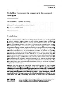
This table 3 shows that for the same part manufactured, it is possible to reduce the environmental impact of the process choosing the best strategy. For instance, concerning the motor axes, it is shown that the strategy called ”ZigZig” consume the triple of electrical energy due to the high acceleration commanded. Nevertheless, this consumption is balanced by the electric consumption of the laser which is less important in this strategy. In fact, the laser is switch off during the way back reducing its consumption. Furthermore, this strategy is slower than the ”ZigZag” strategy. In fact, many time (around 1 hour) is spent in the way back where no material is fused. This table table also shows that the strategy ”ZigZig” consume 11% more material than the other. From this values and the characterization factors (table 2) the environmental impact of each strategy is computed. The figure 19 shows that if the study is focused only on electrical consumption, the strategy called ”ZigZag” has a same environmental impact than the other strategy. However, taking into account fluids and material consumption, the environmental impact of the strategy ”ZigZag” become less important. The difference between both strategies (20 mPts)
Sustainable manufacturing: Evaluation and Modeling of environmental impacts in additive manufacturing21 Environmental impact of different flows
600
ZigZag ZigZig
Environmental Impacts [mPts]
500
400
300
200
100
0
Electricity
Fluids
Material
Total
"ZigZag"
"ZigZig"
E.I.electricity = 401 mPts
E.I.electricity = 402 mPts
E.I.fluids = 27 mPts
E.I.fluids = 31 mPts
E.I.material = 119 mPts
E.I.material = 134 mPts
E.I.total = 547 mPts
E.I.total = 567 mPts
Fig. 19 Environmental impact assessment
is equivalent to the production of around 10 kg of secondary aluminum. This study shows that it is not judicious to focus the environmental impact only on electrical consideration but studies have to be focused on each product (material, fluids, electricity) which contribute to the environmental impact. In the field of environmental impact assessment this is called impact transfer. In fact, if the study is focus only on one specific consumption, the impact of another flow consumption could be neglect.
6 Conclusion The authors propose a new methodology in order to evaluate, with accuracy, the environmental impact of a part from its CAD model. In this methodology, the work is not focused only on electrical consumption but also on fluids and material consumption. In fact, just as in life cycle assessment, it is important to take into account all the products which contribute to the environmental impact and it is not judicious to consider only the electrical consumption in such a study. In addition, in this methodology the authors used the set of part-process which allow to take into account different manufacturing strategies and their influences on the global environmental impact. All this aspects are shown in the example. The methodology developed is based on both analytic models (validated by experiments) and experimental models.
22
Florent Le Bourhisa,c et al.
Thereafter, the work on the method will be pursued in order to be able to generate automatically manufacturing strategies minimizing the environmental impact of a part. Moreover, a study of robustness and sensibility will be done on the methodology.
References 1. Le Pochat, St´ephane (2005) Ecodesign integration in SMEs Proposal for a know - How appropriation method for environmental product design, pp.279. PhD Thesis, Ecole Nationale Sup´erieure des Arts et M´etiers de Paris. 2. ADEME (2009) Carbon footprint : an indispensable tool. http://www.ademe.fr/htdocs/publications/dossier/av21/p1.htm. Accessed 10 May 2012. 3. Vargas Hernandez N, Okudan Kremer G.E, Schmidt L.C, Acosta Herrera P.R (2012) Development of an expert system to aid engineers in the selection of design for environment methods and tools. Expert Systems with Applications 39 (2012) : 9543–9553. doi: 10.1016/j.eswa.2012.02.098 4. Bourell D.L, Leu M.C, Rosen D.W (2009) Roadmap for additive manufacturing - Identifying the future of freeform processing, pp.32. The University of Texas at Austin, Laboratory for Freeform Fabrication, Advanced Manufacturing Center 5. Hague R, Tuck C (2007) ATKINS : Manufacturing a Low Carbon Footprint - Zero Emission Enterprise Feasibility Study. Loughborough University 6. Munoz A.A, Sheng, P (1995) An analytical approach for determining the environmental impact of machining processes. Journal of Materials Processing Technology 53 (1995) : 736–758 7. Dahmus J.B, Gutowski T.G (2004) An Environmental Analysis of Machining. In: ASME International Mechanical Engineering Congress and RD&D Expo, Anaheim, California, USA, pp 1–10 8. Pusavec F, Krajnik P, Kopac J (2010) Transitioning to sustainable production - Part I: application on machining technologies. Journal of Cleaner Production 18 (2010) : 174–184. doi: 10.1016/j.jclepro.2009.08.010 9. Pusavec F, Kramar D, Krajnik P, Kopac J (2010) Transitioning to sustainable production - part II: evaluation of sustainable machining technologies. Journal of Cleaner Production 18 (2010) : 1211–1221. doi: 10.1016/j.jclepro.2010.01.015 10. Avram I.O, Xirouchakis P (2011) Evaluating the use phase energy requirements of a machine tool system. Journal of Cleaner Production 19 (2011) : 699–711. doi: 10.1016/j.jclepro.2010.10.010 11. Kong D, Choi S, Yasui Y, Pavanaskar S, Dornfeld D, Wright P (2011) Software-based tool path evaluation for environmental sustainability. Journal of Manufacturing Systems 30 (2011) : 241–247. doi: 10.1016/j.jmsy.2011.08.005 12. Luo Y, Ji Z, Leu M.C, Caudill R (1999) Environmental performance analysis of solid freeform fabrication processes. Institute of Electrical and Electronics Engineers (1999) : 1–6 13. Sreenivasan, R, Goel, A, Bourell D.L (2010) Sustainability issues in laser-based additive manufacturing. Physics Procedia 5 (2010) : 81–90. doi: 10.1016/j.phpro.2010.08.124 14. Mognol P, Lepicart D, Perry N, (2006) Rapid prototyping: energy and environment in the spotlight. Rapid Prototyping Journal 12 (2006) : 26–34. doi: 10.1108/13552540610637246 15. Kellens K, Yasa E, Renaldi, Dewulf W, Kruth J.P, Duflou J.R (2011) Energy and resource efficiency of SLS/SLM processes. In: Solid Freeform Fabrication Symposium Proceeding, The University of Texas at Austin, USA, pp 1–16 16. Baumers M, Tuck C, Hague R, Ashcroft I, Wildman R (2010) A comparative study of metallic additive manufacturing power consumption. In: Solid Freeform Fabrication Symposium Proceeding, The University of Texas at Austin, USA, pp 278–288 17. Goedkoop M, Spriensma R (1999) The Eco-Indicator 99 Methodology. PR´e Consultants B.V. 18. Ponche R, Hascoet J.Y, Kerbrat O, Mognol P (2012) A new global approach to design for additivemanufacturing. Virtual and Physical Prototyping 7 (2012) : 93–105. http://dx.doi.org/10.1080/17452759.2012.679499 19. Muller P, Mognol P, Hascoet J.Y (2013) Modeling and control of a direct laser powder deposition process for Functionally Graded Materials (FGM) parts manufacturing. Journal of Materials Processing Technology 213 (2013) : 685-692. http://dx.doi.org/10.1016/j.jmatprotec.2012.11.020