ALBERTAZZI JR., A. G.; PEIXOTO FILHO, F. T.; SUTERIO, R; AMARAL, F. K. – “Evaluation of a Residual Stresses Measurement Device Combining a Radial In-Plane ESPI and the Blind Hole Drilling Method” – SPIE - The International Society for Optical Engineering, Europe International Symposium Photonics, Strasbourg, France, 26-30 April, 2004.
Evaluation of a Residual Stresses Measurement Device Combining a Radial In-Plane ESPI and the Blind Hole Drilling Method Armando Albertazzi G. Jr.(a), Flávio Tito Peixoto Filho(a), Ricardo Suterio(b), Felipe Kleber Amaral(a) (a)
Federal University of Santa Catarina Cx. Postal 5053 - CEP 88.040-970 - Florianópolis, SC - Brazil. e-mail:
[email protected] (b)
National Institute for Spatial Research Cx. Postal 515 - CEP 12.227-010 - São José dos Campos, SP - Brazil. e-mail:
[email protected] Keywords: ESPI, Interferometry, Radial Interferometer, Residual Stresses Measurement
ABSTRACT A new kind of electronic speckle pattern interferometer was developed by the authors’ group using conical mirrors to measure the radial in-plane displacement component. True radial in-plane sensitivity is achieved by double illumination ESPI. A compact version of this interferometer was designed and built and successfully tested outside of an optical table. This paper presents a measurement evaluation of a second generation of this interferometer applied to residual stresses measurement. An ultra high-speed drilling unit was added to the device to drill a small blind hole in the region of interest. Due to the drilling process residual stresses are released in the neighborhood of the hole. The resulting radial displacement field is conveniently measured by the radial in-plane interferometer and fitted to a mathematical model. The principal residual stresses and principal stresses directions are then determined. One main difficulty dealing with evaluation of a residual stresses measurement device is to obtain a standard with a well known reference value. Two mechanical devices where built to provide a reference residual stresses value. The first one is a long specimen under a known uniform stresses field. The second one is a long pipe with known internal pressure. Both were designed, built and calibrated to provide a reference residual stresses value to calibrate the built residual stresses measurement device. Results of the evaluation of this device are also presented in detail in this paper. Both devices where used to check the measurement performance of the developed residual stresses measurement system and the results are presented and discussed in this paper.
1. INTRODUCTION Mechanical stress is a very important quantity to determine how close a material is to its failure limits. Most analytical and numerical calculation methods are applied to correctly design a mechanical component in order to keep it working in a safe condition, far from the failure stresses limits. In very complex mechanical parts or loading conditions experimental stress analysis methods are used instead of analytical or numerical methods to verify the real working conditions of a mechanical component or system. A very dangerous kind of mechanical stresses are the residual stresses. They are developed during the manufacturing process specially when welding, forging, and casting or when heat treatment are involved. Residual stresses can be present even in the absence of any external mechanical loading. They are very dangerous because they are combined with mechanical stresses and the resulting combined level can exceed the failure limit. As a result, the mechanical component can fail unexpectedly, without any prior advice. They are very difficult to be calculated by analytical or
numerical methods since the knowledge of the material history have to be precisely known. Frequently, residual stresses are experimentally measured. The most used technique is the hole drilling strain gage method, standardized by ASTM E 837.1,2,3 Electronic Speckle Pattern Interferometry (ESPI) has been successfully used for several years in many applications in the experimental mechanics field to measure mechanical stresses. Two sets of images are grabbed, one in the reference loading stage and the other in the final loading stage. A phase pattern is computed for each stage and the phase difference is calculated for each pixel of the image. After some image processing, the displacement field between the two loading configurations is computed for the whole image. From spatial derivatives of that, the strains can be computed and then, the stresses can be determined. ESPI can be applied with single or double illumination. Usually, a single illumination configuration is more suitable to measure the out-of-plane displacement component. Double illumination is more appropriate to measure the in-plane displacement component in one direction. For a complete in-plane strain measurement, at least two double illumination setups are required and their measurement results have to be combined. Each illumination condition leads to a different phase difference pattern that have to be processed and carefully combined in order to compute the full in-plane results, what can bring some additional practical difficulties. A new kind of ESPI interferometer was introduced in the authors’ group: a radial in-plane (RIP) interferometer4,5,6,7. It is basically a double illumination interferometer with in-plane radial sensitivity. It can be used to measure, with a single image, the complete in-plane displacement and strains in a point of interest. The strain and stress states can be easily determined for the central point of the measured region. A very potential application for this new RIP interferometer is residual stress measurement combining ESPI with the blind hole drilling method. This paper presents some developments in that field and the second generation of a compact device that was built to measure residual stresses. Since its design leaded to a very compact and stiff device, it has been successfully used outside of an optical bench.
2. PRINCIPLES OF THE RADIAL IN-PLANE INTERFEROMETER Figure 1 shows the main scheme of the radial in-plane (RIP) interferometer. The laser light is expanded and collimated and reaches a 45° mirror that directs the collimated light towards a conical mirror. The reflected light beams are directed to a central circular area on the specimen surface were double illumination takes place. It can be verified that true radial sensitivity is obtained in this circular region. The 45° mirror has a hole in it that has two main functions: (a) to avoid triple illumination, i.e., to guarantee that only the two light components reflected by the conical mirror reach the specimen surface located in the central part of the conical mirror and (b) to promote a viewing window to the imaging system. In central part of the measurement area there is a singular point that receives light from all angles. It is particularly shining and can blur the remaining image. In order to reduce this effect, the conical mirror was split in two parts, and a small gap was left between both parts. The gap is positioned in such a way that the light rays that would be reflected to the middle are blocked. As a consequence, a small circular shadow is developed in the middle of the area illuminated by the conical mirror and image blurring is avoided. A piezoelectric actuator is introduced between both parts of the conical mirror to phase shift the image. By slightly increasing the gap between the lower and the upper parts of the conical mirror, there is a small optical path change between both light rays that merge to double illuminate each point. Since collimated light is used, it can be verified that the optical path change is exactly the same for each point of the illuminated surface. So, by slightly changing the gap between both parts of the conical mirror, it is possible to phase shift the image by a constant amount.
Figure 1 - Basic configuration of the radial in-plane (RIP) interferometer If a uniform stress field is applied to the measured region, the radial displacement field (ur), can be derived from the linear stress-displacement relation. So, can be written in polar coordinates (ρ, θ), like following equation:5,7 u r (r , θ ) =
(1 − υ ) r (σ + σ ) 1 2
+
2E
(1 + υ ) r (σ − σ ) cos(2θ − 2 β ) 1 2 2E
(1)
where: r, θ σ1, σ2 E
υ β
are polar coordinates where; are the principal residual stresses (maximum and minimum respectively); is the Young modulus of the material; is the Poisson ratio of the material; is the principal direction.
In order to measure residual stresses a small hole has to be drilled in the measurement area center. A mathematical model for this problem was developed by Kirsch8 based on the elastic solution for an infinite plate, subjected to a uniform state of stresses, where a cylindrical hole is drilled all way through the plate thickness. The radial component of the displacement field (ur), developed by the hole drilling can be described in polar coordinates by the following equation:4,5,7,10
(
)
(
)
u r (ρ , θ ) = A( ρ ) σ 1 + σ 2 + B ( ρ ) σ 1 − σ 2 cos(2θ − 2 β )
(2)
where the functions A(ρ) and B(ρ) are given by: A( ρ ) =
and,
ρ, θ ro
(1 + ν ) r 2E
0
ρ
B( ρ ) =
1 2E
[
r0 4 ρ − (1 + ν )ρ 3
]
r are polar coordinates where ρ is the normalized radius (ratio between r0 and r), ρ = o ;. r is the drilled hole radius.
(2b)
Makino and Nelson verified that it is necessary to take into consideration the limited depth of the drilled hole10. By means of finite element calculated coefficients the residual stresses versus displacement relations must be modified when a blind hole is done. So, the equation (2) can be rewriten to: u r (ρ , θ ) = A a ( ρ )
(σ1 + σ 2 )
+
B b( ρ )
(σ1 − σ 2 )
cos(2θ − 2 β )
(3)
where A and B , are constants given by: A=
1 +ν
B=
ro
1
ro 2E 2E and a ( ρ ) and b ( ρ ) , are functions given on the table 1, bellow.
(3a)
Table 1 - Makino and Nelson correction coefficients for radial displacements measurements. 1
ρ
r r0 1.5 2.0 2.5 3.0 3.5 4.0 5.0 6.0 =
a( ρ )
b( ρ )
0.6808 0.5073 0.3943 0.3136 0.2534 0.2073 0.1456 0.1069
1.8626 1.4170 1.0870 0.8517 0.6792 0.5512 0.3854 0.2865
Equation (1) can be used to compute mechanical stresses from the radial in-plane displacement field in a specimen submitted to a uniform stresses state. The measured displacement field can be fitted to equation (1) using least squares. Alternatively, the radial displacement field can be measured all way along a sampling circle, with radius ρ, concentric with the center of the measurement area, as shows Figure 2. The radial displacement field, measured along the entire sampling circle (360°), is a periodical signal. By Fourier analysis, it is possible to separately quantify the zero order (H0) and second order (H2) harmonics. Then, the three unknowns of equation (1) can be solved and the principal stresses and direction can be directly computed by the software.
Figure 2 - Processing analyses area, sampling circle, and the principal direction stress.
In a residual stress measurement problem usually the material constants (E, υ) are sufficiently known. The radius of the drilled hole (ro) can be experimentally measured. Since the radial displacement field (ur), can be measured for several thousand points as a function of ρ and θ, only three variables remain unknown: the principal residual stresses σ1, σ2 and the principal direction β. Also here a least squares approach and a harmonic base equation can be used to compute these three unknowns.
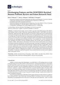
3. THE PORTABLE MEASUREMENT DEVICE A portable measurement device is shown in figure 3. It consists of three parts: a drilling head, a universal base, and a measurement head. The drilling head has an ultra high-speed pneumatic drilling unit that can also be positioned in the universal base. Height adjustment makes it possible to clam this device in virtually any surface. The universal base is rigidly clamped to the specimen surface by rare earth magnets and three feet with sharp conical tips to reduce the relative motion between the base and the specimen surface. The measurement head has a diode laser inside and a TV camera capable to acquire images. It is fixed to the universal base through a kinematic interface that makes it possible to precisely reposition it as many times as necessary.
Figure 3 - Portable measurement device and radial in-plane (RIP) interferometer
4. RESIDUAL STRESSES CALIBRATION To calibrate any measurement system it is necessary to compare its results with a reference value. Two calibration techniques are usual: direct and indirect calibration. In the indirect calibration the same measurand is simultaneously measured by the calibrated measurement system and a reference measurement system capable to produce uncertainties at least ten times better than the calibrated one. The reading differences are assigned to be due to measurement errors of the calibrated measurement system. In the direct method, a very well-known measurand is used – a calibration standard. The output of the calibrated measurement system is then compared with the reference value of the calibration standard and the differences are assigned to be measurement errors of the calibrated measurement system. These calibration techniques are also valid for calibration of residual stresses measurement devices. However, it is very difficult to obtain a residual stresses reference standard. It is also not easy to find a reference residual stresses measurement technique with measurement uncertainty ten times better than the calibrated device. To overcome this difficulty two alternative ways were used in this work: mechanical simulation and redundancy check.
4.1 ONE-AXIS RESIDUAL STRESS SIMULATION DEVICE
It is possible to produce a reference residual stresses equivalent value by mechanical simulation. The main idea is to release the pre-existing residual stresses by annealing a geometrically well-defined specimen and apply a very wellknown mechanical stress state. The final effect is equivalent to have a specimen with known residual stresses. Since it is easer to produce a well-known mechanical stress state than a well-known residual stresses state, this is a good approach. However, it is necessary to take into consideration several uncertainty sources that can affect the degree of confidence in the simulated stress field. The quality of the loading device, geometric errors in the specimen, material anisotropies, residual stresses not properly released are the main uncertainty sources. Figure 4 shows the first attempt to develop a one-axis residual stresses simulation device. It consists of a three meters steel laminated beam specimen tensioned through its edges. This beam is made of low carbon steel (0,20 %) and was submitted to a residual stress-relief heat treatment by annealing. On this beam surface, ten strain gauges were positioned (figure 4b) to produce the reference values used to verify the amount and uniformity of the applied strain. These strain gauges are connected to a bridge amplifier with a serial communication to a computer where the strain values can be viewed and stored. Three bolts in each side of the device can be griped independently in order to load the specimen. The same specimen length is long enough to accommodate few hundreds of measurement points using the hole drilling method. A minimum distance of ten times the hole diameter is left between each drilled hole.
Figure 4 - (a) the uni-axial stress simulation device (b) strain gauges positions
This device can only simulate one-axis stress states. In this case, the loading force acts in a single direction, through the length of the beam. This is a good starting point, however it does not represent what occurs at most of field applications. Hence, the laboratory team developed another device capable to simulate bi-dimensional stresses states [11]. 4.2 THE BI-DIMENSIONAL RESIDUAL STRESSES SIMULATION PIPE
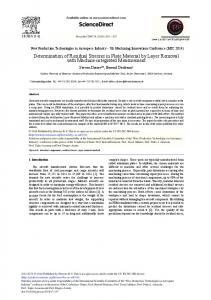
This second device was constructed from a pipe originally used for oil transportation. This pipe had its edges sealed by flanges and got filled with water. One of the pipes has a mouth where a hose passes through. A pump injects oil in the
hose that acts over the water pressurizing the pipe. A manometer indicates the pressure and by this way an analytical value for the loading stresses over the pipe can be determinate. See scheme in figure 5 and the device in figure 6.
Figure 5 - Hidraulic scheme for loading the pipe with known internal pressure
Along the pipe’s external surface eight 90o strain gauges rosettes were carefully positioned. As the same way as the first stress simulation device’s strain gauges, these rosettes are connected to the bridge amplifier that communicate with the computer. The measurement system under evaluation is also positioned on the pipes’ external surface.
Figure 6 - Experiment in progress (a) interferometer positioned on the pipe (b) a close view of the interferometer
This configuration was selected not only because it is possible to simulate a bi-dimensional stresses field but also due to the huge interest of the oil and gas industry to this residual stress measurement device. This pipe brings field characteristics to laboratory environment, allowing a more complete evaluation, next to the desired measurement situation. The pipe is three meters long, has a 508 mm external diameter and its thickness has 9.5 mm. Its composition is the API 5L b steel with a 294 MPa yield strength. Since no heat treatment was possible to apply in this tube to anneal the preexisting residual stresses, the mechanical stress state can not be assumed to simulate a residual stresses reference state. It cannot be assumed to be a residual stress standard. However, it can be used to verify the measurement system’s results using redundancy. This process is described in section 5.
5. EXPERIMENTAL PROCEDURES The experimental calibration procedures are different between the two residual stress simulation devices. But in both case the optical system must be positioned, clamped and its stiffness verified. That is done through the universal base.
The operation of the one axis residual stresses simulation device requires few steps. First the mechanical loading is completely removed by releasing the loading bolts. The long specimen has to rest on several supports to minimize stresses induced by gravity effects. The measurement bridge amplifier is adjusted in such a way that all indications of the strain gauges are zero. Then, the load is applied by griping the bolts. The amount and uniformity of the applied stresses field are controlled by reading the indicated strains in the ten strain gauges. By an interactive process each of the six bolts are the adjusted to produce a final well-known uniform stress state. This mechanical stress state is assumed to be equivalent to the existing residual stress state. The loaded device is kept in this state while the residual stresses measurement device is installed on its surface and a residual stresses measurement is done by hole drilling. A set of four 90° phase-shifted images are acquired and an unwrapped phase pattern is computed and saved as a reference state. A blind hole is drilled and another unwrapped phase pattern is computed. The phase difference is unwrapped and processed to compute the residual stresses state. Since the amount of pre-existing residual stresses is negligible, the reference value of residual stresses can be compared with the stresses computed from the strains indicated by the strain gauges. The two-dimensional residual stresses simulator can not be used in the same way. Since the pipe could not be annealed the amount of pre-existing residual stresses cannot be disregard. This means that the amount of mechanical stresses applied by internal pressure can not be compared with the measured residual stresses. So, to partially verify the performance of the residual stresses measurement device a redundancy test was made. To do that, a four steps procedure was adopted as shows figure 7. In step one a reference unwrapped phase pattern is acquired with no pressure on the pipe. Only the pre-existing residual stresses are present. In step 2 the internal pressure is applied to the pipe until the target value is reached and a second unwrapped phase pattern is acquired. The mechanical stresses field due to internal pressure is added to the pre-existing residual stresses. In step 3 a blind hole is drilled and another unwrapped phase pattern is acquired. Finally, in step 4 the internal pressure of the pipe is released and the fourth and last unwrapped phase pattern is acquired.
Loading
1
Hole Drilling
2
Unloading
3
4
Step 1: pre-existing residual stresses only Step 2: pre-existing residual stresses + mechanical stresses Step 3 pre-existing residual stresses + mechanical stresses + hole drilled Step 4: pre-existing residual stresses + hole drilled. Figure 7 - The four steps used in the redundancy procedure
The phase difference between steps 1 and 2 is related to the mechanical loading only (σM) and can be processed and fitted to equation (1) to obtain the mechanical stresses. The phase difference between steps 2 and 3 is related to the hole drilling process only and, after processing and fitting to equation (3) can produce the combine stresses (σC) the results from the addition of the mechanical stresses (σM) and the pre-existing residual stresses (σP). Finally, the phase difference between steps 1 and 4 is equivalent to the hole drilling measurement that, when fitted to equation (3), produce only the pre-existing residual stresses (σP). It is easy to notice that the following relation should be satisfied:
σ
C
=σ
M
+σ
P
(5)
So it is possible to experimentally verify if the above equation is fulfilled. It is not a calibration, but can be used to verify by redundancy if the combined and pre-existing measured residual stresses agree with the applied mechanical stresses.
6. MEASUREMENTS RESULTS Two sets of experiments were carried out using both residual stresses simulation devices. The next two sub-sections describe the results of both experiments. 6.1 ONE-AXIS RESIDUAL STRESS SIMULATION DEVICE
The long beam specimen was first loaded until the strain gauges indicate a mean strain value close to 400 µm/m. The bolts were adjusted to produce a near uniform strain state. After this operation the mean value was 388,3 µm/m and the readings of the ten strain gauges. The strain gauges measurements can be seen in table 2. Table 2 – Strain gauges measurements 1 367,2
2 366,4
3 393,8
4 370,4
5 381,5
6 405,8
7 406,6
8 384,1
9 405,5
10 403,0
Then the residual stresses measurement device was positioned on the long specimen and a reference unwrapped phase pattern was acquired. A 1.8 mm diameter blind hole was drilled and another unwrapped phase pattern was acquired.
Figure 8 - Residual stresses fringe patterns: (a) original phase difference and (b) processed one.
The resulting fringes (figure 8) were processed by the software using three different algorithms: least squares, harmonics and least squares using Makino and Nelson coefficients10. The last two use Passing Through Hole method from equation (2), and the last one uses Blind Hole correction coefficients from equation (3) and Makino and Nelson coefficient to displacement measurements. Their results are described below. Table 3 – Results using Least Squares method and equation 1 (Passing Through Hole)
σ1 [MPa] 90,8
σ2 [MPa] 25,6
ε1 [µm/m] 402,1
ε2 [µm/m] -5,9
β [o] 30,2
ratio ε2/ε1 -0,0146
Table 4 – Results using Harmonic method and equation 1 (Passing Through Hole)
σ1 [MPa]
σ2 [MPa] 88,4
ε1 [µm/m] 26,8
β [o]
ε2 [µm/m] 389,0
3,3
30,4
ratio ε2/ε1 0,0084
Table 5 – Results using Least Squares method and Makino and Nelson coefficients from equation 2 (Blind Hole)
σ1 [MPa]
σ2 [MPa] 96,6
ε1 [µm/m] -1,3
ε2 [µm/m] -144,0
468,6
β [o] 30,2
ratio ε2/ε1 -0,307
Comparing the principal strains values, the method of harmonics’ results are the closest to the strain gauges mean value. However, since the measurement was made at a point very near to strain gauges 9 and 10, the minimum squares algorithm did it nice as well. The Makino and Nelson algorithm returned the farthest result from the mean strain, however the main stresses σ2 is almost zero, what is expected, and the ratio ε2/ε1 results in a value very close to the material’s Poisson ratio (0,295). It must be clarified that the principal angle (β) is measured against a reference that is 30° rotated to the specimen axis. It is necessary to subtract 30° from the values on the table to correctly get the principal stresses direction. 6.2 BI-DIMENSIONAL RESIDUAL STRESSES SIMULATION PIPE
For this experiment the four steps procedure described in the last section was applied. The phase difference patterns and their respective computed stresses due to mechanical loading (σM), pre-existing residual stresses (σP) and combined stresses (σC) are related below. Once the main stresses directions are different at each case, the residual and combined stresses table also shows the stress components at the loading direction (σx e σy). These values are used for the redundancy check. Table 6 – Loading stresses at the Bi-dimensional Residual Stresses Simulation Pipe experiment
Loading Stresses (σM) σ1 [MPa] σ2 [MPa] 136,0 75,9
β [o]
ε1 [µm/m] 25,8
550,0
ε2 [µm/m] 178,7
Table 7 – Residual stresses at the Bi-dimensional Residual Stresses Simulation Pipe experiment
Residual Stresses (σP) σ1 [MPa] σ2 [MPa] 44,56 15,99
β [ o] 148,7
σx [MPa] 24,4
σy [MPa] 36,1
Table 8 – Combined stresses at the Bi-dimensional Residual Stresses Simulation Pipe experiment
Combined Stresses (σC) σ1 [MPa] σ2 [MPa] 139,8 82,1
β [o] 17,8
σx [MPa] 138,7
σy [MPa] 83,2
Table 9 shows the 90o rosettes mean results. Table 9 – Residual stresses using 90o strain gauges rosettes
σ1 [MPa] 131,8
σ2 [MPa] 71,2
ε1 [µm/m] 536,1
ε2 [µm/m] 161,7
Figure 9 - Fringe patterns (a) loading stresses, (b) residual stresses, (c) combined stresses
The results show that the loading stresses and its respective strains measured by the system are very close to the strain gauges values. However, it can be seen on the next table that the redundancy check between these loading stresses and pre-existing residual and combined stresses was not fully satisfied. A remaining error of about 20% was detected, what is usually acceptable for this kind of measurement. The poor image quality was probably the main reason for that difference. Future efforts will be directed to detect the main error sources and to minimize their effects. Table 10 – Four steps analysis
σP + σM σ1’ [MPa] 160,4
σC σ2’ [MPa] 112,0
σP + σM – σC
σ1 [MPa] 138,7
σ2 [MPa]
σ1 [MPa] 83,2
σ2 [MPa] 21,7
28,8
7 CONCLUSIONS 7.1 FUNCTIONAL EVALUATION
A new kind of mechanical and residual stresses measurements system was presented. In laboratory environment this device was very practical and easy to use. The time necessary to measure residual stresses is about ten times faster than what is required when strain gauges rosettes are used. Almost no surface preparation is required. The acquisition and processing time is very short. However, some experience and measurement skills are necessary at the current development stage to successfully measure residual stresses. Modifications are being made to minimize the need for user interventions. Additionally, tests in situ are being planned to verify the system’s field applicability, under temperature variations and vibrations. 7.2 METROLOGICAL EVALUATION
Both devices used to evaluate the measurement performance of the developed residual stresses measurement system seemed incorporate advantages and disadvantages. The first one is uniform and has its proprieties well defined but it simulates just a very specific stress state. The second one simulates bi-dimensional stresses and incorporates characteristics that the system will face at field applications, but it cannot be considered a stress standard once its stress profile is not uniform and cannot be easily defined.
The results of the experiment with the beam agree with what was expected, a little deviation was found but can be future corrected with an algorithm correction. The experiment with the pipe generated good loading results, very close to the strain gauges rosettes values, even though the relation between loading, residual and combined stresses was not fully satisfied. Further work will be directed to minimize the effects of some known error sources, especially improving the image quality by a different model of diode laser and its driver.
8 ACKNOWLEDGEMENTS The authors are grateful to the following institutions: ANP – Agência Nacional de Petróleo, CNPq – Conselho Nacional de Pesquisa e Desenvolvimento, FINEP – Financiadora de Estudos e Projetos, CTPETRO, PETROBRÁS/CENPES, TBG, UFSC and the whole Labmetro’s technical staff.
9 REFERENCES 1.
ASTM E 837-01, “Determining Residual Stresses by the Hole Drilling Strain Gage Method”, ASTM Standard American Society for Testing and Materials, 2001.
2.
R. E. Row Lands “Residual Stresses” in “Handbook on Experimental Mechanics” edited by Kobayashi, A. S., Prentice-Hall Inc, New Jersey, USA, pp. 768-813, 1987.
3.
Dr. Jean Lu, “Handbook of Measurement of Residual Stresses”, Society for Experimental Mechanics Inc., The Fairmont Press Inc., 1996.
4.
Rodacosky, M. R. “Residual Stresses Measurement with ESPI” (in Portuguese), Dr. Eng. Thesis at the Federal University of Santa Catarina, 1997.
5.
Albertazzi Jr., A., Kanda, C., Borges, M. R., Hrebabetzky, F., "A portable residual stresses measurement device using ESPI and a radial in-plane interferometer", Proc. SPIE Vol. 4420, p. 112-122, Laser Metrology for Precision Measurement and Inspection in Industry; Armando Albertazzi, Jr.; Eds. Sep 2001.
6.
Albertazzi Jr., A.; Willemann, D. P.; Veiga, C. L. N., “Preliminary evaluation of the Optical Rosette – a portable device for stress measurement with SPIE” in 7th Symposium on Laser Metrology Applied to Science, Industry and Everyday Life – Novosibirski / Russia, p.1073-1084, September 09-13, 2002.
7.
Albertazzi Jr., A.; Willemann, D. P.; Veiga, C. L. N., “Evaluation of the Optical Rosette for translation, stresses, and stress gradient measurement”, Proc. SPIE Vol. 5144, p. 533-544, Optical Measurement Systems for Industrial Inspection III; Wolfgang Osten, Malgorzata Kujawinska, Katherine Creath; Eds. May, 2003.
8.
Kirsch, G., “Theory of Elasticity and Application in Strength of Materials” in “Zeitschrift Verein deutscher Ingenieure”, No 29, 797-807, 1898.
9.
Rendler, N.J. and Vigness, I., “Hole-Drilling Strain-Gage Method of Measuring Residual Stresses”, Experimental Mechanics, 12 (6), 1966.
10. Makino, A.; Nelson, D., “Residual-Stress Determination by Single-Axis Holographic Interferometry and Hole Drilling – Part I: Theory”, Experimental Mechanics, p. 66-78, March, 1994. 11. Peixoto F., Flavio Tito, Albertazzi Jr., Armando, Sutério, R., Bigarella, F. "A Residual Stresses Simulation in Pipes Device Development"(in Portuguese), in: Metrologia 2003, Florianópolis, Brazil, September 01-05, 2003.