Aacheq Germany, 2004
2004 35th Annual IEEE Power Eleclronics SpecialisIs Conference
Evaluation of Embedded Heat Extraction for High Power Density Integrated Electromagnetic Power Passives J.Duker Department of Mechanical Engineering7 Rand Afrikaans University, South Africa Email:
[email protected]
W.Liu Center for Power Electronic Systems, Virginia Polytechnic Institute and State University, United States of America Email: weliu6@vt,edu
J.D.Van Wyk Center for Power Electronic Systems, Virginia Polytechnic Institute and State University, United States of America Email:
[email protected]
Abstract- The use of embedded solid-state heat extractors to increase the power densities in power electronic modules seems promising. Cross-sectional geometric optimisatioo was done on heat extraction iusert and it was found that the most suitable heat extraction configuration for application in power electronics is the use of flat continuous heat extraction layers aiding in conducting heat to externally mounted heat sinks. Theoretic expected thermal enhancement factors were determined and experimentally verified. Interfacial thermal resistances adversely influence the eflectiveness of heat extraction inserts and should be minimised.
I.
INTRODUCTION
The integration technology for power electronic converten for the future requires the ability to integrate electromagnetic power passives to achieve high overall power densities [l]. Considerable work has been done to develop and optimise the material processes and electromagnetic design to increase the power density to some 20W/cm3 at 1 h4Hz. However, from the study of the limits of this technology [2,3], it is clear that the thermal limitations of the structure have to be addressed to increase the power density. Although the loss density is much lower than found in power semiconductor devices, the corresponding lower thermal conductivities of the ceramics used in these structures lead to thermal limitations. A recent study has shown the feasibility of improving the thermal behaviour of such structures by embedded solid heat extraction in the structures [4]. The presence of heat extractors can lower operating temperatures dramatically. Suitable heat extraction materials include those with a relatively high thermal conductivity and a low electrical conductivity such as beryllium oxide with a thermal conductivity in the region of 270 W/mK, aluminium nitride with a thermal conductivity in the region of 170 W/mK, and synthetic polycrystalline diamond with a thermal conductivity in the region of 2300 W/mK. As a first step of implementing heat extractors it was decided to study the outer femte layers [2,3] of integrated electromagnetic power passives. Embedding heat extracting material reduces the cross sectioned area of the active magnetic material, but on the other hand enables the increase of the flux density leading to an opportunity for optimisation. In order to implement this, it is not only necessary to embed heat extraction material of the correct shape and thermal conductivity into the structure, but also control the
0-7803-83')9-0/04/$20.0002004 IEEE.
z
J.P. Meyer Department of Mechanical and Aeronautical Engineering, University of Pretoria, South Africa Email:
[email protected]
Heat extrachon
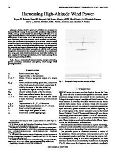
Fig. 1. Optimum heat extraetion gcomcuy whae less than 10% ofthc volume is occupicd by heat cxuactors
thermal interface resistance to ensure the success of the method. This paper reports on the theoretical analysis of a proposed structure and the optimisation of the increased flux density in the core material. The determination of actual practical thermal contact resistances, the properties of thermal adhesives, an experimental structure to evaluate the theoretical projections, and an improved integrated electromagnetic power passive module is discussed. 11.
THEORETICAL ANALYSIS
For two-directional heat extraction from a medium with a low thermal conductivity in the region of 2 - 5 W/mK, such as ferrite, it was found through a numerical optimisation investigation that for cases where less than 10% of the total volume is occupied by the heat extractors, the optimum cross sectional shape of solid state embedded heat extractors is that of continuous flat layers as shown in Fig. I [4,5]. Furthermore it was also found that for structures in the size range of interest in power passives, the advantage of optimising the cross sectional area geometry of the heat extractors almost diminishes as dimensions become smaller. It would thus only be of interest to consider heat extraction geometries that are easily manufactured, such as flat continuous layers. Heat extracted in this way can be directed to heat sinks from where it can be disposed of to the environment.
4888
Aachen,
2004 35th Annual IEEE Power Elecaonics Specialists Conference
Germany, 2004
performance. The higher C,,, the better equipped the structure is to conduct heat to the heat sink. INFLUENCE OF INTERFACM THERMAL RESISTANCES It was important to determine the influence of the thermal interface resistances on the effectiveness of embedded heat extractors. Several case studies were conducted. For a given case with a specified maximum operating temperature, the allowable increase in local heat generation density that could be sustained due to the presence of heat extractors can be determined. For a case where 31=2.5mm and a=0.1 with aluminium nitride (kc I 170 W/mK) embedded into femte (kM I5 W/mK), the allowed increase is shown in Fig.3 for a wide range of interface resistances. In the idealised case where no interface thermal resistances are present, an expected increase of 425% in heat generation density can be supported. However, as R , or R i , increases, the thermal advantage of inserting heat extractors quickly diminishes. Interfacial resistances are thus a critical factor for the effective operation of embedded heat extractors and if these are too great it will nullify the advantage of using heat extractors. Similar shaped graphs were obtained for a wide range of different input values. 111.
Heat
i,
Internal thermal interface i a n w , R,,
Fig. 2. Reprcscntative domain used for the numerical modcl.
In order to investigate the thermal performance of such an arrangement, a two-dimensional finite difference numerical model was created. The representative domain used for this purpose with its boundary conditions is shown in Fig.2. Dimensions li and Z are defined in the figure. The thermal conductivity of the heat generating material and heat extractors are given by kM and kc [W/mK] respectively. Thermal interface resistances, Rin, and R,, [m2K/W] were defined on the interface between the heat generating medium and the heat extractor, and along the entire contact length of the isothermal heat sink respectively. The volume fraction occupied by the heat extraction layers in terms of the total volume can be expressed by c
The steady-state temperature distribution within the representative domain was solved by means of a fully implicit finite difference numerical scheme. A uniform mesh of nodal points was generated in the both the heat generating as well as the heat extraction regions. The same P-directional spacing was used in both these regions while each region had its own constant y directional spacing. No nodes were defined on the interfacial surfaces as this frequently resulted in discontinuity in the solved temperature fields. The maximum temperature difference within the domain, AT,,,, found between the peak temperature in the domain and the beat sink temperature can be expressed in terms of the heat generation density, 4;[W/m3] by the following equation:
IV. DETERMINATION OF INTERFACIAL THERMAL RESISTANCE Because aluminium nitride is a good candidate for the use in heat extractors and relatively easily available, its interface resistance with ferrite was experimentally measured for a wide range of mechanically induced pressures on the interface. Fig.4 gives a schematic sectioned representation of the experimental set-up used to obtain the thermal resistance of test samples. The set-up fimdamentally consisted of a heat 4w Flat plate heat exbaction:
350
a = 2.5 mn 6 = 0.25 mn Z'3lmn
k c = 170 Wlnl
300
il,=5WlmK
250
Rm,
[dW:
200
150
1W 50
is a factor depending on the geometric, Here C, thermal, and material properties of the domain. With the two-dimensional numerical model this factor could be determined for any given set of input values and could then be used as a measure of the structure's heat extraction
4889
0 0.00001
0.0001
0.001
0.01
,
R , ImZW Fig. 3. Allowable inercase in heat generation density using aluminiw nitride hear exuaetors
Anchen, Germany, 2004
2004 35Ih Annual IEEE Power Electronics Specinlists Conference
source, two copper sections each with four embedded Ktype thermocouples and a heat flux sensor. By creating a temperature gradient across a test sample and measuring both the temperature drop across it and the heat flow rate through it, its thermal resistance can be determined. As the first phase, the thermal resistance of ferrite 3F3 and aluminium nitride samples were obtained separately. Each sample measured l o r n by I O m m while having different thickness. From these results the thermal conductivities of the two substances could be obtained. It was found that the ferrite samples used had a thermal conductivity of close to 5.5 W/mK. These results were also independently verified with the aid of a transient laser flash technique. The average surface roughness of the samples were between 3x10⁵m to 4x10-' m. All sample surfaces were thoroughly cleaned with acetone before each test run. Tests were repeated several times. Once the individual thermal conductivities were determined, the thermal resistance of a composite test sample consisting of one layer aluminium nitride placed on a layer of ferrite were determined at a wide range of applied pressures. From these results, the interfacial thermal resistance between the aluminium nitride and ferrite could be calculated. The processed thermal interfacial resistance values for a normal pressure range of 100 Wa to 700 Wa, are shown in Fig.5. It was found that the interfacial resistance was in the region of between 2.2x10⁴ and 2.5x10⁴ m 2 W decreasing as pressure increases. Different interfacial mediums including aluminium foil, commercially available thermal pads and high conductivity silver loaded adhesives were also introduced between the aluminium nitride and ferrite layers to determine whether the interfacial resistance could be decreased further. It was found that with such materials the interfacial resistances were either very similar or marginally lower. In the current application, th introduction of a metallic interfacial material are not very desirable as high magnetic fields present in the ferrite layers of power passives would generate eddy currents resulting in eddy current losses and additional heat generation. The interfacial resistance between a typical aluminium heat sink surface and ferrite with the use of thermal pads were also measured to be in region of ~ 7 5 ~ to12.3x10d 0 ~
I/j Fig. 4. Sectioned view of experimental set-up 2.60604
12.50604
= 170 WlmK kh, =5.458 WlmK r, = z6-27-c
k,,
2.45604
2.35604
8 d
i
2.50604
2.25604
2.20604
5
2.15CW 2.10604 0
200
600
400
800
Pressure FPa]
Fig. 5. Thermal interfacial resistance between aluminium nitride and ferrite
The set-up consisted of a magnetic loop structure operated as the core of an inductor. The structure could be constructed to either have alternating aluminium nitride and ferrite layers, or just consist of ferrite depending on the type of test under consideration. Five layers of ferrite with a height of 4.5 mm and a width 5 mm were stacked together to form a closed magnetic loop. Four rectangular ferrite sections were used to form each level and placed tightly in contact with each other to reduce the influence of the air gaps that might have caused uneven magnetic field distribution. Aluminium nitride slices with a width of 5 mm and a height of 0.5mm were used as heat extraction sections when required. In total, 6 aluminium nitride layers were used in the ferrite
m2m. A possible method of reducing interfacial resistance between ferrite and aluminium nitride layers might be to combine them during the manufacturing process and sinter these layer simultaneously. V. HEATEXTRACTION EVALUATION EXPERIMENTAL SETUP
In order to evaluate the effectiveness of the embedded aluminium nitride heat extractors in ferrite 3F3, an experimental set-up was constructed. Refer to Fig.6. for a schematic representation thereof.
.
2z=62mm
.
Fig. 6. Schematic of cxperimcntal hcat cxtmction set-up
4890
2004 3 S h A n n u l IEEE Power Elecnonics Speciolis~rConference
stack when needed. One end of the magnetic loop, equipped with 10 K-type thermocouples, acted as the test section of the experimental set-up. Thermocouples were located both on the surface of the ferrite as well as embedded within the ferrite core sections to monitor and obtain the temperature distribution within the test-section. A photograph of the set-up is shown in Fig.7. The magnetic material loop structure was held in contact on two sides with identical aluminium heat sinks of which the temperature were measured with 2 embedded thermal couples each. A 12 V DC fan at a fixed position relative to the heat sinks was used tn cool the heat sink surfaces. Horizontal bolts were used to maintain pressure between the magnetic loop structure and the heat sinks. Care was taken to apply the same amount of force in all experiments. In cases where aluminium nitride layers were present, good thermal contact was maintained between the aluminium nitride and ferrite layers by applying uniform pressure from above. Pre-weighed mass pieces were placed on tn the set-up for this purpose. All surfaces except those of the heat sinks were thermally insulated to resemble adiabatic boundaries as closely as possible. The heat transfer between the test section and the other ferrite cores was ignored. On the other side of the magnetic loop, litz wire (100/44) was wound around the magnetic core assembly forming a winding with either 9 or IO turns. This type of wire was chosen to minimise the winding loss. Excited with a sinusoidal waveform, the Induced magnetic field were assumed tn uniformly generate heat within the femte core. A mica capacitor, chosen for its low loss characteristics, was installed in series with the inductor to form a resonator. To effectively heat the ferrite, the operating frequency was set IMHZ. Different magnetic loop structures with or without aluminium nitride layers were tested in order to compare the operating temperatures of these conditions with each other. Tests for a particular condition were performed at least twice, each time after reconstructing the set-up from scratch to determine whether results obtained were repeatable. After the RCL circuit was switched on, the temperature values at the 14 measuring locations were logged every IO seconds. Once the temperature values stabilized, it was assumed that steady state condition was reached. The current and voltage signals measured by an oscilloscope were captured and saved in both graphical and logged text format. The sampling interval for capturing the temperature values was at this stage set tn be 1 second and the amplifier switched off after a couple of measurements were logged in this way. Afier the power supply to the circuit was turned off, temperatures were logged for an additional 8 to IO seconds before saving the temperature data. From these values possible magnetic field interference on the thermocouples could be detected and the correct steady state temperatures be obtained. A wide spectrum of inductor voltage was investigated to determine the temperature response at different heat generation levels.
Aachen, Germany, 2004
Fig. 7. Photograph ofexperimental setup,
VI.
DATAPROCESSING A M ) RESULTS
To compare the performance of the structure equipped with heat extraction layers to that of the structure without heat extraction layers, the temperature response of both cases at a particular power loss-density within the ferrite is needed. The power loss of the circuit for a particular case could be estimated with the average power method. The average value of the instantaneous power in one period can be assumed to be the power loss. For sinusoidal excitation, this can be expressed by the following equation:
(3) Here V, and 10represent the amplitude of the voltage and current respectively while B is the phase shift between the voltage and current waveforms. The power loss in the winding and capacitor were neglected. Difficulty was however experienced in determining the power loss in the magnetic core accurately using this method. Large erratic inconsistencies were observed when the calculated power loss according tn average power method was calibrated against the theoretical expected power loss of a structure without any aluminium nitride layers. The internal volumetric heat generation density (or power loss density) for such a set-up can be determined from the measured temperature profile along the test section using a fundamental one-dimensional heat transfer equation. Variation raging from 5% to 70% was observed. The inability to accurately measure 0 might be one of the greatest causes for these variations. An alternative method of comparing the thermal performance of two particular structures is by comparing the maximum temperature, T-, response and heat sink temperature, THS,response of each structure to that of the other [5]. As long as the convective heat transfer conditions on the heat sink surface remains constant, the heat sink temperature can be used as a measure of the amount of heat that is transferred to the ambient. If all external surfaces of the magnetic loop structure is thoroughly insulated, it follows from the principle of conservation of energy that this amount can be assumed to be equal to the amount of heat generated within the magnetic loop structure. A linear relation between T- - THs and THs was experimentally found to exist as the heat generation density
4891
Aachen, Germany, 2004
2004 35th Annual lEEE Power ElectronicsSpecialisls Conference
occupied by the heat-extractors in order to maximise the effective magnetic field density for a specified peak temperature w i t h i the structure. This peak temperature can AT,,=T,,-T HS - -(THS LHs - Tm ) (4) be expressed as a temperature rise, AT-, above that of the cmm controlled heat sink temperature. Here CHsis a constant that characterises the operation of When considering magnetic material applications, heat the heat sink at specified ambient conditions including the extractors should be placed parallel with the magnetic field ambient temperature, T , and the airflow rate and orientation lines as to influence the magnetic field as little as possible. thereof over the heat sink fms. If the magnetic field lines are assumed to be uniform, the As all experiments on the magnetic loop set-up were magnetic core loss, P,, [W/m3] responsible for heat conducted at constant ambient conditions, the gradients, M, generation can be approximated by the Steinmetz equation of the linear relations obtained from the experimental data PI: can be used to compare the performance of the different setP, = C,f c2BcJ (6) up configurations. Here f [Hz] represents the operating frequency, B The lower the gradient of the AT- vs. T,, the greater the performance of the structure in terms of conducting heat [Weber/m2] represents the magnetic flux density and CI to the heat sink. The percentage increase, EK [%], in the through C, are constants. By ignoring the magnetic flux through the heat local heat generation density that could be accommodated due to the presence of the beat extractors can be determined extractors and setting P, equal to q ; , the following expression describing the dependence of the effective by the following equation: magnetic flux, pgc,iw on the fraction of the volume E , = loox M m = m l l o n (5) occupied by heat extractors, a (M@, can be obtained for a M,,," unit depth: The experimentally obtained hear relationships for setup configurations with and without embedded aluminium nitride heat extraction layers are shown in Fig.8. Here it should be noted that , C is a function of a The It may be noted that the gradients of the linear relations for set-ups with embedded aluminium nitride heat effective magnetic field density can thus be described as: extractions are less than for the h e a r relations for the cases without heat extraction. For a particular beat sink temperature it can be seen that the peak temp for cases For an arbitrary case where Ferrite 3F3 is operated at where heat extractions wre present are notably less than for lMHz for which C, = 2.25, with X=5mm, the case without heat exchangers. The average gradient for kc= 170 W h K , kM= 5 WImK, and both R,., and R-, the case with heat extraction was found to be 3.101 while equal to 0.001 m2K/W, Fig.9 shows the optimum avalue to for the case without heat extraction the average gradient is 8.883. This gives a performance enhancement factor value be about 0.03. This means that 3% of total volume is to be of 2.87, which translates into an increase of 187% in the occupied by the heat extraction system to maximise be om,^. heat generation density that could be supported due to the 100 presence of the heat extraction action of the aluminium nibide. Depending on the exact material property and .MH.~EIY = B * = - ~ B ~ Ip-0644 thermal interfacial resistance values, the numerical results 80 e r n ~ b r ~ m 2~ - 1 ) 7 m ~ - m l l predict a percentage increase in heat generation that can be 1 R.D.ODD1 I accommodated to be between 193 and 207%. 70 .I .WLnH*6VTm" .f.llDB .m.,u rP.O.DOY The experimentally obtained E% value of 187 % is in relative close agreement with the expected value range as can be approximated from Fig.3. It can be concluded that such graphs can be used to approximate the thermal performance of a plated heat extraction scheme.
within the magnetic structure was varied. This was also theoretically verified and can be expressed as:
[
1)
1
V11.
FLUXDENSITY OPTMISATION
Where interfacial thermal resistances are sufficiently low, the embedding of beat-extracting materials enables an increase in the beat generation density that could be sustained. In magnetic materials this translates into higher magnetic flux densities. On the other hand this reduces the cross sectioned area of the active magnetic material. It would be of use to estimate the optimum amount of volume that should be
4892
25
27
29
31
33
HeatSlnkTernpenture. T H s PCl
Fig. 4. Expcrimcntally obtain4 linear rclatianships
35
2004 35th Amual IEEE Power Electronics Specialisis Conference
32.5
~
cooling of this type of structure, ferrite core is sliced into flat, thin pieces, and heat extractors with same shape are embedded as indicated between femte sections. Each ferrite section independently provides a path for the magnetic flux. All ferrite sections together share the magnetic flux uniformly. Heat is generated inside ferrite cores and the planar winding, and can be extracted with heat extractors along four directions. Without influencing the electromagnetic behaviour of the IEPP module, the embedded heat extractors improve the heat dissipation, thus the module can sustain more throughput power with the maximum allowable temperahue.
7f=2.5m k = 4 WlmK k c = I70WlmK
2-
31.0
2
30.5
Aachen, Germany, 2004
R , =O.OI
dww
Z-llmm c, -2.15
29.0 28.5
0
0.1
0.4
0.3
0.2
Fraction of Volume Used for Heat Extraction (a)
IX. Fig. 5. Optimum afor 80 arhieary case
In this experimental investigation it was found that the presence of aluminium nitride heat extraction layers decreased the maximum temperature within ferrite operated as the core of an inductor. The experimentally measured performance increase of 187% due to the inclusion of heat exIraction compared well with the theoretically expected performance increase. Optimum volume fractions occupied by the heat extraction system exist for which in the c s e of magnetic core material the magnetic field density has a maximum value. The use of heat extraction layers to increase the heat generation capacity of passive integrated power electronic modules is promising. By reducing the thermal interfacial resistances associated with a heat extraction system it should he possible to decrease the peak temperahues within the heat generation medium even further, and thus increase the sustainable volumeuic power density.
0.45 0.4
0.35 0.3
E ~
0.25
5
0.2 0.15 0.1 0.05 0
1506 1605 0,0001 0.001
R,
0.01
0.1
CONCLUSION
1
[m2wl
~ i g6.. Optimum nfor the expcrimcnlal tcst case geomctry using aluminium nitride heat extractors.
REFERENCES
---.Magnetic nux Fig. 7. Proposed method of integrating embedded heat cxtractors into an integrated module
Fig. IO can be used to estimate the optimum I for the experimental test case operated at lMHz in terms of R,, and R , . For interfacial resistance values in the region of 2 ~ 1 0 m2KiW, the optimum a is expected to be in the region of 0.35 or 35% of the total volume. Similar graphs can be constructed for different beat extraction materials and geometries. VIII.
PROPOSED HIGHDENSITY INTEGRATED PASSIVE
Fig.11 shows a schematic of the structure of an integrated electromagnetic power passive module (IEPP) with the stacked structure [7]. In order to facilitate the
[I] Van Wyk I.D., Strydam J.T., Zhaa L., and Chen R., Review of the develapmcnt of high density integratcd technology for electromagnetic power passives, Proceedings of the 2nd Imemcztionol Conference on Inrepled Power System (ClPS). 2002, pp. 25-34 [Z] Shydom, J.T.. and Van Wyk, J.D., Electromagneticdesign optimisation of planar integreted passive modules. Proceedings of (he 33rdI.E.E.E. Power Elecmnies Specialkt Conference (PESC). Awnolio. Vol. 2, June 2002, pp. 573-578 [3] Shydon+ J.T., Van Wyk, J.D., and Ferreira. J.A., Some unib of integratcd L-C-T modules at IMHr, 1.E.E.E Trmsoclions on Indvshy Applicotiom, Vol. 37, No. 3, MaylJune 2001, pp, 820-828 [4] Dirker, J., and Meyer, J.P., Optimum reclangular embedded cooling StNchlle shapes in heat generating m e d i m - A hvadimcnsional approach. Proceedings of the 2nd lnlemotional Conference on Heor Transfer. Fluid Mechanics. and Themodynomics, (HEFAT 2003), Livingstone.Zanrbio, 23 - 25 Junc 2003, Paper No. DII [~5 ] Dirker, J., Liu. W., Van Wyk, J.D.. and Mcyer, I.P., High Power Density Elcchomagnctic Modules with Embedded Heat Exmactan, Proceedings of the Center for Power Electronics Sysrems (CPES) Power Electronier Scminm. Virginia Tech, Blockr6urg. VA 24061. 2004, pp. 159, Paper No. C l b l I61 Li. J., Abdallah. T.. and Sullivan, C.R., Improved calculation of core loss with nonsinusoidal wafcfom, fioceedng8 of the 36lh 1.E.E.E.IndustryApplicotiom Conference, Val 4, 30 Sept. - 4 Oct. 2001, pp 2203-2210 [7] Liu, W., Van Wyk. J.D.,and Odsndaal, W.G.. High density intcrgraled clecbomagnetic power passivcr with venical interconnect and stacked StNcturc, Proceedings of the 34lh I.E.E.E. Power Eleerranics Specialkl Conference (PESC), Vol. 2, 15-19 Junc 2003, pp. 442447
4893