Evolutionary Computation Technologies for the Automated Design of Space Systems Richard J. Terrile, Hrand Aghazarian, Michael I. Ferguson, Wolfgang Fink, Terrance L. Huntsberger, Didier Keymeulen, Gerhard Klimeck, Mark A. Kordon, Seungwon Lee and Paul von Allmen Jet Propulsion Laboratory, California Institute of Technology 4800 Oak Grove Drive M/S 301-340, Pasadena, CA, 91109 USA
[email protected] Abstract The Evolvable Computation Group, at NASA’s Jet Propulsion Laboratory, is tasked with demonstrating the utility of computational engineering and computer optimized design for complex space systems. The group is comprised of researchers over a broad range of disciplines including biology, genetics, robotics, physics, computer science and system design, and employs biologically inspired evolutionary computational techniques to design and optimize complex systems. Over the past two years we have developed tools using genetic algorithms, simulated annealing and other optimizers to improve on human design of space systems. We have further demonstrated that the same tools used for computer-aided design and design evaluation can be used for automated innovation and design, and be applied to hardware in the loop such as robotic arms and MEMS microgyroscopes. These powerful techniques also serve to reduce redesign costs and schedules.
1. Introduction Complex space engineering design problems are multi-parameter optimizations where physics models predict the outcome derived from a series of input parameters. Design, however, depends on desiring an outcome and deriving the necessary input parameters. Generally it is not feasible to invert the physics models to derive an optimal solution. Instead, by parallelizing the problem into a large population with varying input parameters and competing the results, we can extract favorable combinations of inputs. In the same way biological evolution functions, this process is repeated over many generations and uses the sophisticated biological operators of selection, mutation, and recombination to explore larger volumes of design space than could be examined by a human designer or by computational brute force (i.e., complete enumeration, exhaustive search, or other deterministic search algorithms).
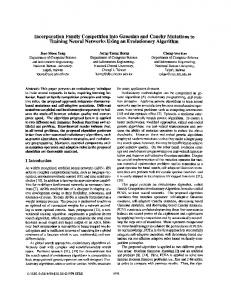
Computationally derived evolutionary designs have shown competitive advantages over human created designs in complexity, creativity and robustness. Our group has demonstrated this in the areas of power system design, low-thrust trajectory optimization, robotic arm deployment path finding, MEMS microgyro calibration, mission planning and scheduling, neural network design, and avionics architecture design. We have also developed a framework for the rapid introduction and parallelization of optimization problems in an evolutionary environment using computer clusters. These techniques offer an alternative approach to system engineering of complex systems by the imposition of design rules (Figure 1). Whereas this has been a successful approach for hardware systems that can rely on physics, mathematics, material science etc. as their foundation, software systems have largely failed to improve in robustness by the imposition of new design rules. The approach of evolutionary computation uses the same principles of variation and selection that have been so successful in the development of natural biological systems.
2. Overview 2.1 Evolutionary Computation Framework The strength of evolutionary computation comes from the ability to utilize existing computer models and simulations that predict the results of multiple input parameters. These types of models are now common elements of computer-aided design (CAD) as well as scientific modeling and forecasting. In evolutionary computational techniques, a population of these models is created and input parameters are varied. The results are evaluated using fitness functions and a percentage of the highest fitness individuals from one generation is promoted to the next generation, while
new models are created through variation (e.g., by mutation or cross-over).
however, that this system goes beyond the traditional optimization approach in that truly novel synthesis and design/selection may be performed by the genetic principles that govern the evolvable system algorithms. The software framework development for this evolvable system effort must be performed by an experienced team of software engineers, computer scientists, electrical engineers, biologists, and physicists in order to provide any hope for a reasonable outcome compared to the high mark targets. Best Structure
Genes Genes Genes
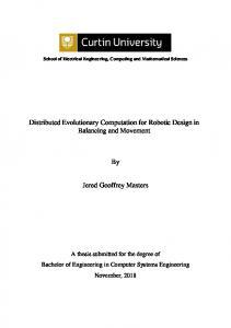
Figure 1. Complexity and Design Rules. As complexity increases from hardware systems to software to nature, the formalism and number of design rules decreases. Current efforts in software engineering are trying to move software systems to higher formalism. Our effort tries to explore the creation of complexity by removing formalism and using a biological evolutionary approach. In order to rapidly adopt new problems into an evolutionary framework we have developed a graphical user interface that enables the parallel operation of genetic algorithms and other optimizers on a cluster computer. This framework enables the tie-in of a variety of different applications and the management of application inputs and outputs. The operation of a parallel genetic algorithm to optimize a variety of tasks has been demonstrated. This evolvable software system also includes a variety of algorithms useful for optimization such as local searches and simulated annealing. We have baptized the framework “Parallel, Evolvable, and Revolutionary Synthesis and Optimization Environment (PERSON)”. The computational architecture of PERSON is based on a package created by D. Levin at Argonne National Lab [1]. The major contribution of PERSON is the scriptable front-end that turned the software into a tool (Figure 2). We have a scripted approach to the integration of applications into PERSON, which enables rapid integration of a variety of different simulations of physical models and a variety of different fitness functions without recompilation of the design environment. This architecture resembles a generalized optimization toolkit that can be applied to a large array of physical system simulation problems that require optimization in a huge search space. Note,
PGAPACK
Fitness Fitness Fitness
MODEL NEMO NEMO Desired Data Simul. Desired Desired Data Data Simul. Data Simul. Data Data Gene Fitness Gene Gene Fitness Fitness
Software Package with Graphical User Interface Input: • Simulation Targets • GA parameters • Platform parameters • Interaction between workstation and supercomputer Output: • Evolution development • Evolution results • Evolution statistics
Figure 2 . PERSON graphical evolutionary computational framework. Models can be introduced with existing tools and simulators and are adapted into a parallel evolutionary environment.
2.2 Evolutionary and Stochastic Algorithms This publication is focused on the application of efficient optimization techniques such as Genetic algorithms (GA) and simulated annealing (SA) to a variety of space science systems. Further discussions of GAs and SAs have been published by this research group with respect to algorithm details and their application to nanoelectronic device designs [2], microelectronic device designs [3], automated circuit designs [4], quantum mechanical basis set selection [5], space craft power system design [6], low-thrust orbit transfers [7], automatic tuning of MEMS devices [8] and neural network evolution [9]. The method of operation is the repeated application of already sophisticated physics based models that predict reality. We would like to mention here that the availability of efficient optimization tools and the ability to explore large parameter spaces also enables the development of more sophisticated physics based models that predict “reality” better. One such concrete example is the development of an advanced model to treat the consequences of arbitrary mechanical strain distortions in semiconductor crystals [10]. This advanced model expands the physical parameter space
dramatically, which could not have been usefully explored without the PERSON framework. GAs and SAs can therefore not only seek better engineering solutions, they can also help refine our physical understanding of problems.
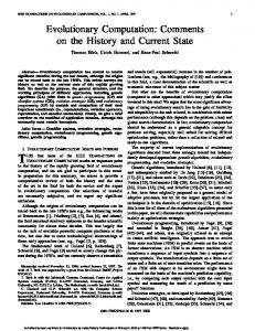
3. Computer Optimized Design We have demonstrated that evolutionary computational techniques can now be used for automatic innovation and design, using the same computer models that are employed to evaluate engineering designs. Four areas, described in this paper, demonstrate human competitive performance as described by Koza et al. [11]. Optimizations and designs using evolutionary techniques result in designs matching or exceeding the performance of those derived from traditional means by human designers. Metrics used for this performance evaluation include design time, robustness and fault-tolerance, cost, and comparison to accepted and flown designs. The areas described in this paper are the automatic design of power systems, robotic arm deployment path planning, the design of low-thrust trajectories and the automatic tuning of MEMS micro-gyroscopes. We expect that future work will lead to further advances in computational engineering and in the development of Computer Optimized Design (COD) (Figure 3.).
Design
+
Computational + Model
Evolutionary Framework
Single design based on expertise of human designer
Predicts and evaluates the outcome (design) of variable sets of input parameters
Competes a population of variable input parameters over many generations
Traditional Design
Computer Aided Design (CAD)
Computer Optimized Design (COD)
Allows only one point of design space to be examined
Allows rapid exploration of alternative designs by human designer
Allows automatic exploration and optimization of designs over huge volumes of design space
Figure 3. Elements of Computer Optimized Design (COD). The use of an evolutionary framework coupled to a computational simulation allows the extension of computer aided design to rapidly and automatically evaluate huge volumes of design space.
4. Results 4.1 Automatic Design of Power Sub-systems Throughout the formulation phase of a JPL flight project, project system engineers engage in an iterative
process of goal definition, mission concept creation and design trade study. They begin with several plausible mission concepts that trade-off various elements in the design. This is done so that project management and their funding agencies can choose between different levels of mass, cost, performance and risk. Once some design choices have been made the process is continuously repeated until the mission architecture is characterized such that its effectiveness in achieving mission objectives can be properly evaluated. Formulating space system concepts that meet payload, trajectory, communication and activity requirements within the mass, cost, performance and risk constraints takes several weeks and relies on experienced teams of domain experts. This may pose some significant problems if project requirements change rapidly or experts are not readily available. Our research in the automated design of spacecraft power subsystems has shown that it is possible to mitigate these problems by automating the creation of power subsystem conceptual designs. Consistent design quality is achieved by using validated performance and resource models to approximate anticipated subsystem performance. Rapid design generation is realized by parallelizing the problem and employing high performance computing. This allows us to evaluate roughly 15,000 unique designs in anywhere from 1 to 18 hours, depending on mission plan complexity and computational power. Our goal was to rapidly generate a diverse set of credible designs so that spacecraft project management and their funding agencies have real choices between different levels of mass, cost, performance and risk. Our approach is was to utilize evolutionary algorithms operating on parameterized space vehicle cost, mass and power subsystem resource and performance models in a parallel processing environment to generate near-optimal designs. The tools used included a JPL power analysis tool called Multi-Mission Power Analysis Tool (MMPAT) and the PERSON evolutionary computing framework. MMPAT in particular was a key component of the system since it models the behavior of a spacecraft’s power sources and energy storage devices as they interact with the spacecraft loads and the environment over a mission timeline. This allowed us to evaluate whether what the system performance and resource consumption would actually be. To achieve diverse solutions we employ a NichedElitist approach. In this method we form artificial subpopulations in the population to emphasize and maintain multiple design solutions. This can be done in either the objective or parameter space. Since we wanted to maintain diversity in the solutions to tradeoff regardless of how similar or different they are we
elected to niche by the objective space. Some of our niches consist of: • Best Performance Design • Least Mass Design • Least Cost Design Best Performance/ Least Mass Design This approach proved superior to other more classical methods we tested. For example while the classical weighted sum approach was intuitive and easy to implement, creating design solutions using this method posed several problems. Since it generates only one design solution at a time, users needed to perform multiple runs in order to obtain a set of possible solutions. More importantly, these solutions may not be evenly distributed, as illustrated in Figure 4a. Furthermore, since evolutionary algorithms are stochastic the method may find an optimal solution only to lose it in later generations. Using the NichedElitist strategy we could generate all of the solutions in one run, distributing them by subpopulation, as shown in Figure 4b. Moreover, since elitism retains the best solutions from both the parent and child populations we were able to keep the best overall design in a particular category.
To evaluate the quality of the generated designs we used mission plans and ancillary data from actual missions then let the system automatically size components. The results were then compared to the actual mission designs to see whether one of the generated designs was close to the actual mission design. For example, one of these tests was an optimization of one of the Mars Exploration Rovers (MER), a NASA/JPL mission of two rovers that landed in January 2004. To setup the analysis we gave the PERSON optimization framework some initial design parameters and a valid range of values. For the MER optimization, we varied the number of cells per string and the number of strings per segment for the six solar array segments, as well as the battery capacity. The PERSON framework chose the initial population based upon a random draw over a uniform distribution for each of the variable power subsystem design parameters before invoking MMPAT. The rover was placed at 14.95 degrees south latitude and given an activity plan that lasted 90 sols (Mars days). This corresponds to the planned length of surface operations of MER-A at the Gusev Crater landing site. The activity plan consisted of applying a 50-watt load for six hours during local daytime and 8 watts the rest of the day. This simulated the load on the rover while it performed its duties during the day, and let it conserve battery power for the heaters at night.
S F
Figure 5. Deep Impact Power System Optimization [12]. Parameter values (such as battery size, solar cell array size, etc.) are plotted by generation for lower cost and mass. Starting values (S) are the as designed power system for the Deep Impact mission. Final values (F) are after 500 generations. Figure 4a and b. Weighted Sum Approach (upper) and Ideal Approach (lower) [12]
Using a population of 200 we ran the analysis for 177 generations using 3 objective functions. This resulted in 35400 designs being evaluated. The optimization took 18 hours using 8 Intel(R) Xeon(TM)
CPU 2.80GHz processors. As expected, this resulted in several credible alternative solutions being generated where each niche optimized their primary objective while compromising the others. An example of an MMPAT subpopulation evolution by generation for a single objective function is shown in Figure 5. Here, starting design parameters (S) (battery size, solar array size, etc.) for the Deep Impact mission is optimize in our evolutionary computing framework for lower mass and cost. For comparison, the first generation is Deep Impact’s actual design parameters. After about 500 generations, the final optimized design (F) showed significant improvements on the cost and mass over the flight design when evaluated at the sub-system level.
overall absolute joint angle movement. The time necessary to calculate a safe deployment path is now reduced from hours to hundreds of milliseconds (on a Macintosh PowerBook 800MHz G4).
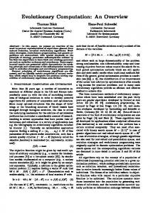
4.2 Rover Arm Path Planning Current and future planetary exploration missions involving landers and/or rover-type vehicles such as Mars Exploration Rover (MER), Mars Science Laboratory (MSL), and subsurface access missions are and will be equipped with robotic arms with four or more joints, each joint having a high degree of freedom (e.g., an angle range of 100 degrees in 1 degree steps). Fast and efficient safe rover movement (e.g., legged rovers and cliff-climbing rovers) and rover arm deployment algorithms, taking rover position and surrounding ground obstacles (e.g., rocks) into account that can be executed with onboard CPU power, will tremendously enhance mission autonomy by cutting down on up-/downlink events, and thus increase the useful lifespan of a mission. This work is capable of increasing science return of future missions and enabling support of intelligent in-situ science experiments to be performed autonomously. The calculation of a collision-free rover arm deployment path is a search in a high-dimensional configuration space. A rover arm consisting of N joints with, e.g., on average 100 angle positions per joint, spans a configuration space of 10(2*N). With N>6, the number of possible configurations lies beyond exhaustive search in a timely manner. To increase the degree of complexity even more, the rover arm deployment requires the generation/calculation of a series of valid configurations, i.e., the safe arm deployment path. We have created three separate software programs using a modified simulated annealing algorithm: 1) calculation of a safe, collision-free rover arm end configuration given a predetermined x-y-z end position of the instrument-carrying joint together with a surface normal at that point; 2) calculation of a safe, collisionfree deployment path from a start rover arm configuration into the pre-calculated end configuration (1); and 3) optimization of safe, collision-free rover arm deployment path with respect to minimizing the
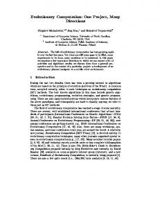
Figure 6. Reachability Map for FIDO Rover: Comparison of digital terrain maps showing reachability of targets with the FIDO robotic arm. Green (light) areas are reachable with arm path solutions. Grey areas are not reachable and red (dark) areas indicate no data available for a solution. Top image is default elbow up reachability derived from the FIDO arm path planning algorithm. This algorithm derives an un-optimized safe path to each target. The bottom image is the same terrain map analyzed with a genetic algorithm to find the safest paths to targets. The larger reachable area of the genetic algorithm i s an indication of the power of the technique in not only providing a greater number of reachable targets, but also in providing the fittest arm path solutions with respect to safety from arm (self and terrain) collisions. We also applied a genetic algorithm [13] to the rover arm path planning problem. Our improved algorithm for the safe rover arm deployment problem uses the following seven-step process: 1. Start with a random initial population 2. Determine arm extent bounding volume to prune the search space 3 . Define fitness function based on obstacle avoidance and goal orientation 4. Perform collision detection and prune population followed by goal orientation 5. Perform mutation with a probabilistic choice of small variation in state or segmented path mutation followed by another fitness evaluation
6.
Promote top 10% of the survivors to the next arm extent bounding volume Repeat steps 2 to 6 until placement point reached. This approach will give an incremental path to the goal position, without having to search through the entire path from start to end position. The simulated annealing-based rover arm path planning algorithm as well as the GA-based algorithm have been successfully tested both onboard the FIDO rover platform and on the FIDO software simulator at JPL (see Figure 6). The optimizer part came up with a novel, shortest (2-step) deployment path from the stowed to the safe rover arm position. We are in the process of deploying both algorithms on the MER rover software simulator and hardware platform, with possible real-world arm deployments during the extended NASA/JPL MER Mars Mission. Details of this work will be documented in a future publication.
genetic algorithm (GA) with non-dominated sorting [7].
4.2 Optimization of Low-Thrust Trajectories Future space missions DAWN and JIMO will use electric propulsion for inter-planetary cruise and orbital operations. The strength of electric propulsion is that in spite of its low thrust levels, the momentum transfer to the spacecraft per kilogram of expelled propellant is ten or twenty times greater than for chemical propulsion. However, the control of lowthrust spacecraft poses a challenging design problem because perturbation forces often dominate the thrust and a significant change of the orbit requires many revolutions. Here we address the problem of designing low-thrust orbit transfers between arbitrary orbits in an inverse-square gravity field by using evolutionary algorithms to drive parameter selection in a Lyapunov feedback control law (the Q-law [14]). The general goal of the design problem is to maneuver a spacecraft with a series of thrust arcs from orbit A to orbit B in the most fuel-efficient and simultaneously time-efficient manner. Since the fuel efficiency and the time efficiency often conflict, the goal of this design problem becomes to determine the Pareto front, which is the envelope in the objective space resulting from the trade-off between the optimal propellant mass and the flight time; each point along the Pareto front corresponds to one particular mission scenario. In order to access the Pareto front with reasonable accuracy and to provide the time history of the state variables and the thrust vector for any chosen point of the Pareto front, we have developed an efficient and efficacious method. A search for the Pareto-optimal trajectories is performed in two stages: 1) optimal thrust angles and thrust-arc locations are determined by the Q-law, and 2) the Q-law is optimized with two evolutionary algorithms: a modified simulated annealing algorithm (SA) and a
Figure 7. Pareto front for an orbit transfer from a slightlyinclined geostationary-transfer orbit to a geostationary orbit.
We applied our method to several types of orbit transfers around the Earth and the asteroid Vesta. Substantial improvements in both final mass and flight time over state-of-the-art are found in the calculation of the Pareto front. For example, for a lowthrust orbit transfer from a slightly-inclined geostationary-transfer orbit to a geostationary orbit we have obtained as much as a 15% propellant savings over the nominal Q-law. Furthermore, the resulting Pareto front contains the optimal trajectories found by other optimization algorithms such as a static/dynamic control algorithm [14] and an orbit averaging technique [15]. Figure 7 shows the substantial improvement in the estimation of the true Pareto front by the optimized Q-law with SA and GA over the nominal Q-law, and the comparable performance of the optimized Q-law to other optimization techniques. Even more promising is that our method builds the entire Pareto front within a few hours of computation time, while other optimization algorithms require a comparable computational effort to acquire a single optimal trajectory. A more detailed description of our method and results is reported elsewhere [7]. Future plans comprise the direct optimization of low-thrust trajectories, i.e., determination of sequence of thrust arcs, both in space and time, and individual duration thereof, independent of human-prescribed control laws such as Q-law.
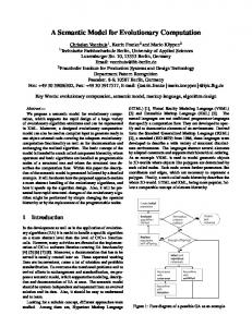
4.4 Automatic Tuning of MEMS MicroGyroscopes The MEMS Micro-Gyro, developed by the MEMS Technology Group at JPL, is subject to an electrostatic fine-tuning procedure, which is necessary due to unavoidable manufacturing inaccuracies. In order to fine-tune the gyro, 4 bias voltages, applied to 8 capacitor plates, have to be determined independently within a range of –60V to 15V. The fine-tuning directly correlates with the accuracy of the gyros in later use. In order to fully automate the time-consuming (on the order of several hours) manual fine-tuning process, we have established a hardware/software test bed to the existing manual gyro-tuning hardware-setup using commercial-off-the-shelf (COTS) components, which includes four programmable power supplies, one offset power supply, and an (electronic) signal analyzer as well as driver and analyzing software. We developed and implemented two algorithms for efficiently determining the bias voltages [8]: 1) a modified simulated annealing algorithm and 2) a dynamic hill-climbing algorithm. Both have been incorporated into the hardware/software test bed. We were subsequently able to successfully fine-tune both MEMS post-gyros and MEMS disk-resonating gyros within one hour for the first time fully automatically to a level of accuracy that is equal to or better than what can be accomplished manually (see Figure 8). One of the key problems solved during the course of this research was to use the “frequency split” between the resonant frequencies along both axes of oscillation as a way to measure the tuning of the gyroscope. Using an open-loop measurement system, the resonant frequencies were determined by scanning through the range of likely frequencies to determine two peaks in the amplitude of vibration. The objective is to reduce the difference in resonant frequencies, also called the “frequency-split”, to zero by changing the bias voltage using SA and GA. The frequency split before tuning can be seen in Figure 9. The resonant frequencies are determined by fitting the data to two Lorentzian curves that model the behavior of the gyro at the frequency of resonance. The best-fit curves are seen in the inset. The fit parameters tell us the position of the peak, and hence the resonant frequency. Using the SA and GA algorithms combined with the curve fitting method we can accurately report the frequency split to a resolution below 0.06Hz, which is considerably better tuning than the resolution determined by a human operator. Automatic MEMS micro-gyro tuning can routinely achieve lower (by 40%) frequency splits in 20% of the time compared to human operators. The final tuned result can be seen in Figure 10.
Figure 9. Fr equency split as a function of Simulated Figure9. Fr 8. equency Frequency split a function of Figure a as function of Simulated Annealing Iterations:split (top)asfor the MEMS post-gyro; Simulated Annealing Iterations: (top) for thepost-gyro; MEMS Annealing Iterations: (top) for the MEMS (bottom) for the MEMS disc-resonating gyro. post-gyro; (bottom) for the disc-resonating MEMS disk-resonating (bottom) for the MEMS gyro. gyro.
Figure 9. The frequency split before tuning. The two Lorentzian curves are shown, as dashed and dotted lines below the solid line indicating the sum of the curves. The inset shows the details of the peak data points.
Figure 10. The frequency split after tuning i s shown, reduced to approximately 0.05Hz. The novel capability of fully automated gyro tuning enables ultra-low mass and ultra-low-power highprecision Inertial Measurement Unit (IMU) systems to calibrate themselves autonomously during ongoing missions, e.g., Mars Ascent Vehicle.
5. Conclusions We have demonstrated that evolutionary computational techniques can be applied to the design and optimization of space systems. Generally, these applications offer better performance (in the range of at least 10%) than traditional techniques and show faster design times. Additionally, changing fitness requirements and redesign, which inevitably occurs in real systems and generally causes great fiscal and schedule disruption, can be accommodated at relatively low cost. Our future work will consider the optimization of multiple sub-systems into full spacecraft optimizations. We are also evolving mission plans and schedules and expect to integrate this work into the codesign of a spacecraft, optimized to the mission plan.
Acknowledgements The work described in this publication was carried out at the Jet Propulsion Laboratory, California Institute of Technology under a contract with the National Aeronautics and Space Administration. The research was supported by the JPL Research and Technology Development Program. Leveraged funding was provided by NASA ESTO-CT, ARDA, and ONR.
References
[1] D. Levin, Argonne National Lab, http://wwwfp.mcs.anl.gov/ccst/research/reports_pre1998/comp_bio/ stalk/pgapack.html [2] Gerhard Klimeck, Carlos H. Salazar-Lazaro, Adrian Stoica, and Tom Cwik, "Genetically Engineered" Nanostructure Devices, in "Materials in Space Science, Technology, and Exploration", MRS Symposium Proceedings, Vol. 551, pg. 149 (1999). [3] Tom Cwik and Gerhard Klimeck, "Integrated Design and Optimization of Microelectronic Devices", Proceedings of 1999 Aerospace Conference, IEEE Volume: 5 , 1999 , Pages: 131 -138. [4] Didier Keymeulen, Gerhard Klimeck, Ricardo Zebulum, Adrian Stoica, and Carlos Salazar-Lazaro, "EHWPack: A Parallel Software/Hardware Environment for Evolvable Hardware", in Whitley Darrell (eds.), Proceedings of the Genetic and Evolutionary Computation Conference (GECCO-2000), July 8-12, 2000, Las Vegas, Nevada USA. San Francisco, CA: Morgan Kaufmann. [5] Gerhard Klimeck, R. Chris Bowen, Timothy B. Boykin, Carlos Salazar-Lazaro, Thomas A. Cwik, and Adrian Stoica, "Si tight-binding parameters from genetic algorithm fitting", Superlattices and Microstructures, Vol. 27, No. 2/3, Mar 2000, pp. 77-88. [6] M. Kordon, G. Klimeck, D. Hanks and H. Hua, "Evoluionary Computing for Spacecraft Power Subsystem Design Search and Optimization," IEEE Aerospace Conference Proceedings, Big Sky, MT., March 2004. [7] S. Lee, P. von Allmen, W. Fink, A. Petropoulos, R. Terrile, “Design and Optimization of Low-thrust Orbit Transfers Using the Q-law and Evolutionary Algorithms” 2005 IEEE Aerospace Conference Proceedings, March 2005. [8] Didier Keymeulen, Wolfgang Fink, Michael Ferguson, Chris Peay, Boris Oks, Richard Terrile and Karl Yee. “Tuning of MEMS devices using Evolutionary Computation and Open-Loop Frequency Response” 2005 IEEE Aerospace Conference Proceeding, March 2005. [9] A.N. Hampton and C. Adami, “Evolution of Robust Developmental Neural Networks”, Proc. of Artificial Life IX, Boston, MA, Sep 12-15, 2004. J. Pollack, M.A. Bedau, P. Husbands, T. Ikegami, and R. Watson, eds., (Boston: MIT Press, 2004) pp 438-443. [10] Timothy B. Boykin, Gerhard Klimeck, R. Chris Bowen, and Fabiano Oyafuso, "Diagonal parameter shifts due to nearest-neighbor displacements in empirical tightbinding theory", Phys. Rev. B 66, 125207 (2002). [11] J.R. Koza, F.H. Bennett III, D. Andre, M.A. Keane “Genetic Programming III: Darwinian Invention and Problem Solving,” 1999, Morgan Kaufmann Publishers. [12] D. Kalyanmoy Multi-Objective Optimization using Evolutionary Algorithms, John Wiley & Sons, Ltd., 2001, p. 2, 172, 239, 173. [13] D.E. Goldberg. Genetic Algorithms in Search, Optimization and Machine Learning. Addison-Wesley, 1989. [14] A.E. Petropoulos, “Simple Control Laws for LowThrust Orbit Transfers,” AAS/AIAA Astrodynamics Specialist Conference, AAS Paper 03-630, 2003. [15] G.J. Wiffen and J.A. Sims, “Application of a Novel Optimal Control Algorithm to Low-Thrust Trajectory Optimization,” AAS/AISS Space Flight Mechanics Meeting, AAS Paper 01-209, 2001.