can provide a wideband wireless access to the Internet by means of the so-called hot-spots. ... communication without the need of an access point (AP), while in.
Experimental Performance of the Handover Procedure in a WiFi Network Roberto Corvaja Andrea Zanella Michele Dossi Adolfo Tontoli Paolo Zennaro University of Padova – Department of Information Engineering via G. Gradenigo 6/B 35131 PADOVA (Italy) e-mail: corvaja, zanella, mic78, tontoli, farstar @dei.unipd.it Tel. +39 049 827 7676 Fax +39 049 827 7699 �
Abstract— An experimental evaluation of the handover performance in a 802.11b (WiFi) network has been obtained in terms of available bandwidth and handover latency. The network consists of two access points connected to a wired LAN and a measurement setup composed by laptop PCs, equipped with WiFi cards, on which a sniffer is used to capture all the packets transmitted on the radio link. Applications considered are streaming and ftp-like applications. The analysis of the handover delay is performed, showing the dependence on the network configuration parameters and results, both at the MAC and UDP/TCP layer are presented, to show how applications can suffer the handover latencies. It will be shown that these latencies can vary significantly for the same configuration of mobile stations and APs and that the primary source of delay is the scan procedure used to discover the new access point. Keywords— Wi-Fi, 802.11b, handover.
1) Discovery 2) Re-authentication A. Discovery Due to mobility, the signal to noise ratio perceived by a mobile terminal might degrade. When it drops below a threshold value, it triggers the station to start searching for another AP, in order to remain connected to the LAN, and initiates the handover procedure. The discovery of a new AP is performed by means of the scanning procedure, which consists in monitoring different channels for beacon signals periodically transmitted by APs. The IEEE 802.11 standard defines two methods for scanning: Passive scanning: the station sets its frequency to a channel and listens to beacons from access points that use that channel. Active scanning: the station issues a so-called Probe Request, on which a Probe Response is expected within a given time frame. Most of the 802.11 systems implement active scanning as it is found to be faster and more efficient. Performing a series of scans on different channels is called a sweep. To conduct a sweep, the station maintains a channel list. There are two kinds of sweep: Full Sweep: all channels in the channel-list are scanned Short Sweep: only a subset of the channel-list is scanned to speed up the roaming process. The subset of the channel-list is dynamically created, and contains channels that have been found to be active during previous scans or where activity is most likely to occur, on the basis of interference criteria. �
I. I NTRODUCTION The wireless LAN standard 802.11b, known also as WiFi, is experiencing a great development [1], [2] and many networks are being installed in campuses, airports, stations, etc. In fact, WiFi can provide a wideband wireless access to the Internet by means of the so-called hot-spots. The IEEE 802.11b specifications define two operating modes, namely ad hoc and infrastructure mode. In the ad hoc mode, two or more stations can recognize each other, establishing a peer-to-peer communication without the need of an access point (AP), while in the infrastructure mode all the mobile stations are associated to an AP that bridges all the traffic. The AP and the associated mobile stations form a Basic Service Set (BSS), which roughly corresponds to a cell in a cellular network environment. The connection of more APs can extend a BSS into an Extended Service Set (ESS) [3]. Generally the WiFi scenario envisages nomadic stations, moving at pedestrian speed. Hence, a major objective is to provide a seamless handover procedure between different BSS [4]–[6]. II. H ANDOVER A Handover occurs when a mobile station moves out from the radio coverage of an AP, entering a new BSS. During the handover, management frames are exchanged between the mobile station and the AP. During this period the mobile station is not able to send or receive any data traffic. The handover procedure refers to the sequence of actions and messages exchanged by access points and a mobile station, resulting in the transfer of a connection from the origin-AP to the destination-AP. The state information transferred typically consists of the client identification and credentials, which allow the mobile terminal to gain network access and accounting information from the new AP. In a 802.11 network, this transfer can be achieved by an Inter Access Point Protocol (IAPP), or by a proprietary protocol. The complete handover process can be divided into two different logical steps:
�
�
�
B. Re-authentication The station attempts to re-authenticate to an AP according to the priority list. The re-authentication process typically involves an authentication and a re-association to a new AP. The reauthentication phase involves the transfer of credentials and other state information from the old AP. IAPP is a protocol which achieves this task, but also proprietary protocols could be used. III. P HYSICAL LAYER PARAMETERS IN THE HANDOVER PROCEDURE
The basic measure that determines a roaming station to switch from one AP to another is the SNR value obtained from the beacon signals. Beacons are issued by all APs at a rate of 10 beacons per second. As soon as the value of the SNR drops below the socalled Cell Search Threshold, the scanning procedure is initiated. The SNR values obtained from each channel are compared with that measured on the active connection: re-authentication and reassociation process is initiated when the difference between the two values exceeds a threshold SNR. The roaming station will remain in the “cell search” state until the SNR has passed the Cell Search Threshold again. �
This work was supported by MIUR within the framework of the “PRIMO” project FIRB RBNE018RFY (http://primo.ismb.it/firb/index.jsp).
Proceedings of WPMC04, 12-15 sept. 2004 Abano Terme (Padova), Italy
A. Handover latency
��
From measurements we have found that the power loss the wireless link obeys a log-distance model of the form
�
along
�������� �� ������������������ �����
(1)
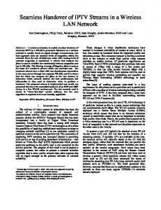
where denotes the distance, expressed in meters, and the attenuation coefficient has been estimated to be . From this model we can estimate the handover time as a function of the main parameters and of the speed of the mobile terminal. Let us consider a model where the mobile terminal (MT) is moving denote the distances from AP1 the from AP1 to AP2 and let separation between the APs.and the distance from AP1 where the cell search procedure is initiated, as depicted in Fig. 1. Then
� !�"
#
��$
�
��%�&
SNR from AP1 SNR from AP2
Fig. 2. Handover delay as a function of the distance between the APs, for the values of sensitivity 1, 2, 3.
SNR th ∆ SNR 3m
d1 MT
AP1
d
AP2 6m
dth
AP2
Fig. 1. Illustration of the physical parameters involved in the handover procedure. AP1
the duration of the handover procedure, considering only the power level, is given by
')(+*
where the distance satisfy
�$ 1
,� $.- # �/%0&
(2) AP2’
from AP1, considered as the origin AP, must
�2-3� $�4 � %�& ���5�6�87= @?�ACB
(3)
Fig. 3. Map of the second floor where the WLAN is installed and location of the APs.
�
The first condition represents the possibility to connect to AP2 and the second represents the actual decision to change AP, on the basis of a better link quality. The value of the Cell Search Threshold for the wireless cards has been estimated equal to 10 dB, 23 dB, and 26 dB, depending on the setting of the parameter sensitivity to 1, 2, and 3, respectively. Assuming a constant noise level of -95 dBm, the handover time increases linearly with after a threshold value, as shown in Fig. 2 for a mobile speed m/s, a transmitted power dBm, and SNR 6 dB. Note that the actual latency is in general dependent also on the scanning strategy used, in particular when the overlapping between the coverage areas of the APs is wide. In this case, in fact, as soon as the cell search begins, the beacon level from the new AP is high enough to satisfy the conditions on the SNR.
D EGF %�&
�
EIH
#J LK
NM� OKP"
�
IV. E XPERIMENTAL S ETUP The 802.11 network consists of two access points (AP) located into an office environment as outlined in the map of Fig. 3. Two scenarios for the location of the APs are considered: in a first scenario the APs are located at the limits of each other coverage, while the second location is chosen to have a sufficient overlapping of the coverage areas, to reduce the handover latency. The position of AP1 is left unchanged, while the position of AP2 is denoted in Fig. 3 by AP2 and AP2’ for the first and the second case considered, respectively. The APs are configured as root, that is, each AP is connected to a wired network and provides wired network.access to the mobile
terminals. We used two APs Compaq WL410 11 Mbps Wi-Fi, 10Base-T and PCMCIA interfaces. The APs are controlled via a web-based network management software (AP Manager) to set their parameters. A proprietary inter-access point communications between APs is implemented. Therefore, no control is applied on the authentication phase. The measurement setup consists of a sniffer (Ethereal) installed on a laptop, able to capture and display packets from any interface, or display packets captured under a number of other capture programs (i.e. tcpdump), save captures to a number of formats, filter packets on many criteria and search for packets using filters and examine packets. all the packets transmitted on the radio channel, so that power levels and delays can be estimated, moving together with another laptop, where the application is running, as depicted in Fig. 4. The mobile terminals are notebook PC, Ethernet
AP1
Hub
R