EXPLOITING MULTIPATH ACTIVITY USING LOW COMPLEXITY EQUALISATION TECHNIQUES FOR HIGHSPEED WIRELESS L A N S Ismail Kaya, Andrew R. Nix & Ralph Benjamin Centre for CommunicationsResearch, University of Bristol, UK e-mail:
[email protected] Abstract: Recent developments have shown that there is considerable interest in wireless high-speed communications. While increasing data rates causes IS1 cancellation problems, it also provides the opportunity to benefit from additional multipath diversity. The use of such diversity is not unique to equalised TDMA systems, indeed it has already been exploited in CDMA systems through the Rake receiver. This paper introduces a ]new Decision Feedback Equaliser (DFE) based on the use of a Channel-Matched-Filter (CMF). The DIT coefficients are directly calculated from the uniform power delay profile of the CMF. The IS1 cancellation accuracy obtained using this method is comparable to the conventional US-Kalman algorithm, however the computation load is significantly reduced. Performance comparisons and implementation benchmarks are given for an indoor 24 Mb/s (HIPERLAN) application.
I. INrRODUCTION The Nyquist criteria states the minimum bandwidth for ISI-free communications. IS1 cancellation becomes a major concern when the channel’s coherence bandwidth becomes less than this Nyquist minimum [l].However, from the early 1970’s the problem of real-time ISI-cancellation has been recognised as a new way to increase data rates by making use of developing signal processing technologies. The resulting equalisation techniques have good spectrum efficiency and can exploit multipath diversity [2][3]. The idea of multipath diversity is a beneficial feature of many advanced communication systems, for example wideband-CDMA where multipath diversity is exploited in a RAKE receiver [4]. The latest complexity figures have shown that the required processing for a TDMA based equaliser is actually much less than that for any advanced CDMA or OFDMA receiver [ 5 ] . On the other hand, most high performance equaliser training algorithms require so many complex operations to be executed within the training time that they are impractical for real-time high data rate communications. This paper introduces a new type of decision feedback equaliser training algorithm which requires substantially fewer real time complex operations to be performed. The method also preserves all the performance benefits of multipath diversity. The equalisation techniques developed to date concentrate on three kinds of criteria; 1) ISI-cancellation based on the peakdistortion criteria, i.e. zero-forcing equalisers [6], 2 ) equaliser training based on the minimum-mean-square error (MMSE) criteria, i.e. MMSE equalisers [ 7 ] [ 8 ]and 3) data recovery in a noisy wideband channel based on maximum posteriori
0-78034320-4/98/$5.00 0 1998 EEE
probability, i.e. maximum likelihood sequence estimation (MLSE) [3] or reduced state MLSE [9]. Since the publication of Bolfire and Park [lo], these criteria have been advanced, but not significantly changed. Because the aggregate noise like effects are not additive, white or Gaussian, the improvement in signal-to-noise ratio (SNR) by using equaliser filters can exceed the matched filter bound (MFB) in a wideband communication channel [8]. A partially matched filter and corresponding IS1 cancellation unit can achieve a performance close to the MFB [ 111. It is well known that tlhe DFE-type equaliser provides better performance than a linear transversal equaliser (LTE). A multipath channel is causal and can be equalised only by a noncausal equaliser, because essentially the equaliser is an inverse model of the channel’s impulse response. The feedback filter (FBF) of the DFE can be made causal and deterministic but the feedforward section of the DFE has to be non-causal [8]. Thus, the number of taps required by the FBF can be limited without any error, however the time window of the feedforward filter (FFF) should be larger than the channel’s tapped-delay-line (TDL) filter model. Residual error is inevitable in a linear equalisation filter with a limited number of FFF taps. Symbol synchronisation can have a critical effect on the equaliser performance and references [ 12][131 suggest symbol synchronisation at the end of the channel profile (not on the more traditional strongest path) in order to obtain the full benefit of the multipath diversity. This means the FFF in the DFE functions to combine multipath diversity. However, this type of synchronisation is not very suitable since it may cause instability in training [ 131, or more often ill conditioned matrix equations in MMSE equalisers [81. Therefore, the proposed equalisation technique uses a CMF to collect all the multipath energy in a single tap in the FFF, thus avoiding any confusion over symbol synchronis,ation. An experimental test bed, using a 16-bit fixed point algorithm and hardware (Analogue Devices ADSP-218 1) was used to investigate the stability and to demonstrate the speed of the algorithm when applied to the HIPERLAN standard. The biterror-rate (BER) and frame-error-rate (FER) performances of the proposed CMF equaliser (CMFE) are provided and compared with those using the RLS, LMS and MMSE-DFE. The performance profiles obtained are also compared with those using delayed-decision feedback sequence estimation, which is a non-linear reduced-state MLSE equalisation technique. Finally, complexity comparisons for the implementation of a 24 Mbits/s HIPERLAN equaliser are given for the techniques considered in the simulations.
1593
VTC ‘98
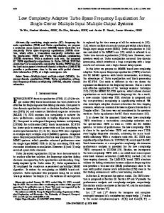
11. CHANNEL MATCHEDFILTEREQUALISER The discrete-time representation of the tapped-delay-line (TDL) filter model for the channel and its matched filter are shown in figure 1 [3][6].
............. a) Channel ....................... ..........................
Lh
Dedector
Figure 2. The DFE Filter.
Figure 2 shows a DFE filter whose output (i.e. an estimation of the k'th symbol) is given by
............. b) CMF Figure 1. Discrete representation of TDL filter model of the multipath channel and its matched filter. The received signal sequence
{vk1
,.o,,.,L,) ~ are the equalizer filter coefficients, where ci ( i = - ~
can be written as,
?k
where { x k } is the transmit signal sequence, hi are TDL filter
is the k'th detected symbol based on the k'th estimated
. easy understanding, we can rewrite equation symbol, i kFor (4) in terms of transmit symbols, using the output equation of the CMF in (3):
coefficients (i=O,1...L), and qk is the k'th additive white Gaussian noise (AWGN) component. The output of the CMF { y k } is given by For a five symbol storage channel (L+1=5 taps in the TDL filter model), if we choose a DFE with 5 FF taps ( L , 4 ) and 4 FB taps (Lh=4),then equation (5) can be written in the form shown in equation (6). i=-L
j=-L
In equation (3) the final IS1 components after the CMF, di r=-L, L , can be calculated as shown in equation (4).
If we apply the peak distortion criteria to equation (6) then the targeted IS1 cancellation window would consist of subsequent interference symbols {xk+,+, x k + 3 , x k + 2 , x k + l } , the cursor or desired symbol { x k }, and previous interference symbols { z k - l , zk-,
L-i
di = ch,*hn+i, i = 0,1,....... L
(4)
n=O
where
the
center
IS1
component
do = h L h L + hE-,hL-l+ .......... h;h,
of
+ hGho,
(4),
is not only the largest component, but also real-valued. This center tap combines all of the multipath energy of the channel. In (4)
0-7803-4320-4/98/$5.000 1998 IEEE
3
zk-3
9
zk-4
1
'
Therefore
the
IS1
symbols
Ink+*, X k + 7 , xk+6, X k + 5 } would be outside O f the FFF Window. Because of the non-causal nature of the FFF, there will be some residual IS1 components, however the FBF covers all the previous symbol's ISI. The zero-forcing ISI cancellation method can also be applied to the targeted window. Thus, a general form to calculate the FFF coefficients of the DFE can be given as in (7), where the FFF coefficients are found independently from the FBF coefficients.
1594
VTC '98
During the theoretical analysis and simulation studies, it was found that equation (7) was not similar to the matrix equation for the MMSE-DFE thiit has been derived from [6][8]. The matrix equation for thfe MMSE-DFE has cross correlation products in the upper-left corner of the matrix equation, which makes the FFF coefficients dependent on the FBF coefficients (assuming no CMF is used in the MMSE-DFE case). In particular, this prevents the partitioning of the matrix equation and requires a (Lf+l+L,,)x(Lf+l +Lb) matrix inversion. Therefore, the CMFE significantly reduces the required number of operations during the matrix inversion. If the CMF is present in the receiver then the CMFE and the MMSE-DFE share similar matrix equations. as shown in (7) and (8), and thus have similar complexity. Given the similarities, we can observe that equations (7) and (8) provide DFE coefficients which are close to the optimum boundary. 111. PERFORMANCE COMPARISONS OF THE CMFE
L(-l-j
+
I
"
Forj=O,....Lf-l, z d , j - i ~ i - L fzdt**ci-,, = 0 i=O
(7.a)
i=l L . -I
d, f - ici-L,= 1
For j=Lj (center tap),
(7.b)
i=O
where dj=O if i>L. The FBF coefficients can be simply calculated by equation (8), where the FBF coefficients are totally dependent on the FFF coefficients.
where the number of FBF taps ( L b ) would be one less than the channel tap number (L), Lh=L, because there are no IS1 components remaining outside the FBF window belonging to the previous symbols as shown in equation (6). Equation (7) is a ( L +~I ) x ( L +~I ) Teoplitz matrix equation
In this section BER arid FER results are given for various equaliser algorithms operating in a HIPERLAN type 1 scenario [15]. The HIPERLAN system transmits at 24Mb/s and the frame structure includes 450 training symbols followed by up to 47 data packets, each containing 496 information symbols. In the simulations, the data is sent through a wideband channel of varying delay spread The channel taps are each subject to Rayleigh fading around their mean value. The results were obtained by averaging over 500 transmissions each through a unique channel. The average statistics of these channel had a fixed RMS delay spread in the region of 7511s. The LMS algorithms (LMS-LTE and LMS-DFE) were trained over 350 symbol periods with a step function of 0.045. The RLS algorithm was trained over 64 symbols with a forgetting factor of 0.95. The IMMSE-DFE and MMSE-LTE were simulated according to references [6][8]. To perform channel estimation and synchronization, a 63 symbol Pseudo-Noise (PN) sequence was used. A five tap channel profile (with average tap coefficients of 0.227, 0.460, 0.688, 0.460, 0.227) was used as suggested by Proakis [6]. For the LinearTransversal-Equaliser (LTE) 13 filter taps were used, and for the DFE filter 9 FFF tap!; and 4 FBF taps were assumed.
1 E-1
3
1E-2
MMF&ITC
8 3
4
LMb ITF
1E-3
8
I5
and can be solved simply using the Levinson-Durbin algorithm [14]. However our simulation studies have shown that the Gauss-Elimination algorithm provides more accurate calculation. The DFE then performs better and the GaussElimination algorithm can be simplified for the Teoplitz matrix inversion. The solution of equation (8) does not require matrix inversion.
0-7803-4320-4/98/55.00 0 1998 IEEE
1E-4
1E-5 1E-6
I
I
0
CMF-DFE
I
0
20
, 30
SNR in dB
Figure 3 BER performances of equalisers (a 13 taps LTE, or 9 FFF and 4 FBF taps DFE is used for simulations).
1595
VTC '98
“‘1 3E-3
1E-3
+
1
\\ KLb-”rE
\
1
’ I
CMF-DFE
I
’
0
,
I
10
20
MMSE-DFE
I
I
30
SNR in d 6
Figure 4. FER Performances of equalisers. Figure 3 shows that the CMF-DFE produces a better BER performance than the other training methods. The RLS-DFE performance is very close to that of CMF-DFE (within 1 dB). The MMSE-DFE is approximately 5 dB worse in SNR performance than the IUS-DFE and CMF-DFE (considered BER value is equal to 0.001). Finally, from figure 3 it can be seen that the DFE significantly outperforms the LTE equaliser filter for all training algorithms. The FER performance of the equalisation algorithms are shown in figure 4. A frame-error was said to occur if any bit error was detected in a data packet (496 symbols). The FER performance is generally similar to the BER results, with the LMS-DFE performing slightly better than expected. 3E-2
I
1E-2
:
2 3E-3
To generate a better understanding of the ISI-cancellation performance, figures 5 and 6 show the BER and FER results for various values of normalized RMS delay spread(NRMS) [15]. For these results, the channel gain was kept constant in order to maintain an SNR of 21 dB for each value of RMS delay spread. The CMF-DFE has the best BER and FER performance in all IS1 regions. When the channel has low IS1 (i.e., NRMS=O. 1) then all the equalisation methods give similar results. However, for IS1 limited conditions, (i.e. NRMS > 0.9), then the multipath nature of the channel plays an important role and the equalisation methods behave differently. The RLSDFE and CMF-DFE are very successful at canceling the IS1 and exploiting the multipath diversity. However the MMSEDFE suffers at high values of ISI, and this is believed to be caused by imperfect symbol synchronization. We have concentrated on.the upper boundary of the noise limited region (SNR=21 dB). It is interesting to note that the behavior of the various equalisation techniques are surprisingly different in this high SNR region.
Iv. IMPLEMENTATION OF THE CMFE AND RESULTS The CMF-DFE has been implemented using the Analog Devices ADSP218116 processor (16 bits, 33 MIPS). A 32 symbol PN sequence is used for frame synchronization and channel estimation.
I
-
w
B p! 1E-3
2c
7
3E-4 -
to DSP in the lab. test bed )
k
CMF-D
t
3E-5 1E-5’
FYDR
SNR=21 dB
Y
’
” ”
0 01
I
,
I
, , , , I
I
I
0 03 01 03 RMS delay spread, normalised to symbol period
I
1
____......__________...I.
Figure 5. BER performances against RMS delay spread. 2E-1
Samp 1
I
IS1 Cancellation
-
1E-1 :
6 5E-2 4
+
ZE-Z
$
1E-2 -
U
8
~
5E-3
1
SNR=21 dB
c ~
Equalised Datu, QAM modulated
CMF-D 2E-3’ ’ ’ ’
”
0 01
I
0 03 01 03 RMS delay spread, normalisedto symbol period
1
Figure 6. FER performances against RMS delay spread
0-78034320-4/98/$5.00 0 1998 IEEE
Figure 7. Bufferless CMF equaliser implementation
,
The block diagram for our real time implementation of the proposed CMFE (based on the HIPERLAN application), is
1596
VTC ‘98
given in figure 7. In the laboratory test bed, a DSP correlator has been used for synchronization and the DEE was implemented using 9 taps (5 FFF, 4 FBF). At the beginning of each packet, the DSP requires 300 microseconds to achieve synchronization. However, if a hardware correlator is used as shown in figure 7, the synchronization process would take less than 4 microseconds. The equaliser training uses a reduced complexity Gauss-Elimination method and requires 12.4 microseconds of DSP time. Finally, another critical part is the coefficient orientation and this requires less than 1.5 microseconds before starting the equalisation. The coefficient orientation is considered after loading the coefficients into the DFE filter. The process is implemented using an adaptation algorithm to decide the magnitude of the data values in the feedback-filter. This is a necessary step for all direct coefficient calculation methods, since it is beneficial to use 16-bit resolution during coefficient calculation without, regard for the incoming data level. This helps to speed up the training process and also obtains the best possible set of coefficients.
DSP. The MMSE-DFE can also be used for HIPERLAN type applications using a 16 lit, 100 MIPS, processor. However, as illustrated by the results in this paper, the implementation requires very accurate symbol synchronization to fully exploit the multipath diversity effects. Finally, the LMS-DFI! may not always be suitable for HIPERLAN applications since it requires an 8 bit, 800 MIPS, processor and suffers from residual error floors in high IS1 limited environments. ACKNOWLEDGMENTS
The authors would like to thank to Joe McGeehan, Dave Bull, Ross Wilkinson, Yusuf 13altaci and David Jennings.
REFERENCES H. Nyquist, “Certain Topics in Telegraph Transmission Theory”, AIEE Truns., vol. 47, pp. 617-644,1928 H. Harashima, H. Milyakawa, “Matched-Transmission Technique for Channels with Inter-Symbol-Interference”, IEEE Trans. on Commun., Vol. COM-20, pp.774-’780, August 1972. G.D. Foumey, “Maxinmm Likelihood Sequence estimation of Digital Sequences in the Presence of the Intersymbol Interference”, IEEE Truns. on Inform. Theory, Vol. IT-18, pp. 363-378, May 1972. F. Adachi, “Multi-rate Wideband DS-CDMA: promising radio access technology for wireless multimedia communications”, Proceedings of the IRCTR Colloquium on Indoor C., pp.17-25, Delft, Netherlands, 24 Oct. 1997 R. Hasholzner, C. Drewes, J. S. Hammerschmidt, Multiple Access and Equalisation Issues for 156 Mb/s ATM Radio in the Local loop”, ACTS Mobile Communicatiasns, Summit’97, pp.647-652, Oct. 7-10 1997, Aalborg, Denmark. J.G. Proakis, “Digital Communications”, McGraw-Hill, Third Ed. 1995. N. AI-Dhahir, J.M. Cioffi, “MMSE Decision-Feedback Equalisers: Finite Lenght Results”, IEEE Trans. on Irtformution Theory, Vo1.41, No.4, pp. 961-975, July 1995. J.M. Cioffi, G.P. Dudevoir, V. Eyuploglu, D. Fomey, “MMSE Decision-Feedback Equalisers and Coding - Part 1:Equalisation Results”, IEEE Truns. on C~mmunic~tion.~, Vol. 43, No. 10, pp.25822594, October 1995. A. Duel-Hallen, C. Heegard, “Delayed Decision Feedback Sequence Estimation” IEEE Trans. on Communication, vo1.37, No.5, pp.428436, May 1989. C.A. Belfiore, J.H. Park, “Decision Feedback Equalisation”, Proc. of the IEEE, Vo1.67, No.8, pp.1143-1156, Aug. 1979. S. Ariyavisitakul, L.J. Greenstain, “Reduced-Complexity Equalisation Techniques for Broadband Wireless Channels”, IEEE Journul on Selected Areus in Communications, Vo1.15, No.1, pp.5-15, January 1997. S.U.H. Qureshi, “Adjustment of the Position of Reference Tap of an Adaptive Equaliser”, IEEE Trans. on Communications, Coincise Papers, pp.1046-1052, September 1973 I. Kaya, R. Benjamin, A.R. Nix, “Two-way Basestation Equalisation for Mobile Multi-Media Communication”, (MoMuC-2) 2. Intemational wokshop on Mobile M ulti-Media Communication, Bristol, 23-24 April 1995. M.H. Hayes, “Statistical Digital Signal Processing and Modelling”, John Wiley and Sons, 1996 A.R.Nix, G. Athanasiadou, J.P. McGeehan, “Predicted HIPERLAN Covarageand Outage F’erformanceat 5.2 and 17 GHz Using Indoor 3-D Ray Tracing Techniques”, Kluwer Ac. Publishing, Special issue on HIPERLAN, vo1.2, no 4, pp. 365-388, 1996. Radio Equipment and Systems (RES), “High PErformance Radio Local Area Network (HIPLERLAN)”, Functional Specifications, ETSI, 1995
Based on the above analysis, equaliser synchronization and training would be complete within the reserved 18.2 microseconds available in HIPERLAN (i.e. the time allotted to the 450 bit training sequence) [15][16].
Figure 8: Required Processing Speed for Equaliser Training in a HIPERLAN Frame (Training time = 18.2 microseconds) Finally, figure 8 shows a table of the final algorithm complexities for HIPERLAN training. From this graph it can be seen that the CMF-DFE is easily the least complex of the methods considered in this paper. V. CONCLUSIONS
This paper has presented a simple CMF-DFE architecture and associated training algorithm for high speed wireless data applications. The BER and FER results show that the method outperforms the RLS approach, despite its complexity being two orders of magnitude lower. Generally, the RLS-DFE is considered too complex to implement for HIPERLAN applications. Practical DSP results have shown that the CMF-DFE provides optimum performance and can achieve real-time HIPERLAN equaliser co-efficient calculation using a simple 16 bit, 33 MIP,
0-78034320-4/98/$5.000 1998 IEEE
1597
VTC ’98