PAPER
www.rsc.org/loc | Lab on a Chip
Fabrication and characterization of high-temperature microreactors with thin film heater and sensor patterns in silicon nitride tubes R. M. Tiggelaar,*a J. W. Berenschot,a J. H. de Boer,a R. G. P. Sanders,a J. G. E. Gardeniers,b R. E. Oosterbroek,b A. van den Bergb and M. C. Elwenspoeka Received 24th September 2004, Accepted 17th December 2004 First published as an Advance Article on the web 13th January 2005 DOI: 10.1039/b414857f In this paper the fabrication and electrical characterization of a silicon microreactor for hightemperature catalytic gas phase reactions, like Rh-catalyzed catalytic partial oxidation of methane into synthesis gas, is presented. The microreactor, realized with micromachining technologies, contains silicon nitride tubes that are suspended in a flow channel. These tubes contain metal thin films that heat the gas mixture in the channel and sense its temperature. The metal patterns are defined by using the channel geometry as a shadow mask. Furthermore, a new method to obtain Pt thin films with good adhesive properties, also at elevated temperatures, without adhesion metal is implemented in the fabrication process. Based on different experiments, it is concluded that the electrical behaviour at high temperatures of Pt thin films without adhesion layer is better than that of Pt/Ta films. Furthermore, it is found that the temperature coefficient of resistance (TCR) and the resistivity of the thin films are stable for up to tens of hours when the temperature-range during operation of the microreactor is below the so-called ‘burn-in’ temperature. Experiments showed that the presented suspended-tube microreactors with heaters and temperature sensors of Pt thin films can be operated safely and in a stable way at temperatures up to 700 uC for over 20 h. This type of microreactor solves the electrical breakdown problem that was previously reported by us in flat-membrane microreactors that were operated at temperatures above 600 uC.
Introduction Silicon microreactors offer the possibility to control and study potentially dangerous and/or fast reactions such as exothermic reactions or reactions with flammable, explosive, toxic or hazardous chemicals under relatively safe conditions. This is possible due to their small characteristic dimensions, the high thermal conductivity of silicon and high level of integration of control functionality.1–3 In silicon microsystems utilized for high-temperature applications usually metal thin film heater structures are used to (pre-)heat a gas mixture and to induce a chemical reaction, whereas metal thin film temperature sensor arrays and flow sensor patterns are used to control the reaction.3–8 The advantages of silicon were used in previous studies to develop microreactors for controlling and studying highly endothermic4 and exothermic1,3 reactions. Both types of microreactors reported before were ‘flat-membrane’ reactors: they consisted of a flow channel etched in a silicon substrate, covered on one side with an aluminum or Pyrex glass plate and on the other side with a thin sheet of material—to be called ‘membrane’ in the remainder of the paper (not to be confused with permeable membranes normally used in chemical engineering) with heaters on the outside and a catalyst layer on the inside (i.e. the channel side). The membrane in these microreactors was made of a layer of silicon nitride in order to obtain fast time-constants for heating up of the gas and the reactors were used for research on the kinetics of ammonia *
[email protected]
326 | Lab Chip, 2005, 5, 326–336
oxidation or methanol dehydrogenation.1,3,4 Due to the excellent thermal properties of the membrane, the reactions could be investigated over a wide temperature range, under relatively mild conditions and in a safe way. These microreactors were developed specifically for analytical purposes, to explore novel chemistry and to screen catalysts and reaction conditions. A drawback of these flat-membrane microreactors is that they cannot be used at temperatures above ca. 550 uC: at these temperatures the membrane of silicon nitride ruptures due to high thermally induced stress.3,4 In previous papers9–11 we have described the modelling and fabrication of silicon microreactors to be used for kinetic studies of rhodiumcatalyzed partial oxidation of methane to synthesis gas, the design of which was based on the mentioned flat-membrane concept. It was found that a design with a membrane composed of 850 nm boron-doped monocrystalline silicon, p++-Si, and 150–200 nm of either low-stress silicon-rich silicon nitride (SiRN) or stoichiometric silicon nitride (Si3N4) results in time constants of 1 ms for heating up and cooling down, which enables the required fast control of the exothermic reaction. Thermo-mechanical analyses and experiments without gas reactions demonstrated that microreactors with membranes of 850 nm p++-Si and 200 nm Si3N4 have an efficient thermal behaviour and excellent (thermo) mechanical behaviour up to 700 uC. However, it was observed that when the temperature at the catalyst surface locally exceeded 600–625 uC, the membranes ruptured at positions where catalyst patches were present. This failure was very likely caused by electrical breakdown of the This journal is ß The Royal Society of Chemistry 2005
silicon nitride, which in its turn was caused by a large temperature rise of the catalyst surface because of starting up of the exothermic CPO reaction. Due to this electrical breakdown, a short-circuit between the thin film heater and the underlying p++-Si was created. For a short moment, a large current flowed through the short-circuited path, resulting in a hot spot at the position where breakdown occurred. The consequence of this hot spot was that a small hole was burnt through the p++-Si layer. This perforation resulted in membrane fracture due to intrinsic tensile stress present in the p++-Si and the silicon nitride. As a consequence the composite flat membrane microreactors could be used up to temperatures of the catalyst of 600 uC.9 In this paper the fabrication and electrical characterization of a silicon microreactor is discussed that can handle temperatures well above 600 uC. In this microreactor, electrical breakdown of the layer of silicon nitride is not possible, simply because a layer sandwich of metal–dielectricum–p++-Si is not present in areas of the flow channel where the temperature becomes higher than 500 uC. Although this microreactor was developed for research on kinetic parameters of high-temperature reactions, it may also be used for small-scale, on-demand production of synthesis gas or as a hydrogen source for micro fuel cells.
Design of a microreactor with heaters in silicon nitride tubes with corrugated zones A way to prevent electrical breakdown of the dielectric material between the thin film heaters and the p++-Si part of the membrane is to omit the silicon part. However, as mentioned above, microreactors with a 1 mm thick flat membrane of SiRN showed large thermally induced stresses during operation at temperatures above 550 uC which resulted in buckling of the membrane and eventually rupture.3 In solid-state devices, like pressure sensors, mechanical decoupling zones are frequently used to reduce such stresses or stresses due to packaging and encapsulation that may affect the characteristics of the device. In Fig. 1 several different mechanical decoupling zones are shown. Due to a significant reduction in radial stresses, membranes with corrugated decoupling zones are capable of compensating for much more pressure difference and induced stress than membranes with flat decoupling zones.12,13 The amount of induced stress that membranes with corrugations can withstand depends on the geometry of the corrugated zones like the number of corrugations, its thickness, its depth and the crosssectional shape, the thickness of the membrane and the used materials. Frequently used cross-sectional shapes of corrugated zones are rectangular, circular, trapezoid, sinusoidal, V-shaped and U-shaped profiles.12–15 Modelling of corrugated decoupling zones showed that the amount of corrugations and the stiffness of the decoupled membrane are correlated negatively: the more corrugations, the less the stiffness of the decoupling structure.12,13 A severe problem that might arise when corrugated decoupling zones are integrated in micromachined devices is the application of electrical wires in the device, e.g. for electrical read out of strain gauges on deflecting membranes. This journal is ß The Royal Society of Chemistry 2005
Fig. 1 Several configurations of mechanical decoupling zones for stress reduction in membrane structures.
Due to the corrugated zones, standard techniques like lithography and lift-off cannot be applied. Methods are known that provide planarization after realization of corrugated zones,16,17 however the application of these methods is not very general and non-trivial. We have developed a microreactor based on a SiRNmembrane which includes corrugated zones, that can withstand high thermally induced stresses. In Fig. 2 a schematic cross-sectional view of the flow channel of such a microreactor is given. As can be seen, the corrugated zones are directed outof-plane, in contrast to conventionally corrugated zones that are in-plane with the membrane (Fig. 1). The heater is used to heat up gases and catalyst patches in the flow channel to temperatures above 500 uC. Due to Joule dissipation of electrical power in the thin film heating filament,
Fig. 2 Schematic cross-sectional view of flow channel of microreactor that contains thin film heaters located in SiRN-tubes that can withstand high thermally induced stresses due to inclusion of corrugated zones.
Lab Chip, 2005, 5, 326–336 | 327
the heater and membrane expand a little. The corrugated zones are used to decouple the expansion of the SiRN-membrane and the thin film heater. In the design of the microreactor, the SiRN-tubes contain one corrugation at each side (Fig. 2). One corrugation in the tube is enough to obtain mechanically stable silicon nitride structures at high temperatures, whereas this low amount of corrugations also guarantees stiff and robust structures, e.g. the tubes and thin film patterns are not damaged/cracked/broken by vibrations or shocks.
Fabrication of microreactors with thin film heaters and sensors in silicon nitride tubes with corrugated zones The description of the fabrication of the microreactor is divided into 4 sections: realization of SiRN-tubes, manufacturing of the flow channel, deposition of thin film structures in the SiRN-tubes and finalization aspects, like deposition of patches of catalyst material in the flow channel, bonding and dicing. Silicon nitride tubes Fig. 3 shows the fabrication process up to and including the formation of the SiRN-tubes with integrated corrugations. The process sequence runs as follows: a layer of 500 nm SiO2 is grown on a low doped p-type double-side polished (110) silicon wafer with a thickness of 380 mm and a diameter of 100 mm. The SiO2 layer is grown using oxidation in steam at 1150 uC. With standard lithography, a pattern of heater and temperature structures, contact wires and contact pads is defined (wire widths ranging from 20 mm to 1 mm—Fig. 3(a)). Etching in BHF (buffered hydrofluoric acid) is applied to remove the exposed SiO2; during this etch-step SiO2 on the backside of the wafer is protected by resist. After removal of the resist (in 65 wt.% HNO3), a SF6-plasma etching step is used to transfer the wire pattern into the silicon (the SiO2 layer is used as an etch mask). In Fig. 3(b) the result of these steps are shown in a 3D-scheme. The depth of the etched trenches is y60 mm. It is noted that the complete pattern of heaters and temperature sensors, contact wires and contact pads is deepened with respect to the topside of the silicon wafer. Next, a second layer of SiO2 is created using wet oxidation at 900 uC (35 min). The measured thickness of the SiO2 layer at the bottom of the trenches is larger than the additional SiO2 layer on top of the wafer: 100 nm and 50 nm, respectively. Thus, after this SiO2 growth step, a significantly thicker SiO2 film is present on top of the wafer than at the bottom of the trenches: y500 nm and 100 nm, respectively (after etching of the trenches the remaining SiO2 film on the topside was y450 nm–Fig. 3(c)). With a directional CHF3-plasma etch step, the SiO2 coating at bottom of the trenches is removed, whereas SiO2 remains on the topside of the wafer (due to its large thickness) and on the sidewalls of the trenches (due to the high directionality of etching—Fig. 3(d)). After directional removal of the SiO2 from the bottom of the trenches, isotropic etching of silicon with an SF6-plasma is performed (Fig. 3(e)). The radius of the tubes thus formed in silicon was 4.5–5 mm after 10 min of etching. 328 | Lab Chip, 2005, 5, 326–336
Fig. 3 Fabrication process of SiRN-tubes that can withstand high thermally induced stresses due to inclusion of corrugated zones (a)–(f) (SiRN is low-stress silicon rich silicon nitride); SEM-picture (topview) of SiRN-tubes (g). Details of fabrication steps are given in the text.
Subsequently, the SiO2 film was removed using 50% HF. Finally, a 1 mm layer of SiRN was deposited by a Low Pressure Chemical Vapour Deposition (LPCVD) process using SiH2Cl2 and NH3, resulting in the formation of SiRN-tubes embedded This journal is ß The Royal Society of Chemistry 2005
in silicon (Fig. 3(f)). SiRN is preferred above stoichiometric silicon nitride (Si3N4) because of the relatively high intrinsic tensile stress in Si3N4-films.18 The technology developed to realize the SiRN-tubes is a modification of the ‘Buried Structure Technology’ (BST).19,20 We adapted the method to obtain corrugated membranes and, as will be seen below, patterned metal structures by using the trench structures as a built-in self-aligned shadow mask. As shown in Fig. 3, with only one lithographic step and a mask containing heater and temperature structures, contact wires and contact pads, the complete topside structure of the microreactor is defined. Subsequently this structure is transferred into the silicon by means of the Bosch-process (Fig. 3(d)) and a release-step (Fig. 3(e)). In the microreactor, structures with widths of 20 mm (temperature sensors), 50 mm (heaters), 50–500 mm (contact wires) and 1 mm (contactpads) were implemented, and these structures were etched to a depth of y60 mm below the wafer surface. A recently developed etching procedure, called the ‘TWIN-process’, can be used to obtain much deeper trenches (up to several hundreds of microns) for a large variety in opening widths (microns to millimeters) without affecting: (i) the uniformity in etched depth of structures with different opening widths, or (ii) the crosssectional shape of the etched trenches.21,22 Furthermore, when this process is employed, the steps shown in Fig. 3(b)–(e) can be combined in one step, which simplifies the fabrication and significantly reduces the fabrication time. Flow channel In Fig. 4 the fabrication of the flow channel of the microreactor is shown, including the formation of suspended SiRNtubes (with integrated corrugations) in which thin film heaters are to be deposited. After deposition of a SiRN layer (Fig. 3(f)), the SiRN layer is completely removed from the backside of the wafer using a CHF3-O2 plasma. Subsequently, the flow channel (500 mm wide, 3 cm long) is defined on the backside of the wafer using standard lithography (Fig. 4(a)). The photoresist layer, which was annealed at 150 uC for 35 min, served as a mask during Reactive Ion Etching (RIE) of a 325–330 mm deep flow channel in silicon. In Fig. 4(b) a topview of the flow channel is given, whereas in Fig. 4(c) a backside view is presented. As can be seen in Fig. 4(c), the SiRN-tubes are revealed during etching of the flow channel in the backside of the wafer. Due to selectivity of the used SF6 gas, silicon is etched while SiRN is not attacked. The shape of the suspended SiRN-tubes is identical to the heaters used in previously mentioned flatmembrane microreactors.9,10 However, other shapes can be easily made, as will be seen below. It is noted here that after creation of the flow channel only the SiRN-tubes in the flow channel become suspended. Underneath all other SiRN-tubes, like below the contact-wires and contact pads, silicon is not removed. After revealing of the SiRN-tubes in the flow channel, either isotropic Si-etching or anisotropic Si-etching can be used to etch a deeper flow channel. In Fig. 4(d)–(e) both steps are shown. By applying one of the etching methods (or a combination of them), the dimensions of the Si-parts labelled ‘A’ This journal is ß The Royal Society of Chemistry 2005
Fig. 4 Fabrication process of the flow channel of a microreactor with SiRN-tubes that can withstand high thermally induced stresses. Details of fabrication steps are given in the text.
and ‘B’ in Fig. 4(f) can be tuned. The size of A and B determines the length of the SiRN corrugated zone labelled ‘C’ in Fig. 4(f)). The length of this zone determines the amount of thermally induced stress that the suspended tubes can withstand. Furthermore, the thermal efficiency (defined as the Lab Chip, 2005, 5, 326–336 | 329
percentage of input energy to the heating filaments that is transferred to the gas mixture) is influenced by the length of the SiRN corrugated zones. In Fig. 5 SEM pictures of suspended SiRN-tubes in the flow channel of the microreactor are shown.
Metal thin film deposition in SiRN-tubes Fig. 6 is a schematic view of the microreactor after the deposition of metal thin films. As can be seen, metal is deposited on the top surface of the wafer and on the bottom of the SiRN-tubes. The metal thin film in suspended SiRN-tubes form heaters and temperature sensors, whereas the thin film at the bottom of all other SiRN-tubes (embedded in silicon) form contact wires and contact pads. When for deposition of metal thin films a highly directional deposition method is used, like e-beam evaporation, the sidewalls of the SiRN-tubes function as a built-in shadow mask during deposition: metal is only deposited on the top surface of the wafer and the bottoms of the SiRN-tubes and not at the sidewalls of the trenches. Furthermore, the circular decoupling zones at the bottom of the trenches guarantee the impossiblity of electrical contacts between metal deposited on the bottoms of the tubes and sidewalls of the trenches, if some metal would be deposited on these sidewalls. Finalization After the fabrication steps described above, the microreactor is finished by performing the following steps: first, 30 nm of silicon dioxide is formed on the silicon in the flow channel using a LOCOS (local oxidation of silicon) process in steam at 900 uC for 1 min to ensure no direct contact between Rh and silicon, in order to avoid the formation of Rh-silicides.9,23 Then, sputter deposition of catalyst patches of 20 nm thick Rh
Fig. 5 SEM-pictures of suspended SiRN-tubes in the flow channel of a microreactor: (a) global overview, (b),(c) zoom-in on suspended SiRN-tubes, (d) cross-section along line BB’ indicated in (b).
330 | Lab Chip, 2005, 5, 326–336
Fig. 6 Schematic view of deposition of a metal thin film in the SiRNtubes of the microreactor. The metal thin film in suspended SiRN-tubes form heaters and temperature sensors, the thin film in embedded SiRNtubes form contact wires and contact pads.
This journal is ß The Royal Society of Chemistry 2005
underneath the suspended SiRN-tubes is performed through a 3D-self aligning shadow mask. Details of this shadow mask and its use are discussed elsewhere.9,24,25 After anodic bonding of a Pyrex baseplate with powderblasted inlet and outlet holes to the backside of the silicon wafer, the silicon-Pyrex stack is diced, resulting in microreactors of 3.0 6 4.5 cm.26,27
Characterization of microreactors with thin film heaters and sensors in silicon nitride tubes with corrugated zones In this section experimental results are discussed that are obtained during characterization of microreactors with suspended, corrugated SiRN-tubes containing thin film heaters. Sputter deposition of metal thin film in SiRN-tubes with corrugated zones It was observed that physical degradation of Pt thin films used as heaters, temperature sensors or catalyst, is mainly caused by reactions and diffusion processes related to the adhesion layer, usually Cr, Ti or Ta.28–34 This degradation leads to drift in electrical parameters of the thin film, for example in its resistivity and temperature coefficient of resistance. Therefore, the applicability of using Pt thin films without adhesion material—referred to as ‘pure Pt’ in the following—in the suspended-tube microreactor is investigated. In this paper only the electrical behaviour of Pt thin films and Pt/Ta thin films at high temperatures is considered. Other high-temperature aspects of these thin films are discussed elsewhere.35 Generally, with evaporation processes it is very difficult to obtain pure Pt thin films with good adhesive properties. In the literature, only one method is mentioned to obtain welladhered pure Pt films in micromachined devices: this method is based on sputter deposition in an Ar/O2 atmosphere.36,37 Therefore we used sputter deposition to obtain well-adhered Pt films in the SiRN-tubes of the microreactor. Since sputter processes have a significantly higher step coverage than evaporation, the process sequence mentioned earlier had to be modified as follows: After etching of the flow channel, the SiRN at the topside of the wafer and at the bottom of the SiRN-tubes is exposed to an SF6–O2 plasma for 100–105 s (6:1 gas-ratio, pressure 40 mTorr, power 60 W) to increase surface roughness (see below). Subsequently, 200 nm Pt is sputter deposited. Due to the relatively high step coverage of sputtering, a (very) thin metal film is deposited on the vertical sidewalls of the SiRN-tubes as well as in the corrugated zones; after sputtering, short circuits were detected between heaters and temperature sensors. These short-circuits can, however, be removed as follows: After sputtering, the platinum film is exposed to an O2-plasma (60 s, pressure 10 mTorr, power 60 W). Since the pressure is low, this plasma is highly directional. Therefore, only the platinum on the surface of the wafer and at the bottom of the SiRN-tubes is passivated by a thin oxide film; the platinum on the sidewalls of the trenches and in the corrugated zones is not passivated. Inspections revealed that passivated Pt looks yellow-brown, whereas unexposed Pt preserves the gray colour of as-deposited Pt. According to Kim et al. the thickness of the oxide on top of the This journal is ß The Royal Society of Chemistry 2005
Pt film is 10–12 nm.38 Then, non-passivated Pt is etched away in a mixture of H2O, HCl and HNO3 (ratio: 8:7:1, temperature etchant 90 ¡ 1 uC, etch time 2 min), leaving well-defined pure Pt films at the bottom of the SiRN-tubes. In this ‘aqua regia’ the etch rate of O2-passivated Pt films is highly reduced,38 whereas unexposed Pt dissolves fast.39 In our case, thickness measurements showed that no etching of exposed Pt occurred and that unexposed Pt etched with more than 100 nm min21. After cleaning of the wafer in demineralized water and drying, the fabrication process of microreactors with pure Pt thin films is continued as described in previous sections. Resistance measurements revealed that the electrical contacts to the pure Pt film were not disturbed by the thin oxide layer: all contact pads were low-ohmic. We believe that the adhesion of the pure platinum films is improved by the SF6–O2 plasma step, because contamination is removed from the SiRN-surface and the SiRN is roughened. AFM-inspections of SiRN before and after plasma exposure confirmed an average surface roughness increase of a factor of ca. 2.5 (Fig. 7). The adhesion of all pure Pt films remained good after annealing at high temperatures, as determined
Fig. 7 Typical AFM images of (a) surface of as-deposited SiRN and (b) SiRN-surface exposed to a 6:1 SF6:O2 plasma for 100–105 s at a pressure of 40 mTorr and a power of 60 W.
Lab Chip, 2005, 5, 326–336 | 331
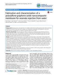
quantitively with Scotch tape tests35 according to the method of Strong.40 In order to be able to compare the characteristics of microreactors containing thin films of Pt/Ta or pure Pt, reactors with Pt/Ta films (200 nm/15 nm) in the SiRN-tubes were also fabricated with the above mentioned process. Measurement setup and experiment purposes The setup for characterization of the microreactors consisted of a modified probe station (Karl Su¨ss Som 4) to which a PCB with 40 spring-connectors (IDI-net SS-30-J-1.3-G) was attached to obtain a good electrical contact between the contact pads of the microreactor and the control equipment. On the table of the probe station a heating stage was mounted for heating the complete microreactor up to 70 uC for calibration purposes. For the determination of the electrical resistance of the 5 heaters and 12 temperature sensors of the microreactor, a multiplexed digital multimeter (MDMM) was used (Agilent 34970A—a 3-slot mainframe with built-in 6.5 digit multimeter). This MDMM contained two 20-channel multiplexer modules (Agilent 34901A) and a 4 6 8 matrix module (Agilent 34904A). The resistance of the heaters and temperature sensors was measured in a 4-point configuration. The currents flowing through the heaters were measured on resistances put in series (y4 V). The power applied to the heaters of the microreactor and the external heater (on the table of the probe station) was generated by 2 power sources (Agilent E3631). The matrix module (Agilent 34904A) enabled all 5 heaters to be connected independently to the power source. All equipment was computer-controlled via a GPIB-bus. For control and readout as well as calibration, Agilent Vee Pro code was written. Exposure to high temperatures has a large influence on the resistivity (r) and the temperature coefficient of resistance (TCR or a) of the thin films: due to grain growth and agglomeration, the electrical properties of the thin films will drift. Furthermore, the annealing conditions (time, temperature etc.) and history of the thin film will have an influence on the amount of grain changes in a thin film and hence on the values of a and r. The linearity of the R,T-relation, a and r were examined in microreactors with 2 metal thin films: sputter deposited 10 nm Ta/200 nm Pt and 200 nm pure Pt. In these microreactors 2 different heater shapes, implemented as SiRN-tubes, were used: sinusoidal and meandershaped heaters with a width of 150 mm. The main goal of this study was to determine which heater shape and which thin film composition has the best electrical high-temperature behaviour and, as a consequence, is the best choice for implementation in microreactors for the investigation of reaction kinetics of high-temperature reactions.
Three types of high-temperature experiments were performed in air: power–film calibration tests: experiments in which the supply power P is gradually increased to a maximum power (0.3–1.5 W), with in-between calibration of the thin films; endurance tests: experiments in which it is determined how long the thin film heaters are capable of dissipating a certain supply power P; maximum power tests: experiments in which the supply power P is increased untill the thin films were ruptured. Power–film calibration experiments The following protocol was used to determine a, r and verify the linear relation between R and T: different powers P were applied to the 5 heaters of the microreactor. The power P supplied to each of heaters was increased in steps of 30 mW (and was kept at this power level for 5 s) until a desired value of P was reached. P was kept stable at this value for 5 min before it was decreased in reversed order: 230 mW each 5 s. After each heating and cooling sequence of the thin film heaters, the filaments were calibrated. By means of an external heating stage the complete microreactor was heated. During heating, the resistance of all heaters was monitored as a function of the temperature (over 20–70 uC); the temperature of the microreactor was measured with a thermocouple. From these calibration runs the values of a and r were determined. Furthermore, the influence of the supplied heater power on the linearity of the R,T-relation was obtained. In Fig. 8 the results for a and r are summarized. It is noted that the values for r and a are averaged values for
Experiments on microreactors with suspended heaters Several microreactors were fabricated. Prior to hightemperature experiments the effective resistance of the asdeposited thin film heater structures was measured. The values were in the range 100–125 V. The as-deposited resistance is well in the range of calculated values of 120 ¡ 20 V based on the known resistivity of Pt. 332 | Lab Chip, 2005, 5, 326–336
Fig. 8 Resistivity (r) and temperature coefficient of resistance (a) as a function of supplied heater power P for 150 mm wide heaters of Pt/Ta (200 nm/10 nm) and Pt (200 nm). Values of r and a are obtained from calibration runs (over a temperature range of 20–70 uC) measured after heating up the thin films with power P.
This journal is ß The Royal Society of Chemistry 2005
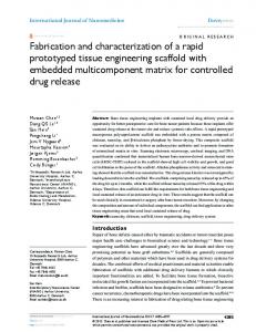
3 microreactors, each containing 5 heating filaments. For identical film compositions, values for r and a were found to be independent of the heater shape. As can be seen, a and r of the as-deposited thin films change as a result of heating. It indeed seems that the electrical behaviour expressed in the values of a and r of thin films highly depends on annealing conditions. Whereas r of Pt/Ta films are fairly constant for supplied heater powers over the range 0.4–1.4 W, r-values for pure Pt-films show a linear relation with a negative slope with the supply power P. However, r-data for Pt/Ta films have quite large error margins for P . 1.0 W, which tend to less reliable resistance values at high(er) temperatures. Therefore, use of Pt/Ta thin films in high-temperature microreactors might cause control problems, like a slow response to temperature rise, which is disastrous for controlling exothermic reactions. The TCR for both film compositions show a linear correlation with the supply power. However, the TCR of pure Pt-films is higher than that of Pt/Ta films. This indicates that the use of pure Pt films is preferable for monitoring the temperature in the microreactor: this film has the highest sensitivity to resistance variations. The overall conclusion of Fig. 8 is that both thin films are subject to ‘unpredictable’ electrical drift: trendlines for Pt/Ta and Pt are not linear over the complete P-range and especially Pt/Ta has large error margins for higher powers. The more the trends in a and r diverge from linear relations or the larger the error margins, the more difficult it is to gain reliable T,P-data from R,P-measurements. Based on these aspects and on the physical degradation in and drift in the electrical properties of these films at temperatures up to 950 uC (published elsewhere35), pure Pt films are more attractive to use in microreactors for high-temperature operations. Calibration of the thin films after each P-step revealed that the R,T-relation was linear. With the found calibration data, the maximum temperature reached in the heaters (Tmax,heater) during each P-step is calculated. In Fig. 9 the maximum temperature obtained in a heater is shown as a function of supply power P. Values of Tmax,heater are calculated with calibration data for a and r and a linear R,T-relation: after supply of power P to the heaters, measurements/calibration showed that the R,T-relation remains linear after heating, but that the values for a and r change (Fig. 8). As can be seen in Fig. 9, above 0.5 W supply power, the maximum temperature obtained with Pt/Ta films is lower than that obtained in pure Pt films. It is assumed that this is the result of a higher overall level of electrical drift in Pt/Ta films. The consequence of drift in the electrical properties is that for accurate temperature information and control of the heater supply power, thin film heaters and temperature sensors need to be calibrated after every experiment. However, the TCR and resistivity of the thin film are stable for several hours when the maximum operation temperature is below a so-called ‘burn-in’ temperature (Tburn-in). This aspect is further discussed below. Endurance experiments The endurance of the thin film heaters was investigated by determining the period that a thin film is capable of dissipating This journal is ß The Royal Society of Chemistry 2005
Fig. 9 Calculated maximum heater temperatures (Tmax,heater) as a function of supplied power for heaters of 200 nm/10 nm Pt/Ta and 200 nm pure Pt (estimations with calibration data found after supplying power P to the heaters).
a constant supply power. The supply power was y1.7 W, resulting in heater temperatures above 500 uC. Prior to these experiments a power of 1.8 W was supplied to the filaments and before starting the endurance test all heaters were calibrated as described earlier. In Fig. 10 the results for 2 different thin film compositions are shown. The supply power to the heaters (Pheater) and the normalized resistance of the heaters (Rheater,normalized) are stable for a long time: they fluctuate slightly around 1.7 W and 1.0, respectively. Heaters composed of 10 nm Ta and 200 nm Pt failed after 27.5 ¡ 0.5 h (average over 5 heaters). Inspections yielded that this failure was due to severe grain agglomeration in the Pt/Ta films, and the films were converted into a collection of electrically isolated islands. The endurance experiment of heaters of 200 nm pure Pt was terminated after a non-stop test of 110 h. Subsequently, the pure Pt heaters were calibrated. The values of a and r were 4.20 6 1023 uC21 and 18.38 mV cm, which is very close to the values prior to the endurance test (4.17 6 1023 uC21 and 18.01 mV cm, respectively). During these endurance experiments, the pure Pt heaters started to glow with a dark, orange colour, while the heaters of Pt/Ta did not glow. By extrapolation of the curves in Fig. 9, the temperature of the heaters are estimated: 515–525 uC for the Pt/Ta structures and 625–630 uC for the pure Pt heaters, respectively. Thin film structures indeed start to glow above y600 uC.41
Fig. 10 Normalized heater resistances (Rheater,normalized) as a function of time for 200 nm/10 nm Pt/Ta and 200 nm pure Pt heaters during duration experiments (Py1.7 W).
Lab Chip, 2005, 5, 326–336 | 333
For endurance experiments at temperatures of 775 ¡ 25 uC (determined with a pyrometer) it was found that the resistance of heaters of pure Pt becomes unstable after y10 h of nonstop operation; Pt/Ta heaters could not be operated at these temperatures. Based on these reproducible results, it is concluded that a and r of thin films are stable for at least several tens of hours when the maximum operation power is below a burn-in power Pburn-in. When the thin film is heated to a temperature Tburn-in using the power Pburn-in, an unspecified but reproducible amount of film agglomeration occurs. If the film is subsequently operated at temperatures lower than Tburn-in (thus Poperation , Pburn-in), agglomeration proceeds only slowly, such that drift in the electrical properties is low: a and r can be considered as constant for a period of time. The length of this period is influenced significantly by the composition of the thin film. Maximum power experiments The maximum power that the heaters can dissipate is studied with experiments during which the power supply to the heaters was increased continuously untill failure occurred. The power P supplied to each of the heaters was increased in steps of 10 mW per 5 seconds. During these experiments no distinction was found between sinusoidal or meandershaped heaters. In Fig. 11 results of these maximum supply power experiments are shown. Thin films of pure Pt failed at a power of 2.02 W, while Pt/Ta heaters could dissipate 2.74 W before they failed. Since the pure Pt heaters were first used for endurance experiments, they failed at a power of ‘only’ 2.02 W; for the maximum test of Pt/Ta heaters new, as-deposited thin films were used. With measured calibration data and Fig. 8, the maximum temperatures reached in the heaters were calculated: y650 uC for pure Pt and y750 uC for Pt/Ta thin films. The estimations of these temperatures seem, however, not to be very reliable: the used calibration values (for a and r) were obtained after heating with 1.5 W. Since it is shown that these values highly depend on the composition of the thin film and the annealing conditions (Fig. 8) as well as the history of the film,35 it is believed that the values of a and r used for estimations of the
Fig. 11 Heater resistance (Rheater) as a function of supplied heater power (Pheater) for heaters of 200 nm/10 nm Pt/Ta and 200 nm pure Pt—area’s with dotted and dashed lines indicate different temperature ranges of glowing heaters.
334 | Lab Chip, 2005, 5, 326–336
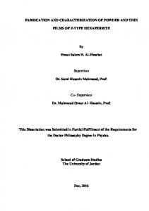
temperature close before heater-failure are inaccurate, resulting in too low estimations of the maximum temperature of the heaters. In fact, just before heater-failure the colour of the filaments rapidly changed from dark orange to bright orange. This was directly followed by a white flash at one spot of the heater, after which the electrical circuit of the heaters turned out to be disrupted. The range of observed heater colours indicate that the temperature locally increased to values well above 1000 uC. Inspection of the spots where the heaters failed confirmed that very high temperatures were reached just before heater failure. In Fig. 12 typical SEM-pictures of spots where the heaters failed are shown. At the spots where the heater failed a throughhole is visible. At these spots, the complete SiRN-film of y1 mm and the metal-film simply disappeared, indicating that extremely high temperatures are reached at failure-spots. Note that the melting points of Pt and SiRN are y1768 uC and y1900 uC, respectively.42 Moreover, close to the hole some blisters and melt droplets are visible. Other aspects that may have caused heater failure occur at lower temperatures, like sublimation and/or oxidation reactions. The flecked, shiny spots on the silicon near the tubes (Fig. 12(a)–(b)) are possibly evidence for the formation of volatile Pt-species and subsequent oxidation of these species. In conclusion, microreactors based on SiRN-tubes with corrugated zones are not ruptured due to electrical breakdown of the SiRN nor due to high thermally induced stresses, so the design perfectly meets the thermo-mechanical and thermoelectrical requirements. Failure of microreactors with SiRNtubes containing corrugated zones and pure platinum thin films occured due to agglomeration of the thin films. This degradation of thin films also leads to drift in electrical properties of the films.
Summary and conclusions In this paper, the fabrication of a microreactor for hightemperature reactions—catalytic partial oxidation reactions— was discussed. The microreactor has SiRN-tubes that are suspended in the flow channel. These tubes contain metal thin films that are used for heating of gases and temperature sensing. The metal films are well-defined by a built-in shadow mask. Furthermore, a new method to obtain well-defined pure Pt thin films with good adhesive properties was presented. The microreactors were subjected to a variety of high temperature experiments, like calibrations of thin films after heating sessions, endurance tests at temperatures above 525 uC and experiments in which the maximum power that thin films can dissipate is examined. Clearly, high temperatures have a large influence on the values of resistivity and temperature coefficient of resistance as well as on the linearity of the R,T-relation of thin Pt films. However, r and a were found to be stable for at least several tens of hours when, prior to hightemperature use, the thin films are, for several minutes heated to a level slightly above a burn-in temperature. If the thin film is subsequently operated at temperatures below this temperature, film aggregation proceeds slowly, such that electrical properties can be considered constant under operational conditions. This journal is ß The Royal Society of Chemistry 2005
agglomeration of thin films. The overall result of these phenomena, failure of the thin films, cannot be prevented, it can only be delayed, e.g. by omission of Pt adhesion layers. Finally, from the experiments it can be concluded that the new concept of suspended heaters of pure Pt thin films buried in SiRN-tubes with corrugated zones allows the realization of microreactors that can be operated reliably and safely for more than 20 h at temperatures up to 700 uC. The presented microreactors can be operated at 800 uC for up to 10 h, which is long enough to use them as a ‘tool’ for research on reaction kinetics of direct methane CPO or other reactions at such high temperatures.
Acknowledgements This work was supported by the Dutch Technology Foundation (STW—project ‘FORSiM’, nr. EFC.5134), Shell Global Solutions International B.V. and Netherlands Energy Research Foundation (ECN). H.D Tong is thanked for his assistance during AFM measurements. R. M. Tiggelaar,*a J. W. Berenschot,a J. H. de Boer,a R. G. P. Sanders,a J. G. E. Gardeniers,b R. E. Oosterbroek,b A. van den Bergb and M. C. Elwenspoeka a Transducers, Science Technology Group, MESA+ Research Institute, University of Twente, P.O. Box 217, 7500 AE, Enschede, The Netherlands. E-mail:
[email protected] b BIOS The Lab-on-a-Chip Group, MESA+ Research Institute, University of Twente, P.O. Box 217, 7500 AE, Enschede, The Netherlands
References
Fig. 12 SEM-pictures of suspended SiRN-heaters containing 200 nm pure Pt films subjected to maximum power experiments: (a) meandershaped tube, (b) sinusoidal shaped tube, (c),(d) zoom-ins on spots where heaters failed.
Experiments showed that pure Pt is the best choice for implementation in microreactors suitable for high-temperature experiments. However, like any other metal thin film, pure Pt films also have a limited lifetime due to the inevitable This journal is ß The Royal Society of Chemistry 2005
1 K. F. Jensen, Chem. Eng. Sci., 2001, 56, 293. 2 W. Ehrfeld, V. Hessel and H. Lo¨we, Microreactors: new technology for modern chemistry, Wiley VCH Verlag, Weinheim, Germany, 2000. 3 R. Srinivasan, I.-M. Hsing, P. E. Berger, S. L. Firebaugh, M. A. Schmidt, M. P. Harold, J. J. Lerou and J. F. Ryley, AIChE J., 1997, 43, 3059. 4 C. Ale´pe´e, L. Vulpescu, P. Cousseau, P. Renaud, R. Maurer and A. Renken, Meas. Control, 2000, 33, 265. 5 T. Becker, S. Mu¨hlerberger, C. Bosch-v.Braunmu¨hl, G. Mu¨ller, A. Meckes and W. Benecke, J. Microelectromech. Syst., 2000, 9, 478. 6 L. R. Arana, S. B. Schaevitz, A. J. Franz, M. A. Schmidt and K. F. Jensen, J. Microelectromech. Syst., 2003, 12, 600. 7 A. V. Pattekar and M. V. Kothare, J. Microelectromech. Syst., 2004, 13, 7. 8 J. A. Plaza, M. J. Lo´pez-Bosque, I. Gra´cia, C. Cane´, J. Wo¨llenstein, G. Ku¨hner, G. Plescher and H. Bo¨ttner, IEEE Sens. J., 2004, 4, 195. 9 R. M. Tiggelaar, P. van Male, J. W. Berenschot, J. G. E. Gardeniers, R. E. Oosterbroek, M. H. J. M. de Croon, J. C. Schouten, A. van den Berg and M. C. Elwenspoek, Sens. Actuators, A, 2004, accepted. 10 R. M. Tiggelaar, P. W. H. Loeters, P. van Male, R. E. Oosterbroek, J. G. E. Gardeniers, M. H. J. M. de Croon, J. C. Schouten, M. C. Elwenspoek and A. van den Berg, Sens. Actuators, A, 2004, 112, 267. 11 P. van Male, M. H. J. M. de Croon, R. M. Tiggelaar, A. van den Berg and J. C. Schouten, Int. J. Heat Mass Transfer, 2004, 47, 87. 12 J. H. Jerman, Sens. Actuators, A, 1990, 23, 988. 13 V. L. Spiering, S. Bouwstra and R. M. E. J. Spiering, Sens. Actuators, A, 1993, 39, 149. 14 P. R. Scheeper, W. Olthuis and P. Bergveld, J. Microelectromech. Syst., 1994, 3, 36. 15 V. L. Spiering, S. Bouwstra and J. H. J. Fluitman, Sens. Actuators, A, 1993, 37, 800.
Lab Chip, 2005, 5, 326–336 | 335
16 V. L. Spiering, J. W. Berenschot and M. Elwenspoek, J. Micromech. Microeng., 1995, 5, 189. 17 V. L. Spiering, J. W. Berenschot, M. Elwenspoek and J. H. J. Fluitman, J. Microelectromech. Syst., 1995, 4, 151. 18 J. G. E. Gardeniers, H. A. C. Tilmans and C. C. G. Visser, J. Vac. Sci. Technol., A, 1996, 14, 2879. 19 R. W. Tjerkstra, Isotropic etching of silicon in fluoride containing solutions as a tool for micromachining, PhD thesis, University of Twente, Enschede, The Netherlands, 1999. 20 M. J. de Boer, R. W. Tjerkstra, J. W. Berenschot, H. V. Jansen, G. J. Burger, J. G. E. Gardeniers, M. Elwenspoek and A. van den Berg, J. Microelectromech. Syst., 2000, 9, 94. 21 E. Sarajlic, M. J. de Boer, H. V. Jansen, N. Arnal, M. Puech, G. Krijnen and M. Elwenspoek, J. Micromech. Microeng., 2004, 14, S70. 22 Alcatel Vacuum Technology, ‘‘I-speeder’’—the advanced deep plasma etching tool, Annecy, France, 2004; www.adixen.com. 23 J. A. Appels, E. Kooi, M. M. Paffen, J. J. H. Schatorje and W. H. C. G. Verkuylen, Philips Res. Repts., 1970, 25, 118. 24 R. M. Tiggelaar, J. W. Berenschot, R. E. Oosterbroek, P. van Male, M. H. J. M. de Croon, J. C. Schouten, A. van den Berg and M. C. Elwenspoek, in Techn. Digest 12th International Conference on Solid-state Sensors and Actuators, Boston, MA, USA, June 8–12, 2003, p. 746. 25 R. M. Tiggelaar, J. G. E. Gardeniers, J. W. Berenschot, R. E. Oosterbroek, P. van Male, M. H. J. M. de Croon, J. C. Schouten, A. van den Berg and M. C. Elwenspoek, J. Vac. Sci. Technol., B, 2004, submitted. 26 G. Wallis and D. I. Pomerantz, J. Appl. Phys., 1969, 40, 3946. 27 H. Wensink and M. C. Elwenspoek, Sens. Actuators, A, 2002, 102, 157.
336 | Lab Chip, 2005, 5, 326–336
28 P. D. Hren, H. Al-Shareef, S. H. Rou, A. I. Kingon, P. Buaud and E. A. Irene, Mater. Res. Soc. Symp. Proc., 1992, 260, 575. 29 J.-S. Lee, H.-D. Park, S.-M. Shin and J.-W. Park, J. Mater. Sci. Lett., 1997, 16, 1257. 30 S. L. Firebaugh, K. F. Jensen and M. A. Schmidt, J. Microelectromech. Syst., 1998, 7, 128. 31 K. G. Kreider and G. Gillen, Thin Solid Films, 2000, 376, 32. 32 D. Briand, S. Heimgartner, M. Leboeuf, M. Dadras and N. F. de Rooij, Mater. Res. Soc. Symp. Proc., 2002, 729, U2.5.1. 33 M. P. Moret, M. A. C. Devillers, F. D. Tichelaar, E. Aret, P. R. Hageman and P. K. Larsen, Thin Solid Films, 2003, 434, 283. 34 M. S. Spencer, Surf. Sci., 1998, 145, 145. 35 R. M. Tiggelaar, J. G. E. Gardeniers, A. W. Groenland, R. G. P. Sanders, J. W. Berenschot and M. C. Elwenspoek, J. Mater. Res., 2004, submitted. 36 D. S. Lee, D. I. Chun, D. Y. Park, J. W. Ha, E. J. Yoon, M. H. Kim and H. J. Woo, United States patent, nr. 5.736.422, April 1998. 37 H. J. Woo, D. Y. Park, D. S. Lee, D. I. Chun and E. J. Yoon, United States patent, nr. 6.054.331, April 2000. 38 M. J. Kim, L. A. Gruenke, R. J. Saia and S. S. Cohen, Appl. Phys. Lett., 1984, 33, 462. 39 J. L. Vossen and W. Kern, Thin film processes, Academic Press, London, UK, 1978. 40 J. Strong, Rev. Sci. Instrum., 1935, 6, 97. 41 C. Ale´pe´e, Technologies for high-temperature silicon microreactors, ´ cole polytechnique fe´de´rale de Lausanne, Lausanne, PhD thesis, E Switzerland, 2000. 42 D. R. Lide, Handbook of chemistry and physics, 77th edn., CRC Press Inc., New York, NY, USA, 1996.
This journal is ß The Royal Society of Chemistry 2005