Proceedings of the ASME 2016 International Mechanical Engineering Congress and Exposition IMECE2016 November 11-17, 2016, Phoenix, Arizona, USA
IMECE2016-67314
FABRICATION PARAMETERS AND PERFORMANCE RELATIONSHIP OF TWISTED AND COILED POLYMER MUSCLES
Lokesh Saharan Humanoid, Biorobotics and Smart systems (HBS) Laboratory, Department of Mechanical Engineering The University of Texas at Dallas Richardson, Texas - 75080, USA
[email protected]
Yonas Tadesse Humanoid, Biorobotics and Smart systems (HBS) Laboratory, Department of Mechanical Engineering The University of Texas at Dallas Richardson, Texas - 75080, USA
[email protected]
ABSTRACT
stroke and high energy per volume when compared to Shape Memory Alloy (SMA) and other smart materials. Another advantage of these materials is that they are cost effective, light weight, easy to manufacture and have both sensing and actuation capabilities. For all the aforementioned valid reasons, these materials can potentially revolutionize robotics, prosthetics, orthotics and other electrical and mechanical systems.
Twisted and Coiled Polymer (TCP) muscles are soft actuators made by inserting twist in a precursor fiber while attaching a dead weight at the end, followed by heat treatment. TCP muscles are thermally driven actuators with high power to weight ratio, large strain and low cost. These muscles have a wide variety of applications in engineering, specifically for robotics since these actuators have large linear deformation in response to applied power (Joule’s Effect). The performance of these muscles depend on numerous fabrication parameters such as speed of the coiling, dead weight used, precursor fiber type, number of filament in precursor fiber, number of plies and training cycles. An in-depth study of the fabrication parameters is required to understand the performance of the muscles. We have designed experimental setup to study the performance of the muscles on different input parameters such as load, current, voltage and output results such as displacement, force and temperature. We present the study of single, double and tripled plied muscles that are fabricated by plying together a twisted and coiled filament. Further, the power consumption of the muscles under various conditions is discussed. This study would help to establish a procedure to fabricate these materials with consistent properties. Keywords: Soft Actuator, Robotics, Artificial Muscles, fabrication, Smart material.
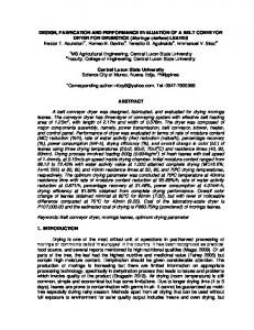
When a procurer fiber is twisted, coiled, annealed and trained, it will result in a one ply muscle. The muscles can be plied or braided together in order to get higher stresses. Typically, a single ply muscle has large stroke and less stress as compared to a three ply muscle that has higher stresses and lower stroke. Figure 1 shows the three different types of TCP muscles fabricated for our studies.
Figure 1: Three different types of TCP muscles. 1-ply (diameter 920 μm diameter, 2-ply (1260 μm diameter) and 3-ply (of 1720 μm diameter)
I. INTRODUCTION Artificial polymer muscle from fishing line and silver coated nylon muscle was recently reported by Haines et al. [1]. These artificial muscles can be fabricated by adding twist insertion into a precursor fiber and heat treatment. These Twisted and Coiled Polymeric (TCP) muscles provide a large
TCP muscles produce high untwisting torques while subjected to heat and hence produce a large linear stroke. This linear stroke can be as high as 49% under 1 MPa stress [1]. The direction of twist insertion plays a vital role in the behavior of these materials.
1
Copyright © 2016 by ASME
Downloaded From: http://proceedings.asmedigitalcollection.asme.org/pdfaccess.ashx?url=/data/conferences/asmep/91008/ on 03/06/2017 Terms of Use: http://www.asme.org/abo
Different researchers have reported different results on the TCP muscles. Cherubini et al. [4] and Moretti et al. [2] have shown a strain of 50% at 80 MPa using a fiber diameter of 0.5 mm fishing line muscle, whereas Mirvakili et al. [5] have used two different size precursor fibers (188 µm and 296 µm) that are painted with silver and reported 29 % of actuation at 4.1 MPa stress with regard to coil area (equal to 26.8 MPa when normalized with the precursor fiber diameter). They also reported 10% actuation for 2-ply muscle at 4.1 MPa. Kianzard et al. [8] have reported 20 % of strain at 20 MPa using a silver coated nylon precursor fiber of 294 µm. But they have clearly mentioned that the coiled diameter becomes 2.25 times the original diameter of the fiber, so the effective stresses would be around 4-5 MPa. In similar studies, Wu et al. [13] have reported 22 % strain for 200 gm load for a muscle made of 860 µm precursor fiber diameter that resulted in a coil diameter of 3.33 mm, using hot water to actuate the fishing line muscle. Similarly, Yip and Niemeyer [12] have reported 10% actuation at 1 N force using a precursor fiber diameter of 720 µm.
Fully coiled homochiral (twisted in anticlockwise direction) have negative thermal expansion coefficient and hence they contract linearly when heated. Whereas heterochiral fibers (twisted in clockwise direction) have a positive thermal expansion coefficient. These properties are independent of the axial thermal expansion coefficient of the precursor fiber; they are the result of twist insertion direction. All these properties make these materials, interesting, unique and useful as actuators. The TCP muscles are introduced recently and we do not know much about the muscles compared to other smart materials. Studying the different parameters of these materials would help our understanding of the structure-propertyperformance relationships. Few research groups have presented experimental [2-5] and phenomenological modeling [6] and characterization results. Kianzard et al. have recently presented their studies on operating temperature ranges and stiffness [3, 7] of the muscles apart from designing a variable stiffness structure[8]. While Aziz et al., [9] have presented torsional actuation and Yue et al., [10] have presented the effective Young’s modulus of the muscle. Interestingly, Kim et al., [11] have used the properties of the coiled nylon to extract a waste energy out of fluctuating energy cycles and showed the use of the material as energy harvesting system. Yip and Niemeyer, and Wu et al., [12, 13] have worked on the robotic application of these muscles. Few researchers have reported and measured certain degree of hysteresis in TCP muscles. We have also conducted the experiment in very similar manner and used Joule’s heating to actuate the muscle, unlike Cherubini et al. [4] who used hot air to perform isothermal and isometric tests and Wu et al., [13] who used hot water to actuate the fishing line muscle.
In our recent work [14], we have presented the study of the TCP muscles, which have shown a linear relationship between displacement and force output, with very low or no hysteresis. As an extension to our previous work, we have conducted further study on the fabrication process of the muscle in order to understand the effect of various parameters on performance of the muscle. In this study, we have fabricated the muscles at four different speeds 200, 600, 1000 and 1800 RPM using a standard DC motor for twisting and coiling of the precursor fiber. The fabrication setup and process will be explained later in the paper. For understanding of the muscle, we have provided the fabrication parameters from various research groups in Table 1.
Table 1 Various muscle fabrication parameters used by different investigators. Authors
Type of Muscle
Stresses/ Load
Fiber Diameter
Annealing Temperature
Method
Medium
76,-2450 µm
Annealing Time/ Cycle Variable
Haines et al.[1]
Fishing Line/ Silver Coated Nylon
Wu et al. [13]
Fishing Line
Variable (Diameter Dependent) 900g
Variable
Constant Temp.
Air
800 µm
2 hrs
1800 C
Air
Yip et al.[12] Cherubini et al. [4]
Silver Coated Nylon Silver Coated Nylon
50g 25 MPa
720 µm 500 µm
20 Cycle 1 hr
1500 C 1500 C
Moretti et al.[2]
Silver Coated Nylon
25 MPa
500 µm
1 hr
1500 C
Kianzad et al.[7]
Silver Coated Nylon
21 MPa
294 µm
30 min
180 C
Mirvakili et al [5].
Silver Painted Nylon
1-9 N
20 Cycle
N/A
Tadesse et al.[14] Saharan et al. (This paper)
Silver Coated Nylon Silver Coated Nylon
120 g 125 g
180 µm / 296 µm 180 µm 200 µm
Constant Temp. Joule Heating Constant Temp. Constant Temp. Constant Temp. Joule Heating
30 Cycle Varying
Variable Variable
Joule Heating Joule Heating
2
0
Air Air Air Nitrogen Air Air Air
Copyright © 2016 by ASME
Downloaded From: http://proceedings.asmedigitalcollection.asme.org/pdfaccess.ashx?url=/data/conferences/asmep/91008/ on 03/06/2017 Terms of Use: http://www.asme.org/abo
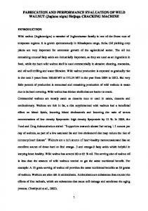
II. MUSCLE FABRICATION PROCESS The muscle fabrication process involves three major steps: (1) Twist insertion and coiling (2) Annealing (3) Training. The performance of the muscle is dependent on how carefully the three steps were carried out. Improper twisting and coiling can cause different defects in the muscles. For example, it may results in slippage of axis of the coil that can affect the life of the muscle whereas improper annealing can cause hysteresis. Our muscle fabrication process is similar to the one described by Haines et al. [1] except the annealing and training. Fig. 2 shows a typical muscle fabrication setup. For our muscle manufacturing, we have used a DC motor, a dead weight (125 g), tachometer, a computer controlled power supply and a PC. In a typical muscle fabrication process, we take the precursor fiber of a certain length usually thrice the desired length of the muscle, tie on side of the thread to a motor and another side to a dead weight of optimum value. The dead is used to keep the thread in tension during the twist insertion. The precursor fiber can be a silver coated nylon 6,6 or a fishing line. In this study, we have used a silver coated nylon 6,6 multifilament precursor fiber, diameter of 200 µm from Shieldex®. The value of the dead weight depends on the diameter and number of filaments in the precursor fiber. The weight used also affects the properties of the muscle; e.g. higher weight will give more spacing between coils, while less weight can give closely spaced muscles. But too small weight can cause snarling of the thread whereas large weight can break the fiber during the twist insertion.
Figure 2: Muscle Fabrication Setup.
Once appropriate dimensions are selected, twist insertion in fiber is performed in anticlockwise direction. During the twist insertion, after a sufficient number of twists get into the fiber and it can no longer take more twists, the fiber starts coiling on its own axis. The motor can be stopped when coiling is done throughout the muscle fabrication by visual inspection. But for automated system, one can use timer for the motor to stop coiling based on the RPM and length of the fiber. In our study, we have calculated the number of twist per mm and it is set to be 1.14. For example, for a 200 RPM motor and a 1 meter long precursor fiber, the timer was set to have 342 second and the motor stopped automatically when coiling was done. The timer was set by a computer controlled power supply that was connected with the motor.
Figure 3: Muscle Annealing setup Schematic. In our case, we have applied electric power for joule heating. For the annealing, we have used the same weight as the one used for twist insertion and applied power depends on the length of the muscle. In fact the magnitudes of voltage or current are dependent on so many parameters such as convective heat transfer coefficient, room temperature, surface area of the coiled fiber. So, we need to establish mathematical relation in order to standardize the annealing or training process. In the current study, we have applied three annealing cycles at a particular voltage and repeated the cycles four times (12 cycles in total), then observed the change in length due to
Twist insertion is followed by annealing. Annealing is a typical process for stress relieving. Since twist insertion and coiling are cold working on the precursor fiber, mechanical stresses will develop in the fiber. So, for annealing, we need to fix the muscle to prevent unwinding and at the same time apply heat (joule heating).
3
Copyright © 2016 by ASME
Downloaded From: http://proceedings.asmedigitalcollection.asme.org/pdfaccess.ashx?url=/data/conferences/asmep/91008/ on 03/06/2017 Terms of Use: http://www.asme.org/abo
ply muscles using a 150 g, 2-ply with 300 g and 3- ply muscles with 450 g loads by suspending vertically (gravity directed downwards).
stress relieving. The reason for repeating the process four times was to completely get rid of the stresses completely. Figure 3 shows the schematic diagram of a typical muscle annealing setup, which contains a dead weight, a computer controlled power supply and a PC. During the annealing process, we observed a significant color and length change in the muscle after stress relieving due to annealing.
To determine the effect of motor speed during twisting and coiling, we have fabricated the muscles at four different RPM’s 200, 600, 1000 and 1800. Three samples (1-ply, 2-ply and 3ply) were fabricated for each speed. All the studies were done keeping other parameters fixed except the RPM of the motor. These muscles were later tested for the performance. All the parameters of muscle fabrication are listed in Table 2.
After annealing, we trained the muscles. The training was similar to the annealing except the load for training was determined by the later usage of the muscle. We have trained 1-
Property
Table 2 TCP muscle fabrication parameters used during this study 1-Ply 2-Ply 3-Ply
Precursor Fiber Diameter Precursor Fiber Length Coil Diameter = d Coiled Length No. of Twist per mm Total No. of Twists No. of Annealing Cycles, (Voltage) No. of Training Cycles Annealing Voltage based on length Length used for performance Testing* * The length of the muscle was cut to small size to measure the displacement because the range of our position sensor was limited up to 10mm.
200 µm 711 mm d = 920 µm 192 mm 1.14 810 12 (60s each)
200 µm 850 mm£ 1260 µm 244 mm 1.14 936x2 12 (60s each)
200 µm 711 mm (three 1-ply)€ 1720 µm 192 mm (3 quantity) 1.14 810 x 3 12 (60s each)
12 (30s each) 1.1 V / Length
12 (30s each) 1.1 V / Length
12 (30s each) 1 V / Length
95 mm
90 mm
92 mm
£
The 2-ply muscle was made by folding 1-ply long muscle into half. €
The 3-ply was made by plying together three 1-ply muscles.
III. MUSCLE PERFORMANCE TESTING
using the inductive displacement sensor during the actuation and relaxation of the TCP muscle. The whole experimental setup was mounted on an optical table. Temperature measurements were taken using K-type thermocouple by keeping it in physical contact with muscle at the endpoint. Hence, we were able to measure the surface temperature of the muscles. Few other researches have used other techniques like thermal imaging to measure the surface temperature of such muscles.
All the samples fabricated during the studies were tested using a custom made experimental setup shown in the schematic diagram shown in Fig. 4. The experimental setup consists of a force/load cell (Omega® LCL 10) for force measurement and an inductive displacement sensor (Omega® LD 701). A bias spring was used for the muscle to work against a load. A computer controlled power supply was used to actuate the muscle and a camera was used to record the video of the actuation. Fig. 5 shows the actual experimental setup. NI cDAQ was used to record the data from the sensors. A metal plate was mounted to the bias spring to detect the displacement
4
Copyright © 2016 by ASME
Downloaded From: http://proceedings.asmedigitalcollection.asme.org/pdfaccess.ashx?url=/data/conferences/asmep/91008/ on 03/06/2017 Terms of Use: http://www.asme.org/abo
spring of stiffness K= 90 N/m which was attached to the muscle. The profile of the force is triangular having a range of generated value between 0.112 N (Max. force – Pre-force) at 2 V and 0.935 N at 4.75 V. The value of the force may look small but again it depends on the amount of load applied for the muscle. (a) Figure 4: Schematic diagram of the experimental Setup.
(b)
Figure 5: Experimental setup used during the study.
(c)
IV. RESULTS AND DISCUSSION Several performance tests were carried out on all the samples of equal lengths and under similar applied voltage sequence of different amplitudes. Fig. 6 shows the typical time domain results of the test carried out on a 2-ply muscle fabricated at 600 RPM. We have used six different voltages for the muscle ranging from 2 V to 5 V (Fig. 6a), and the corresponding current can be observed from Fig. 6b, where the maximum current consumption of the actuator at 4.75 V was ~0.9 A. The measured force and displacement are provided in Fig. 6c and 6d respectively. The maximum force and displacement for the 4.7 V applied voltage on the 2-ply muscle were 2.8 N and 10 mm respectively. Since the length of the muscle was 89 mm as shown earlier in Table 2, the stroke or strain of the actuator was 11.2%, under an applied load of 1.8 N force (pre-stress). The stress in the 2-ply muscle can also be deduced from the force measurement and the stress normalized by the area of the precursor fiber was 90.3 MPa and the stress normalized by the coiled area was 1.72 MPa. A red circle is marked in the Fig. 6d, where the muscle showed a large displacement at 4.75 V and the saturation point due to the displacement sensor had a 10mm range limit. The maximum displacement corresponding to the smallest applied voltage 1.88 V was 1.07 mm which was increased to 9.56 mm for 4.75 V. Figure 6c shows the force profile generated by the muscle on a load cell in response to applied voltage against a passive
(d)
Figure 6: Time domain of the state variables for a 2-ply muscle of 89 mm fabricated at 1400 RPM under a dead weight of 175 g: (a) Voltage input provided to the muscle, (b) Current supplied to the muscle, (c) The force output of the muscle and (d) The displacement of the muscle. The speed of the motor used for the fabrication has a significant effect on the performance of the muscles. Fig. 7 shows the effect of the RPM on the force and strain at 4.5 V for all the three different muscles (1-ply, 2-ply and 3-ply).
5
Copyright © 2016 by ASME
Downloaded From: http://proceedings.asmedigitalcollection.asme.org/pdfaccess.ashx?url=/data/conferences/asmep/91008/ on 03/06/2017 Terms of Use: http://www.asme.org/abo
For instance, for the 1-ply muscle, the effective force (difference between the solid and dashed line) has the maximum values for samples fabricated at 200 and 1800 RPM, where the performance decreased significantly for the sample made at 600 RPM. While for 2-ply muscle, the force is quite opposite since the performance increases for 200 RPM until 1000 RPM, and then decreases slightly at 1800 RPM. However, for 3-ply muscle the force decreased from low speed to high speed with slight variation at 1000 RPM. In the force plot, the dashed trend line is the pre-load applied initially and the solid line is the trend of the force generated by the muscles. Since the samples have different spring stiffness, the pre-load forces are different for each sample. The pre-load forces are the force applied on the muscles by the bias spring during the rest position. The strain for 1-ply and 3-ply decreased as the speed increased, but for 2-ply a higher strain was obtained at 1000 RPM. The variation of the 2-ply muscle is likely due to the manufacturing method and needs further investigation. .
Figure 8: Power consumed and output of the muscles that are fabricated at different speed (RPM) of twist insertion and evaluated at an applied voltage of 4.5V.
Figure 8 shows the total power consumed and work done by the muscles at 4.5 V. The power consumed by the muscles was determined by multiplying the current with the voltage and the maximum work done by the muscles was obtained by multiplying maximum force with the maximum displacement. The power consumption is increased as number of ply increased, such that 3-ply consumes higher power than 1 ply and 2-ply. For 1-ply and 2-ply, the power decreases slightly afterwards and remains steady, where the case is quite opposite for the 3-ply muscle, which has a low power consumption at 200 RPM and increases afterward before becoming constant at 1000 and 1800 RPM. The maximum work output follows almost the similar pattern as power consumed except for the few cases, such that the work done is higher at 200RPM and 1800 RPM for 1-ply. But the 2-ply produced higher output work than 3-ply muscle in most cases.
Figure 7: Force and strain of 1-ply, 2-ply and 3-ply muscles that are fabricated at different speed (RPM) of twist. insertion on silver coated nylon precursor fibers.
The variation of the speed of twist insertion in the precursor fiber resulted in significant variation on the performance of the muscles. One of the reasons is the fabrication process of the muscles. Another likely reason is resonance effect that influences the performance. As the load
6
Copyright © 2016 by ASME
Downloaded From: http://proceedings.asmedigitalcollection.asme.org/pdfaccess.ashx?url=/data/conferences/asmep/91008/ on 03/06/2017 Terms of Use: http://www.asme.org/abo
used during coiling has a mass m and the stiffness of each muscle is k, the resonance frequency of each setup should be determined using the relationship. √ To determine natural frequency of the samples, the stiffness of each muscle was determined. The spring constants of annealed muscles were obtained by measuring the static deflection and suspending different loads for all three different types of muscles. The stiffness of the muscles were plotted using excel to determine the slope by curve fitting the raw data. Thus, the spring constants for different type of muscles at varying RPM were determined as shown in Fig. 9.
Figure 10: Effect of speed (RPM) of motor used for fabrication of muscles and natural frequency of 1-ply, 2-ply and 3-ply.
V. CONCLUSION A study was carried out to determine the influence of speed of twist insertion on a precursor fiber during fabrication of Twisted and Coiled Polymer (TCP) muscles and the associated performance of TCP muscles. We fabricated 1-ply, 2-ply and 3ply silver coated nylon muscles and determined the force and displacement, power, work done and natural frequency of samples. During this study, we observed that different performances at different speed (RPM) of the motor used to fabricate the muscles. In future, we will carry out more extensive study on the different fabrication parameters on muscle performance such as load used for muscle fabrication, number of filaments in precursor fiber and additional magnitude of speed, and the associated muscle performance.
Figure 9: Effect of speed (RPM) of motor used for fabrication of muscles and natural frequency of 1-ply, 2-ply and 3-ply. Then natural frequencies of the samples were obtained using Eq. (1). Since the stiffness of the muscles is already determined for each sample and the load used for coiling was 125 gram. The values of natural frequencies for the muscles were presented in Fig. 10. It can be seen in the figure that the natural frequencies of each sample are in the range of 2 to 6 Hz (vertical axis in Fig. 10) and the magnitudes of the speed of the motor during coiling were 200, 600, 1000 and 1800 RPM which correspond to 3.3, 10, 16.6, and 30 Hz. This means that the low speeds coiling of the samples are close to the natural frequency of the muscles which might result in variation of the performance of the muscles. The above analysis is assuming a string/cable loaded with a tip mass and considering axial vibration. However, torsional vibration of the structure in relation to the speed of the motor used for the coiling should be determined. We will investigate such aspect in the future.
ACKNOWLEDGMENT This work is supported by the Office of Naval Research (ONR), Young Investigator Program, under the grant number N00014-15-1-2503. REFERENCES [1] Haines, C. S., Lima, M. D., Li, N., Spinks, G. M., Foroughi, J., Madden, J. D., Kim, S. H., Fang, S., de Andrade, M. J., and Göktepe, F., 2014, "Artificial muscles from fishing line and sewing thread," science, 343(6173), pp. 868-872. [2] Moretti, G., Cherubini, A., Vertechy, R., and Fontana, M., "Experimental characterization of a new class of polymeric-wire coiled transducers," Proc. SPIE Smart Structures and Materials+ Nondestructive Evaluation and Health Monitoring, International Society for Optics and Photonics, pp. 94320P-94320P-94329. [3] Kianzad, S., 2015, "A treatise on highly twisted artificial muscle: thermally driven shape memory alloy yarn and coiled nylon actuators "
7
Copyright © 2016 by ASME
Downloaded From: http://proceedings.asmedigitalcollection.asme.org/pdfaccess.ashx?url=/data/conferences/asmep/91008/ on 03/06/2017 Terms of Use: http://www.asme.org/abo
Master of Applied Science, The University of British Columbia, Vancouver. [4] Cherubini, A., Moretti, G., Vertechy, R., and Fontana, M., 2015, "Experimental characterization of thermally-activated artificial muscles based on coiled nylon fishing lines," AIP Advances, 5(6), p. 067158. [5] Mirvakili, S. M., Ravandi, A. R., Hunter, I. W., Haines, C. S., Li, N., Foroughi, J., Naficy, S., Spinks, G. M., Baughman, R. H., and Madden, J. D., "Simple and strong: Twisted silver painted nylon artificial muscle actuated by Joule heating," Proc. SPIE Smart Structures and Materials+ Nondestructive Evaluation and Health Monitoring, International Society for Optics and Photonics, pp. 90560I-90560I-90510. [6] Sharafi, S., and Li, G., 2015, "A multiscale approach for modeling actuation response of polymeric artificial muscles," Soft matter, 11(19), pp. 3833-3843. [7] Kianzad, S., Pandit, M., Bahi, A., Ravandi, A. R., Ko, F., Spinks, G. M., and Madden, J. D., "Nylon coil actuator operating temperature range and stiffness," Proc. SPIE Smart Structures and Materials+ Nondestructive Evaluation and Health Monitoring, International Society for Optics and Photonics, pp. 94301X-94301X-94306. [8] Kianzad, S., Pandit, M., Lewis, J. D., Berlingeri, A. R., Haebler, K. J., and Madden, J. D., "Variable stiffness structure using nylon actuators arranged in a pennate muscle configuration," Proc. SPIE Smart Structures and Materials+ Nondestructive Evaluation and Health Monitoring, International Society for Optics and Photonics, pp. 94301Z-94301Z-94305. [9] Aziz, S., Naficy, S., Foroughi, J., Brown, H. R., and Spinks, G. M., 2015, "Characterisation of torsional actuation in highly twisted yarns and fibres," Polymer Testing, 46, pp. 88-97. [10] Yue, D., Zhang, X., Zhou, J., and Zhou, Y.-H., 2015, "Effective Young’s modulus of the artificial muscle twisted by fishing lines: Analysis and experiment," AIP Advances, 5(9), p. 097113. [11] Kim, S. H., Lima, M. D., Kozlov, M. E., Haines, C. S., Spinks, G. M., Aziz, S., Choi, C., Sim, H. J., Wang, X., and Lu, H., 2015, "Harvesting temperature fluctuations as electrical energy using torsional and tensile polymer muscles," Energy & Environmental Science, 8(11), pp. 3336-3344. [12] Yip, M. C., and Niemeyer, G., "High-performance robotic muscles from conductive nylon sewing thread," Proc. Robotics and Automation (ICRA), 2015 IEEE International Conference on, IEEE, pp. 2313-2318. [13] Wu, L., de Andrade, M. J., Rome, R. S., Haines, C., Lima, M. D., Baughman, R. H., and Tadesse, Y., "Nylon-muscle-actuated robotic finger," Proc. SPIE Smart Structures and Materials+ Nondestructive Evaluation and Health Monitoring, International Society for Optics and Photonics, pp. 94310I-94310I-94312. [14] Tadesse, Y., Wu, L., and Saharan, L. K., 2016, "Musculoskeletal system of bio-inspired robotic systems," mechanical engineering, 138(3).
8
Copyright © 2016 by ASME
Downloaded From: http://proceedings.asmedigitalcollection.asme.org/pdfaccess.ashx?url=/data/conferences/asmep/91008/ on 03/06/2017 Terms of Use: http://www.asme.org/abo