Feasibility of Interactive Localization and Navigation of People with Visual Impairments Ilias APOSTOLOPOULOS, Navid FALLAH, Eelke FOLMER and Kostas E. BEKRIS 1 Computer Science and Engineering Department, University of Nevada, Reno Abstract. Indoor localization and navigation systems for individuals with visual impairments (VI) typically rely upon extensive augmentation of the physical space or expensive sensors. Thus, few systems have been adopted. This work conducts a feasibility study of whether it is possible to localize and guide people with VI using inexpensive sensors, such as compasses and pedometers, which are available in portable devices like smart phones. The proposed approach takes advantage of interaction between the system and the human user, who confirms the presence of landmarks. Experiments are employed to study what kind of directions are successful in assisting human users to reach their destination. These experiments show that Bayesian localization tools provide sufficient accuracy, while achieving realtime operation, despite the minimalistic, noisy nature of sensors and the limited computational resources available on smart phones. Keywords. Human-Centered Intelligent Autonomous Systems, Sensor Fusion, Localization, Embodied Intelligence, Interactive Systems
1. Introduction Whereas sighted people primarily use vision to navigate, individuals with Vision Impairments (VI) employ compensatory senses (e.g., touch), resulting in reduced mobility. To address this issue, a number of navigation systems have been developed. Outdoor systems rely upon GPS, which is not available indoors. Indoor solutions often require physical augmentation of the environment, such as RFID tags. Though RFID tags are cheap, they are typically embedded in floors with a resolution of several tags per square feet [1]. Though embedding tags in carpets is feasible, hallways or large open spaces often have tiles or concrete floors which makes installing tags prohibitively expensive. Alternatives utilize sophisticated sensors, such as cameras or laser-rangefinders, which are expensive and may impede mobility due to weight [2]. This paper proposes a low-cost solution that does not require physical augmentation and depends on affordable, light-weight sensors, such as a pedometer and a compass, that are already available on popular devices, such as smart phones. The approach utilizes interaction with the user through an audio/speech interface to provide directions using landmarks that are recognizable by individuals with VI, such as doors, hallway intersections and floor transitions. The user confirms the presence of the landmarks along the provided path through a smart phone, based on the Android OS. This allows the system to track the user’s location by using the sensor readings, knowledge of the indoor environment and the user’s landmark confirmations. The premise of the approach is that: 1 Kostas E. Bekris, CSE, UNR, 1664 N. Virginia St., MS 171, 89557, Reno, NV; E-mail:
[email protected].
• Individuals with VI are effective in recognizing landmarks through touch, for example using a cane, in their daily navigation [3, 4]. The proposed system, through interaction with the user, employs these landmarks to guide the users and track one’s location. • Indoor spaces, while complex, are often highly constrained. For example, a human has to cross a door to enter a room, an easily recognizable event by a user with VI. Veering is less likely to occur in hallways due to the presence of walls. • While compasses and pedometers are erroneous, when integrated in the proposed overall scheme, they provide a sufficiently good initial estimate for the user’s motion. The first objective is to show that the overall scheme succeeds with in guiding a user with VI to a desired destination in an indoor environment. The localization approach utilizes Bayesian tools based on particle filters and is able to track the user employing the limited resources of portable devices. Each particle estimates the user’s location and carries a weight of how probable this estimate is. As the user moves, each particle is updated based on data received from sensors, using the map of the environment to prune improbable transitions and landmark confirmations to recompute weights. Resetting techniques are employed in the case the weight of all particles is equal to 0. The second objective is to emphasize that the method’s performance depends on the directions provided to the user. Thus, this paper compares the effects of different types of instructions varying from metric-based commands, where the user is instructed to walk a certain number of steps until the user reaches a landmark, to landmark-based instructions, where the user is directed to reach a landmark without any metric information. In both cases, the user has to confirm the successful completion of the instruction before receiving the next direction. Over one hundred experiments were conducted to evaluate the effectiveness of the approach for different types of directions. The volunteers were mostly blindfolded sighted individuals, as well as a volunteer with VI. The results suggest that landmark-based instructions, involving a small number of confirmations for highly distinctive landmarks, result in the highest success ratio. To the best of the authors’ knowledge, this is the first work on indoor localization using only the on-board sensors and the computational power of a smart phone and through interaction with the user.
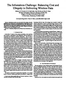
Figure 2. a) Ground truth vs. dead-reckoning vs. particle filtering. b) Error graph.
2. Background Certain devices focus on local hazard detection to provide obstacle-avoidance capabilities to users with VI [5, 6]. Most navigation systems, however, are able to locate the user and provide directions to a user-specified destination. Outdoor navigation systems [7, 8] typically use GPS for localizing the user. Indoor systems cannot use GPS signals, which are blocked by buildings, and alternative localization techniques have been developed: A) Dead-Reckoning techniques integrate measurements of the human’s motion. Accelerometers [9] and radar measurements [10] have been used for this purpose. Without any external reference, however, the error in dead-reckoning grows unbounded. B) Beacon-based approaches augment the physical space with identifiers. Such beacons could be retro-reflective digital signs detected by a camera [11], infrared [8] or ultrasound identifiers [12]. A popular solution involves RFID tags [13–15]. Nevertheless, locating identifiers may be hard, as beacons may require line of sight or close proximity to the human. Other beacons, such as wireless nodes [16–18], suffer from multi-path effects or interference. Another drawback is the significant time and cost spent installing and calibrating beacons. C) Sensor-based solutions employ sensors, such as cameras [19], that can detect preexisting features of indoor spaces, such as walls or doors. For instance, a multi-camera rig has been developed to estimate the 6 DOF pose of people with VI [20]. A different camera system matches physical objects with objects in a virtual representation of the space [21]. Nevertheless, cameras require good lighting conditions, and impose a computational cost prohibitive for portable devices. An alternative makes use of a 2D laser scanner [2, 22]. This method achieves 3D pose estimation by integrating data from an IMU unit, the laser scanner, and knowledge of the 3D structure of the space. While laser scanners can robustly detect low-level features, they are relatively expensive and heavy. The proposed approach is also a sensor-based solution. It employs the user as a sensor together with information from light-weight, affordable devices, such as a pedometer and a compass. These sensors are available on smart phones and it is interesting to study the feasibility of using such popular devices to (i) interact effectively with a user with VI; and (ii) run in real-time localization primitives given their limited resources. To achieve this objective under the minimalistic and noisy nature of the available sensors, this work utilizes probabilistic tools that have been shown effective in robotics and evaluates their efficiency for different forms of direction provision. Bayesian methods for localization work incrementally, where given the previous belief about the agent’s location, the new belief is computed using the latest displacement and sensor reading. An important issue is how to represent and store the belief distribution. One method is the Extended Kalman filter (EKF) [23, 24], which assumes normal distributions. While Kalman filters provide a compact representation and return the optimum estimate under certain assumptions, a normal distribution may not be a good model, especially for multi-modal distributions. An alternative is to use particle filters [25–30], which sample estimates of the agent’s state. Particle filters are able to represent multimodal distribution at the expense of increased computational cost. Multi-modal distributions arise often in the paper’s application, such as when a door is confirmed by the user, where the belief increases in front of all of the doors in the vicinity of the last estimate. Thus, particle filters appear an appropriate solution in terms of accuracy. This paper shows that it is also possible to achieve a sufficient real-time solution with a particle filter approach.
3. Methodology 3.1. High-level operation Tactile landmarks, such as doors, intersections or floor transitions, play an important role in the cognitive mapping of indoor spaces by users with VI [3, 4]. By incorporating the unique sensing capabilities of users with VI, the system aims to provide guidance in spaces for which the user does not have a prior cognitive map. The system assumes the availability of a 2D map with addressing information (room numbers) and landmark locations. Then, it follows these steps: 1. A user specifies a start and destination room number to travel to. 2. The system computes the shortest path using A* and finds landmarks along the path. 3. Directions are provided iteratively upon completion through the phone’s built-in speaker. The user presses a button on the phone after successfully executing each direction. 3.2. Direction Provision The type of directions significantly effects the efficiency and reliability of navigation. Reliability is high when the user is required to confirm the presence of every single landmark along a path but this is detrimental to efficiency. Conversely, when the system solely relies on odometry, users have a smaller cognitive load but a high chance of getting lost, due to the inherent propagation of errors associated with dead reckoning. To gain a better insight in these tradeoffs two different types of direction provisions were tested: • Landmark based directions, e.g., “move forward until you reach a hallway on your left ”. No distance to a landmark is provided. Directions were subdivided based on the maximum distance between landmarks: (a) 30ft, (b) 50ft and (c) unlimited. Wall following and door counting strategies were employed for the first 2 cases (i.e., “Follow the wall on your left until you reach the third door”). For the last case no wall following or door counting strategies were used for directions leading to a hallway. • Metric based directions, e.g., “Walk x steps until your reach a landmark on your left/right”. Within this approach the maximum distance between landmarks was also varied with 30ft, 50ft and unlimited. For example: “Walk 23 steps until you reach a door on your right” for the 30ft limit. Both types of instructions contain a second type of direction with an action on a landmark, for example, “Turn right into the hallway”.
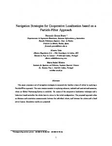
Figure 3. The map of the environment and the paths traversed during the experimental section.
3.3. Localization Consider a planar system moving among n static landmarks. The system is a human with VI, and the landmarks corresponds to tactile features of indoor spaces. Let ξ = (x, y, θ) denote the state of the system. The map m of the world is available and stores a function which returns whether each(x, y) is occupied by an obstacle or not. The map also stores the n landmarks present in the world. The landmarks belong to k different types {L1 , . . . , Lk }, such as doors, hallway intersections or floor transitions (most often k < n). Landmarks li in the same class Lj are indistinguishable to the human user. The data dT = (o(0:T ), u(0:T − 1)) available to the system up to time T are transitions u(0:T − 1) and observations o(0:T ). A transition ut = (uft , uθt ) at time t corresponds to a motion where the agent acquires the global orientation uθt and moves forward uft . This transition determines the kinematic transition model of the system: (1) (xt+1 , yt+1 , θt+1 ) = (xt + uft · cos(uθt ), yt + uft · sin(uθt ), uθt ) In this application the translation is measured from a pedometer and the orientation with a compass. An observation ojt of a landmark type Lj from state ξt = (xt , yt , θt ) implies: ∃ li ∈ Lj : ||(xt , yt ), (xi , y i )|| < Robs (2) The above observation model specifies that a user can sense a landmark type Lj in their vicinity, only if such a landmark li (xi , y i ) ∈ Lj is within a predefined observation distance Robs from the current coordinates of the system (xt , yt ). The objective is to be able to incrementally estimate the user’s state ξT at time T . The general Bayes filter computes a belief distribution BT = P (ξT |dT ) at time T over ξT given the data dT . The computation requires: a) an initialization B0 , b) a transition model P (ξ ′ |u, ξ), describing the probability that the user is at location ξ ′ if it was previously at ξ and transitioned by u, and c) the observation model P (o|ξ, m) describing the likelihood of observing o when the user is at ξ and given the map m. The map is assumed to be static and correct in this work. Then given a normalization factor Z η the belief distribution can be updated as follows: BT = η · P (oT |ξT , m)
P (ξT |uT −1 , ξT −1 ) · BT −1 · dξT −1
(3)
The computational cost of integrating over all states renders the explicit computation of Eq. 3 inefficient. Most online algorithms simplify the problem by approximating Eq. 1. This work follows a Particle Filter approximation. Particle Filter It is possible to represent BT through a set of P particles pi = (ξ i , wi ) (i ∈ [1, N ]). Each particle stores a state estimate ξ i together with a weight wi , representing the probability of ξ i being the true state. As the number of particles approaches infinity, the better the particle filter represents the belief distribution. In order to update the particle filter given a new transition and an observation, this work follows an approach similar to importance sampling [25]. At each time step T , given a particle population {p1T , . . . , pP T }, a transition uT and an observation oT +1 , the following steps are executed: A. For each particle piT = (ξTi , wTi ) i. Employ the transition model P (ξTi +1 |uT , ξTi ) to acquire: ξTi +1 . ii. Employ the observation model to compute the new weight wTi +1 = P (oT +1 |ξT +1 , m). B. Sample a new population of P particles given the weights wTi +1
Transition Model The approach collects all the sensor readings that have been produced by the sensors during the last time step: (i) orientations from the compass and (ii) step counts from the pedometer. Typically within a single time step (in the order of 150ms-300ms), the compass provides multiple orientation estimates. These are averaged to acquire uθt . The pedometer typically returns either zero or one step measured. This value has to be translated into a distance estimate. To compute the length of a step, the implementation employs a short training session for each user. During this session the user traverses a couple of paths between two landmarks with known distance. The pedometer computes the number of steps during the execution of these paths and the device estimates the average length of a step. Based on this estimate and the number of steps measured by the pedometer online, the approach constructs uft . Given uft and uθt , different levels of noise are added for the application of the transition model to each particle. The noise parameters for particle pi are drawn from a normal distribution: (i) (uft )i = N (uft , σf2 ) and (ii) (uθt )i = N (uθt , σθ2 ). The resulting values are used in Eq. 1 to acquire the new state ξTi +1 . The corresponding transition from ξTi to ξTi +1 is then checked on the map to compute whether it corresponds to a path that collides with obstacles. If it does, then the sampling of (uft )i and (uθt )i is repeated until either a collision free transition is found or a certain number of attempts has been tested. Observation Model There are two cases for computing the weights wTi +1 of the particles. If there was no landmark confirmation by the user during the last step, then all of the weights are equal to 1. If the user confirmed the presence of a landmark of type Lj , then the approach prunes particles not in the vicinity of such landmarks. In particular, for every pq the method finds all li so that ||(xqt , ytq ), (xi , y i )|| < Robs . If none of the li is of the type Lj , then wTi +1 = 0. Otherwise, the weight is inversely proportional to the distance ||(xqt , ytq ), (xi , y i )||, where li is the closest landmark of the correct type. Sampling The algorithm samples with higher probability particles with higher weights. It might happen, however, that all particles get a weight of 0 (“particle impoverishment”). This is why, the “Mixture MCL” method [26] samples a certain number of particles from the observation, while the “sensor resetting” approach [27] samples from the observation only when it deviates substantially from the previous distribution. The approach implemented by this work follows a similar idea. When all of the particles happen to get a weight of 0, which typically occurs when the user confirms a landmark li and the filter has failed to progress the particles to the vicinity of that landmark, then the particles are sampled from the observation as shown in the figure to the right. For each particle pqT , the method computes the landmark of the confirmed type that is closer to pqT . For the closest such landmark li , the line between pqT and li is computed. If there is line of sight between the particle and the landmark, then the new particle is sampled along the line segment [pqT , li ] and within the radius Robs , which represents the greatest distance from which a landmark can be sensed. The line segment is introduced in the computation so as to guarantee that the new particle will not cross into a room or into a different corridor.
4. Experiments Setup The system has been implemented as a Java application for the open-source Google Android smart phone (ver. 1.6). A map of a building’s floor on the campus of the University of Nevada, Reno was created in the Keyhole Markup Language (KML) and loaded to the application (Fig. 3). The map was manually augmented with the following landmarks: (i) 3 water coolers, (ii) 1 floor transition marked by a metal strip, (iii) 3 hallway intersections, (iv) 2 hallway turns and (v) 72 doors. Five different paths were defined along the corridors of the building. For each path, there are two alternatives for directions, with three levels of granularity each, as specified in Sec. 3.2. Overall, six different ways to provide directions were tested per path. The application communicated the directions using text to speech software. The user was able to confirm the completion of an instruction by pressing the tactile scroll button on the smart phone or could ask for a direction to be repeated by tapping on the phone’s screen. Participants Ten volunteers were involved in the experimental session. Users held the phone in their hand while holding a cane in their other (Figure 1). One of the volunteers was legally blind and assisted in the setup of the experiments. This individual pointed out landmarks, such as a metal strip on the floor, which sighted people typically ignore. Nine more volunteers were involved that were sighted users and who were blindfolded during the experiments. Typically, sighted users perform worse than people with VI when they navigate without visual cues. Some of the users had visited the building in the past and were aware of its structure, while others didn’t. This discrepancy did not seem to considerably influence the efficiency of users in reaching the desired destination. Each user executed ten traversals, which corresponded to two traversals per path using different types of directions. Ground Truth To measure the true position of the user, an observer was recording the user’s motion. This was achieved by placing markers on the floor every two meters. Every time the user was crossing a marker, the observer was recording the time on a second smart phone. To recreate the true path, the assumption was that the user moves with constant speed between markers. Thus, the resolution of the ground truth is two meters. Parameters The following table provides the parameters of the results presented here. A relatively high standard deviation for the orientation parameter in the transition model was chosen because of the unreliable nature of the compass. A very small number of particles (20) was used to achieve real-time performance, while being able to save output files at the same time. Recording the status of the application (e.g., saving all the measurements, landmark confirmations and the particle filter state) takes three times longer than the actual estimation by the particle filter. Thus, in a real application the particle filter can run with at least 3 times the number of particles. Number of Particles P
20
Landmark radius Robs
1 meter
Standard Deviation in Orientation σθ
30o
Standard Deviation in Forward Motion σf
0.2 meters
Maximum Number of Tries To Find a Collision Free Transition
5
Success Ratio of Direction Provision Table 1 provides the average distance between the destination and the actual position achieved by the user over all experiments of the same type. This table shows that most of the paths were completed successfully. In particular, in 84% of the experiments the distance between the desired destination and the achieved position was less than 2 meters, which is the resolution of the ground truth. In 92% of the experiments the error was less than 3.5 meters. It also turns out that landmark-based directions result in smaller errors and higher success ratios. Table 2 provides the average duration of a path until completion. The users were able to complete paths quicker when they were not asked to confirm a larger number of landmarks, which was the expected result (“No Max” case in direction provision). Distance from Destination
Path 1 (98.14m)
Path 2 (69.49m)
Path 3 (72.54m)
Path 4 (67.66m)
Path 5 (54.25m)
Landmark No Max
0.46
1.83
0
2.44
1.83
Landmark 9 Meters
0
1.22
0.46
2.19
1.83
Landmark 15 Meters
0.91
0.91
1.83
1.83
2.29
Metric No Max
2.74
0.61
0
2.29
1.83
Metric 9 Meters
3.05
2.74
1.22
0.91
1.22
Metric 15 Meters
4.57
0
0
2.74
1.83
Table 1. Average distance between destination and the user’s position upon completion (m) Path Duration
Path 1 (98.14m)
Path 2 (69.49m)
Path 3 (72.54m)
Path 4 (67.66m)
Path 5 (54.25m) 111.25
Landmark No Max
155.75
123.67
135.67
119.67
Landmark 9 Meters
201.33
177.00
212.00
192.50
138.75
Landmark 15 Meters
265.00
155.25
156.50
226.67
110.50
Metric No Max
136.25
180.00
137.50
129.50
108.50
Metric 9 Meters
242.67
252.75
173.67
219.00
169.00
Metric 15 Meters
264.00
173.67
247.00
180.00
147.33
Table 2. Average path duration (sec).
Localization Accuracy Tables 3 and 4 provide the errors for dead reckoning and the proposed particle filter based approach. In particular it specifies the average error in meters between the final true location of the user and the estimate by the corresponding technique. The estimate from the particle filter corresponds to the particle which was closer to the average state of all particles at the last iteration. It is important to note that in most cases there were particles closer to the true position than the “average” particle. The comparison between the two tables shows that the particle filter approach improves considerably over the result acquired just by integrating the sensor readings. The improvement ranges from a factor of 10 to a factor of 2 for different paths and direction provisions. This despite the very small number of particles employed by the approach. The important point, however, is the considerable effect that the direction provision process has on the efficiency of the particle filtering algorithm. The average error in meters in the final location for the “Landmark 9 meters” approach is approx. 9.5 meters, while it goes down to 2.1 meters for the “Landmark 15 meters” approach, which also appears to be the best solution to the problem. The errors were lower for paths that contained distinctive landmarks such as hallways (in the order of 1.2-2.5m) and considerably higher
for paths that corresponded to long straight line paths where all the landmarks were the same (doors). Figure 2 provides an error graph for a specific path/direction provision combination for dead reckoning and the particle filter approach. The expectation is that as the computational power of portable devices increases, it will be possible to run the same algorithm for a larger number of particles and thus further improve accuracy. Dead-Reckoning
Path 1 (98.14m)
Path 2 (69.49m)
Path 3 (72.54m)
Path 4 (67.66m)
Path 5 (54.25m) 13.79
Landmark No Max
20.79
25.53
10.83
9.82
Landmark 9 Meters
10.19
32.50
17.87
8.59
13.43
Landmark 15 Meters
26.81
26.89
16.29
13.12
8.89
Metric No Max
14.91
25.69
15.49
13.41
11.65
Metric 9 Meters
18.00
28.99
23.84
5.89
7.53
Metric 15 Meters
19.55
20.95
31.44
3.88
7.90
Table 3. Average error of dead reckoning in final location (m). Interactive Localization
Path 1 (98.14m)
Path 2 (69.49m)
Path 3 (72.54m)
Path 4 (67.66m)
Path 5 (54.25m) 5.31
Landmark No Max
18.80
15.51
1.32
1.14
Landmark 9 Meters
10.12
25.95
1.34
3.02
7.35
Landmark 15 Meters
5.47
4.02
3.03
3.63
2.33
Metric No Max
12.95
11.33
3.98
3.75
5.38
Metric 9 Meters
3.20
11.92
0.84
3.05
4.24
Metric 15 Meters
10.43
5.25
3.06
1.48
3.87
Table 4. Average error of the proposed interactive localization process (m).
Note that the errors in tables 1 and 4 are not comparable, since the first corresponds to how close the user reached the desired destination and the last two tables correspond to localization accuracy. The current method for guiding the user does not depend on the localization process and this explains why it is possible for the error in localization to be higher than the distance between the true user location and the desired one.
5. Discussion This paper presented a study on the feasibility of navigating a user with VI through an indoor environment using a minimalistic and interactive sensing approach achievable with a smart phone. The sensors used in the experiments are inexpensive and available on popular portable devices. Nevertheless, they are also highly erroneous. For instance, compass sensors, especially cheap ones, perform very poorly in indoor environments due to metal structures and electro-magnetic noise. This was also the case in the building were the experiments presented in this paper were executed. Despite this challenge, it was still possible to track a human user who does not have any visual feedback with sufficient accuracy through an interactive localization process. This line of research opens the door to exciting new applications for methods from robotics in the area of human-centered autonomous intelligent systems. For instance, minimalistic approaches could be employed to improve localization accuracy while
maintaining a low computational overhead (e.g., an Information Space approach). Similarly, it is interesting to investigate how to automatically plan alternative paths that lead along a larger number of landmarks or along more distinguishable landmarks, such as preferring a hallway confirmation over a door. Such planning under uncertainty tools may significantly boost chances of the user successfully arriving at the destination and the localization estimate being more accurate. Future user studies will aim towards involving a larger number of users with VI, who will navigate in more complex environments that involve a larger variety of landmarks. For instance, buildings with multiple floors that involve elevators and ramps. Furthermore, in the current system the next direction is provided manually based on the user’s confirmation of successfully executing the previous one. This feasibility study has shown that sufficiently accurate localization is achievable through such interaction, which may allow for automatic direction provision based on localization estimates. This could make navigation more efficient as the user does not have to engage in tasks such as door counting. The overall approach will combine manual (upon user’s confirmations) and automatic direction provision (based on localization estimates) to guide the user. 2D maps of an indoor environment, as used here, can be acquired from architectural blueprints. Nevertheless, it may be more useful to use richer types of representations. 3D virtual models can be employed to more accurately represent indoor environments with multiple levels and features like low ceilings, ramps, uneven floors and rails, which are impediments to navigation for users with VI. It is interesting to investigate how to extract landmarks such as doors or staircases automatically from the geometry of such models in order to utilize them in navigation and localization tools for individuals with VI. Similarly, it is also possible to make use of more realistic models of human motion [31] instead of the unicycle-like system employed in this work. References [1] S. Willis and S. Helal, “Rfid information grid for blind navigation and wayfinding,” in ISWC ’05: Proc. of the Ninth IEEE International Symposium on Wearable Computers. Washington, DC, USA: IEEE Computer Society, 2005, pp. 34–37. [2] J. A. Hesch, F. M. Mirzaei, G. L. Mariottini, and S. I. Roumeliotis, “A 3d pose estimator for the visually impaired,” in Proc. of the IEEE/RSJ Intern. Conference on Intelligent Robots and Systems (IROS), Oct. 11-15 2009, pp. 2716–2723. [3] A. A. Kalia, G. E. Legge, and N. A. Giudice, “Learning building layouts with non-geometric visual information: the effects of visual impairment and age,” Perception, vol. 37, no. 11, pp. 1677–99, 2008. [4] A. P. B Tsuji, G Lindgaard, “Landmarks for navigators who are visually impaired,” in Proceedings International Cartography Conference, 2005. [5] S. Shoval, J. Borenstein, and Y. Koren, “Auditory guidance with the navbelt - a computerized travel aid for the blind,” IEEE Transactions on Systems, Man and Cybernetics, vol. 28, no. 3, pp. 459–467, August 1998. [6] D. Yuan and R. Manduchi, “Dynamic environment exploration using a virtual white cane,” in Proc. of the IEEE Conf. on Computer Vision and Pattern Recognition, San Diego, CA, June 20-25 2005, pp. 243–249. [7] J. M. Loomis, R. G. Golledge, and R. L. Klatzky, “Navigation system for the blind: Auditory display modes and guidance,” Presence: Teleoper. Virtual Environ., vol. 7, no. 2, pp. 193–203, 1998. [8] D. A. Ross and B. B. Blasch, “Development of a wearable computer orientation system,” Personal Ubiquitous Comput., vol. 6, no. 1, pp. 49–63, 2002. [9] F. Cavallo, A. M. Sabatini, and V. Genovese, “A step towards gps/ins personal navigation systems: realtime assissment of gait by foot inertial sensing,” in Proc. of the IEEE/RSJ Int. Conf. on Intelligent Robots and Systems, Edmonton, Canada, August 2-6 2005, pp. 1187–1191.
[10] P. Van Dorp and C. A. Groen, F., “Human walking estimation with radar,” IEE Proceedings, Radar, Sonar and Navigation, vol. 150, no. 5, pp. 356–365, 2003. [11] B. Tjan, P. Beckmann, N. Giudice, and G. Legge, “Digital sign system for indoor wayfinding for the visually impaired,” in Proc. of the IEEE Conf. on Computer Vision and Pattern Recognition - Workshop on Computer Vision Applications for the Visually Impaired, San Diego, CA, June 20-25 2005. [12] L. Ran, S. Helal, and S. Moore, “Drishti: An integrated indoor/outdoor blind navigation system and service,” IEEE International Conference on Pervasive Computing and Communications, p. 23, 2004. [13] V. Kulyukin, C. Gharpure, J. Nicholson, and S. Pavithran, “Rfid in robot-assisted indoor navigation for the visually impaired,” in Proc. of the IEEE/RSJ Int. Conf. on Intelligent Robots and Systems, Sendai, Japan, Sept. 28-Oct.2 2004, pp. 1979–1984. [14] M. Bessho, S. Kobayashi, N. Koshizuka, and K. Sakamura, “Assisting mobility of the disabled using space-identifying ubiquitous infrastructure,” in Proc. of the 10th Int. ACM SIGACCESS Conf. on Computers and Accessibility (ASSETS). Halifax, Nova Scotia, Canada: ACM, 2008, pp. 283–284. [15] T. Amemiya, J. Yamashita, K. Hirota, and M. Hirose, “Virtual leading blocks for the deaf-blind: A realtime way-finder by verbal-nonverbal hybrid interface and high-density rfid tag space,” in Proc. of the IEEE Virtual Reality, Washington, DC, USA, 2004. [16] T. H. Riehle, P. Lichter, and N. A. Giudice, “An indoor navigation system to support the visually impaired,” in 30th Annual International Conference of the IEEE Conference on Engineering in Medicine and Biology Society (EMBS), Aug. 2008, pp. 4435–4438. [17] A. M. Ladd, K. E. Bekris, A. Rudys, G. Marceau, L. E. Kavraki, and D. S. Wallach, “Robotics-based location sensing using wireless ethernet,” in Eight ACM International Conference on Mobile Computing and Networking (MOBICOM 2002), ACM Press. Atlanta, GA: ACM Press, September 2002. [18] A. M. Ladd, K. E. Bekris, A. Rudys, L. E. Kavraki, and D. S. Wallach, “On the feasibility of using wireless ethernet for indoor localization,” IEEE Transactions on Robotics and Automation, vol. 20, no. 3, pp. 555–559, June 2004. [19] O. Koch and S. Teller, “Wide-area egomotion estimation from known 3d structure,” in Proc. of the IEEE Conf. on Computer Vision and Pattern Recognition, Minneapolis, MN, June 17-22 2007, pp. 1–8. [20] F. Dellaert and S. Tariq, “A multi-camera pose tracker for assisting the visually impaired,” in 1st IEEE Workshop on Computer Vision Applications for the Visually Impaired, June 20-25 2005. [21] A. Hub, J. Diepstraten, and T. Ertl, “Design and development of an indoor navigation and object identification system for the blind,” in Proc. of the 6th Int. ACM SIGACCESS Conf. on Computers and Accessibility (ASSETS). Atlanta, GA, USA: ACM, 2004, pp. 147–152. [22] J. A. Hesch and S. I. Roumeliotis, “An indoor localization aid for the visually impaired,” in Proc. of the IEEE International Conference on Robotics and Automation (ICRA), Roma, Italy, April 10-14 2007, pp. 3545–3551. [23] R. E. Kalman, “A new approach to linear filtering and prediction problems,” Transactions of the ASMEJournal of Basic Engineering, vol. 82, no. 35-45, 1960. [24] R. Smith, M. Self, and P. Cheeseman, Estimating Uncertain Spatial Relationships in Robotics. Springer Verlag, 1990. [25] N. J. Gordon, D. J. Salmond, and A. F. M. Smithm, “Novel approach to nonlinear/non-gaussian bayesian state estimation,” IEE Proceedings on Radar and Signal Processing, vol. 140, no. 2, pp. 107–113, 1993. [26] S. Thrun, D. Fox, W. Burgard, and F. Dellaert, “Robust monte carlo localization for mobile robots,” Artificial Intelligence, vol. 128, no. 1-2, pp. 99–141, 2000. [27] S. Lenser and M. Veloso, “Sensor resetting localization for poorly modelled mobile robots,” in Proc. of the IEEE Int. Conf. on Robotics and Automtion (ICRA), San Francisco, April 2000. [28] I. M. Rekleitis, “A particle filter tutorial for mobile robot localization,” Centre for Intelligent Machines, McGill Univrsity, Montreal, Quebec, Canada, Tech. Rep. TR-CIM-04-02, 2002. [29] S. M. Oh, S. Tariq, B. Walker, and F. Dellaert, “Map-based priors for localization,” in IEEE/RSJ International Conference on Intelligent Robots and Systems (IROS), 2004. [30] S. Thrun, W. Burgard, and D. Fox, Probabilistic Robotics. MIT Press, September 2005. [31] G. Arechavaleta, J.-P. Laumond, H. Hicheur, and A. Berthoz, “An optimality principle governing human walking,” in IEEE Transactions on Robotics, vol. 24, no. 1, 2008.