Proceedingsof FEDSM'98 1998ASMEFluidsEngineeringDivisionSummerMeeting June 2l-25, 1998,Washington,DC,USA
FEDSM9S-5042 VOIDFRACTIONMEASURMENT BENEATHA STATIONARY BBEAKINGWAVE TriciaA, WaniewskilChristopherE. Brennen,and FredricRaichlen Divisionol Engineering andAppliedScience California Instituteof Technology Pasadena, Calilornia91125 Email:
[email protected]
ABSTRACT Impcdance basedtechniques havebeenus€dro quantifyair entrainment by a stadonary breakingwaveat $e bow of a ship. The prcsentpaperdcscribes an impedancc ba!€dvoid fracrion m€t€rwhichwasdeveloped ro makemeasuremenb in ihis high speed, unsteady, multiphase llow.anddetailsof ils catibrarion are provided.In addition,air enrrainment datafrom ancxperimental simulalionof a bow waveare presented. The locar,ome averagedvoidfraclioowas mappedfbr flowcrosssectionsbenearh th€ plungingwavcjet,reveating thelocationof rhecloudsofbubbles fonnedby thalj€t impactingrh€ incomingwatcrsurface.Size distribution funclionslbr thebubbles withinthcbubbleclouds arc alsopresentcd. Theresulrsareconelared withrh€w described in Waniewskict al. (1997). NOMENCLATURE r4 IVFM measurement crossseclionat ar€a(n2) d Depth(m) F Froudonunberbasedordepth,F=U/.rEA s Gravilationalacccleration(r'l;) 1 Bubblechordlength(nn) X Bubblecountrate (cornrrlr) U Freestrearnvelocily (,,/r) r Streanwisecoordinare(.n) ), Crossstreamcoordinare(.-) z Verticalcoordinare(cn ) 'AddEss .il
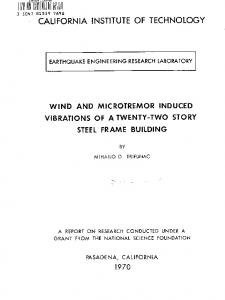
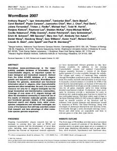
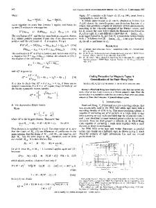
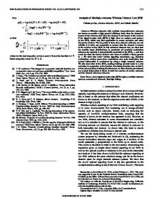
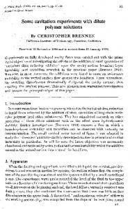
Figurel- PHoToGRAPHOF THE TESTSECTIONVIEWEDFROM U P S T F E A M=| € 1 3 . 4 " 0 , 0^ J 1 5 ' , U = 2 . 4 5 m / s , d = l I . 4 5 c n , ^ N o
Void fract'on (7o) Dibedral angle (degre€t O 0 wcdge halfansle (degrees) d
INTRODUCTION h flowsaroundships,a bea&ingbowwaveentrainsair as itsjet impinges continuousty onthefreesurface. Thercsuhing
corespondedc€to rhis author
Copyrighl@ 1998by ASME
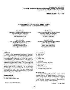
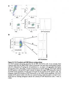
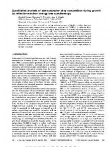
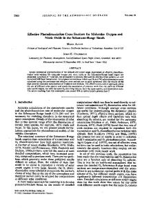
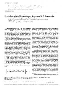
1.6rnm Fig!@3. CRoSS"SECTIONAL VIEWOF THElVFr\,| PROBE,NOTTo SCALE. Figur€2. HIGHSPEEDVIDEOLOOKING BENEATH THEFBEESURFACEAT BUBBLECLOUDSPASSINGBY THE T]P OF THE IVFM PBOBE, THEFLOWISFFOMBIGHTTOLEFTANDTHE PROBEISLO. CATED BENEATH THEll\,1PACTING BOWWAVEJEI 0 = 25o,O= 0o. U = 1 . 8 3 , n / s , d= 8 . 0 l c m ,A N DF = 2 . 0 6 .
air bubblespersistin the ship wakeaffecting its radarcrossseclion aswell asactingascavitationnucleiin theflowenteringthe shiphpropeller.In tbc presentinvestigation, theformadonofa bow wav€on a ship wassimulatedin thelaborarory usinga dcffecting plate in a supercriticalfr€e suface flow. Figure I shows theexperimental setup anddetailsarcgivenin Waniewski eral. (1997). Photographs showthattheair is entrained ospe.iodicbubble cloudsandanexampleis shownin Figure2.Thesebubbleclouds havca diameterof approximately5 cm andarecomprisedof bubbleswhich arcpackedtighter at the centerof thecloud thanat lhc cdgcs.In thc prcsentexperimentalconfiguration,thecloudsse€m to grow in sizc at a steadymte until they encounterrhe bortom and/oroppositewall ofthe flumefacility.Bubblesizc,vclocity, andvoid t-actionwere measur€dusing higb sp€edvideosandan impcdancebasedvoid ftaction meter(MM).
DESIGNOF IVFM Unsteady dynamic void fraction measurements by impedanccbasedlechniqu€shave beenconduct€dsuccesstully by many reserrcherssince the s€minal work of Cimorclli and Evanselisti(1969),Garard andLcdwidse(19?l), andJallouk et al (1979).TheseincludeBemicr(1982)andChansor(1988) anong others. The IVFM discussedherein is different sinceit doesnot measue the averagevoid fiaction over a measurement volumebut ratherdetectsbubblesaaa prnicularpoinrto define a local void fraction. The designdescrib€din the following sectionsis simple,low cost,hasa gooddynamicresponse, and is robustin high speedflow conditions,all rcquir€menlsfor the ship bow wavemeasulements.
Probe design Thc IVFM probewhich consistsof rwo concentricstainless steelelectrodes is basedon a designby Chanson(1988)andis shownin Fipre l. The outerannularclcclrodeis a s}ringeneedle; the innerelectrodeis a wire with a diameterof 0.6 mm, Epoxy lills thegapbetweenthetwo electrodesandinsulatesthem from eachother Also, rhe outerelectrodeis insularedfrom the waGrexceptfor a lengthof approximalely 0.5 mm from rhetip. The probe has a sharpenedtip to avoid 8ow separationand is mounledon a supportsystemdownstrcam of theprobe, Theprobe'ssmallsizeallowsit to respond to indivjdualbubbles.Experiments with largerprobesofthis styledidnotproduce desimblesignalto noiseratios.Parallelplatestyleprobestesred fo. usehadgrounding loopandvibrationproblems; theyalsoentained air in the separationzonesgeneratedby the plates. The probeis attrchedto a carriage,visible at the top of Fjgure I, whichtavels on precisionrailsmount€dto lhe top of the flumesidewalls.It canbe movedirl thecross-stream anddownstseamdirectionsby two servomotoN controllcd by a PC, Electronic design The electronicsassociatedwith the MM der€crssmall changesin the fluid impedanceof the waler immediately surroundingtheprobe.An oscillatoris usedto generate a sinusoidal voltagesignalof + 5V and500kHz which.afterpassing though a buffer, is appliedto the ioner electrodc.The outerelecrode is ground€d.Whena bubblepass€sthe plobe tip, the cunent flowing betweenthe two electrodesis reduced,and a cunent meteris usedto measurethis change.The ouiput is then low-passfilrercd with a cutotrof40 k}Iz anddemodulaterito provide a DC signal proportionalto the tocal void fraction. The resulting DC signal fiom theIVFM is sampledusinga dala acqujsitionsystemwith a datacollectionrate between2 kHz and20 kHz deDendinson rhe bubblevelod.y.
SINGLE BUBBLE TESTS Singlebubblelesrswere performedto deaerminerhe sensitivity of rheFobe to bubbleposition.The probewasmounted CopyflghrO 1998hy ASME
-1
gUBgtE TESTSETUP. Flgure4. H|GHSPEEOVTDEO OF STNGLE ONCETHE BUABLESDFTACHFBOMTHE TUBING,THEY TRAVEL UPWARoSWITHA VELOCITYOF0.27n /r, ANDIMPACTTHEpRoBE TIPAS AN OBLATESPHEROID SHOW!ATTHETOP.
il|l tims (s) Figurs6. TYPICAL IVFMSIGNALFBOMTHECALIBFATION EXPEF" IMENTS. A VOLTASE OF .1.2V OCCURS WHENNOBUBBLES ARE TOUCHING IHE PFOBETIP ANDEACHLABGENEGATIVE SPIKE @RRESPONDS TOANAIFBUBBLE PASSING BYTHEPROBE TIP, cationof the bubbleat impact.
CAUBRATION OFIVFM
0
0,1 ltmg(s)
0.2
Flgurc5, TYPICAL IVFMSIGNALFROMTHE STNGLE aUBBLE TESTS,EACHLABGENEGATIVE SPIKECORRESPONDS IO ANAIR BUBBLE II\,IPACTING THEPROBE TIP.
in a shall aquariumwith the tip pointing dowlward. A small ait pump was connect€dto a 1.66mm diameterslaiolesssteelrube installedseveralcentim€tersb€low the prcbe rip_ The air flow rate was adjustedso that singl€ bubbl€swere intemitt€ndy re, leasedfrom the stainlesssteeltube. The bubbleswerc ofuniform 5 trlm diameterjustbeforercleaseanddeformedaslhey tnvet€d upwardasshownin Figure 4. The high speedvid€o cameraand theIVFM dataacquisitionsyst€mw€reEigg€redsimultaneously. Figure 5 showsa typical signal. Corelarion of lhe imageswi& thesesignalsconfrm€d that a lege negativespike is prcduc€d each.ime a bubbleimpactsthe pmb€,atdough the spikeamplitudeandspikewidth wereshownto be s€nsi.iveio rhe taterallo-
A two phaseflow facility was used to calibmte the nrFM, This frcility included a vertical lucito pipe 10.16cm in diam€ter with an air injcctor located 1 m below the MM probe. The injector producedair bubbl€sof uniform size with a dianeter of roughly 5 mm, and lhe air flow ratc was rdjustable. Ttvo static prqssuretaps locat€d 1.1 m !pan, and approximatelye4ually spacedabovcand below the MM probe, were cornectedto all invenrd manometerwhosereadingwasusedto obtainthe steady statevoid ftaction, d. Higb spccdvideosof theseflows werealso obtained. A typical signd fron the MM correspondingto ci = 4.31% ftom the MM is shown in Figure 6. Bach of the spikesis well defined.The high sp€€dvideosconfirmedthat eachspikeconespotrdedwith the impact of a bubbleon the probetip. The MM signalswere post-processed using sofitwarc.Since the sampling mtewas2 kl{z, a fourth orderButterworthfilter witb a cutoff frequencyof I kgz (the Nyquist ftequency) was usedto eliminate any parts of the signal that had a non-physicalorigin. Fotwad and reveNefiltedng yielded z€ro"phasedistorion. To compensatefor any ddft of ihe I'FM electronics,the meannoiselevel wassubtract€dftom eechsignsl. Void fi:actionwas calculatedfiom .he condi.ionedsisnals. usins
de,.t)= :
lo
M(x,t).tt
(1)
Copyright@ 1998by ASME
20
81s t
U
p
-o
5 1 0 15 Manom€tor voidlraction%)
20
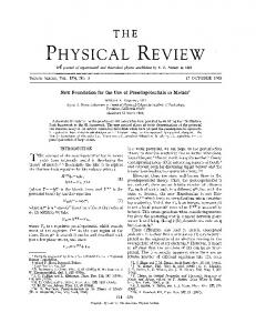
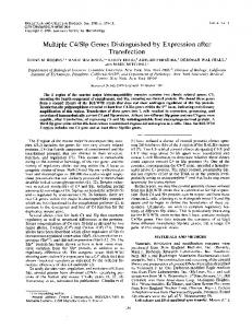
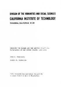
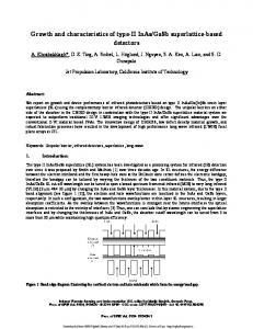
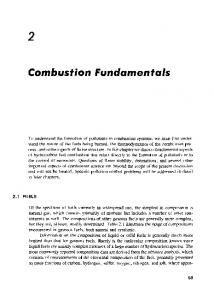
F|gIJIE 7, CALIBFATION CURVE FOFTHEIMPEDANCE BASED VOIO FFACTION IVETEBFROMTHETWOPHASEFLOWFACILITY. THE LINEAR CURVEFITFOFTHEDATA COARESPONOING TOfll = .0.75 VlSv=1.00x+0.32.
wherex is the measurementpoinl, and r is the integrationtime (Ishii, 1975).The valueof M(x,t)is cithcr0 or I depending on whetherthe signalexcecdeda chosenthresholdor not and rhercforc indicateswhetherthe probewas registeringrhe presenceof a bubble(or not). Similarprocedures havebccnusedby olher researchers usingconductivityprobesro measure void fmction. For exampl€,Teyssedouet al. (1988) repon€dgood agr€€menr betwee! void profles obtainedby their conductivity probe and an opticalprobe. The calibrationwas repeated on four differentdays,anda typicalcalibration curveis shownin Figure7. Thevoid fractions were estimatedusing threedifferent thresholds,and a rhreshold of -0.75Vwas shownto give the estimateclosestto the measuredvalue,especiallyat rhc lower void fractions.This threshold wasthenusedfor determiningvoid fraction in the simulatcdbow
Figure8. SCHEMATIC OIAGBAM OF THE FLOWFEATUBES W|TH A TYPICAIFLOWCROSSSECTIONINOICATEO. THE IVFMPROAE TRAVELS ALONGTHESECBOSSSECTIONS AND SA{VIPLES ARE 'X' FOBDIFFEB. TAKENAT POSITIONS SUCHAS THOSEIVARKED ENTDEPTHS.
0
I'r
;:-1
9_2
0.4
ilrillil 0.6
ume(s)
0.8
EXPERIMENTAL RESULTS
Figurs9. TYPICAL SIGNAL FBOi,,ITHE IVFMLOCAIED SEVEBAL cm BENEAII] rHE BoWWAVEJE\ | O = 260,q = 0o,U = 2.39n / s, d= 6.47.rn,ANDF= 3.00.USING THECALIBFATION CUBVE, THE TIMEAVER GEDVO|D FFACTION, d- 6.57o.
For measurements in the simulatedbow wave,theprobewas rnountedon the cariage as shown in Figure l. Sampleswerc takenat differcnt cross-sectionsin the impact line r€gion of the flow as illustratedin Figure 8. A typical signalfron the MM locateddirecdy beneathlhe impacting bow wavejet is shownin Figure9. Tlle l\TM signatsweresampledat 20kHz, thr€etimes for eachlocation. Simultaneoushigh speedvideo (5m fps) was taken with the field of view jlluminat€d by a stroboscopctrig, geredby the camen. The signalswere caretu y comparedwith thehigh specdvideoimages,andit wasfoundthalindividual bubbleswithin thebubblecloudproducedspikesastheyimpactedthe
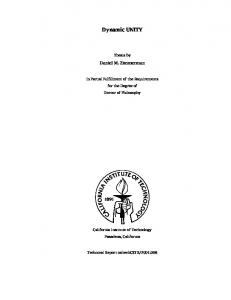
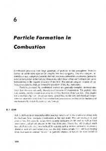
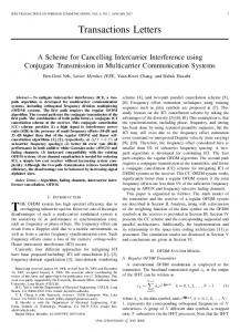
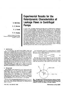
Fobe. The sigmls were then processedasdescribedin the precedingsectionto obtain the local, time-averagedvoid fiaction, and the calibmtion shownin Figure 7 for thr = -0.75 V was appli€d. Example.s oftime averagedvoid ftaction mappingsin theimpactregion of the plungingwavejet are shownin Figure 10. For eachlieure, lhe leading€dgeof the defl€ctingplate is locaredal (.r,r): (0,0) andtheupsrean ftee sudaceis locatedat z = 0. on avsage, the smnplinggri& for the cmsssectioncontained20 10-
Copyrighl@ 1998by ASME
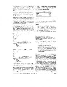
cations.Becausethe free surfaccis unsteady,it wasnor possible to estimalevoid ftactions at locationsabovez = I cm without the free surfacedipping below rh€probe,or the Fobe €nbaining arr liom abovethe free surface_ These figures confirm seveml observationsfrom rhe high speedvideo. Firsr, the bubble ctouds are shown to be roughty sphericalin shapeand grow as they convectdownstrean. Second, the greatervoid fractions at the centerof rhc cloud suppon the observationthat the bubblesarc more tightly packedat the cloudcenterthanat theedges. Thesevoidfractionmappings wi tl beuscdto estimatethe rateof air enllainmentby the wavefor dif ferentflow conditions. Bubblechordswerccalculaledby mulriplyingrhe individ, ualspikewidlhsfromtheI\TM signalsby themeannowvetocity (for verysmallbubblesthischordwouldbectosero thebubbledianeter).ThentheMM signalswereusedro producebub, blechorddistributions for thebubbleswhichcomprise thebubbte clouds.Figure11includesdistriburions for bubbleclouds localed at (hecross-section sbownin Figureloe. Most bubblechords w€r€1 -+ 7 mm (consistent wilh high speedvideoobservarions ofthe bubbles),andthe numberof thesebubblcsincrease from theedgeto thecenterofrhecloudandfromrhcbortomto rheroD ofthe cloud.ln addilion.larger pockersofaircxisl in rhecenrer of thecloudnearthe freesurface,givingriseto lhc larSerbubblechordsregistered. Thc largerpockersofair do norpersistin theclouds;theyareeitherbrokenup intosmallerbubbl€sby the turbulentffoworrise to rheliee surface. Thecenterofthe cloud,or theregionwith grcarest void fraction,waslocat€ddirectlyben€athrheimpactingplungingwave jet, Thescdistribuliondatawerelimiredby thc deprhof warer in the llume;distriburions ar depthsgreaterrhan? = -4 cm arc alTect€d by the bouom.Forthis reason,thedistribution daraarc confinedto locationsnearerto the fr€esurfaceandprovide informationon theinitialstagesofair enrrainment.
DtscusstoN Theprccccdingsectionpresentsrherime averagedvoid fractionsandbubbledisrdbulions; however, srudyofrheflucruarions in voidfractionareequallyimponanrespecially in undersranding the air cntrainmentprocessfor rhis type of wav€. Wani€wski€r 41.(1997)described surfacedisturbances on theplungingfaceof thc bow waveas"almostequallyspac€dsrriations"and'the edg€ ollhe breakingwavcis very roughandappearsalmostro bc comprisedof individualjets". Funhermorqitwas'tuspecred thatrhe periodicilyofthebubblecloudsis rclatcdto rheperiodicityofthe observedsurfaceincgularities". This hypothesiswill be investigatedthroughanalysisofrhe unsready componenr in thc void fractionmeasurernents. ln pariicular,recentsrudyof thse disturbanccsusingspecialflushmountedgagesprovidingwatersurface time historiesshowcdthat indeedthey convectdownsrrem with a parlicularwavelength,andit may be possibleto correlarethese
signals to those taken by the IVFM.
coNcLustoNs A simple impedancebasedvoid fraction neter with a dynamic responseof40 kHz war designedto quantify the air cnrained by a brcakingwave. SignalsFoduced by the inslrument trere interpretedusing high speedvideo images. A specialtwo phaseflow facility wasusedto calibratethe inskument,and it hasbeenusedto successtullydeterminethe local, time avcraged void ftactionassociated with air entrainedin an experimentally simulatedbow wave. Void fraction mappingsbeneaththe plunging wavejetshowthepathofthe bubbleclouds,andthenbubble chorddistributions havealsobeenneasured.
ACKNOWLEDGMENT The authors\lish to acknowledgeDr. StevenCeccio for $sistancein developingtbe MM electronics, Hai Vu fbr assistancein developingthe electronicsand the MM probe, Dr SudiploSur for assistancc with signalprocessing, and Dr. RobenoZenit for assistance with the two phaseflow testfacility. They arc also grateful for the suppon of the Ofnce of Naval Research undergrantnumbcrN00014-94-l-1210.
REFERENCES Bernier,R.,"UDsteady TtvoPhaseFlowInslrumcntation and Measurement", Ph.D.thesis,Divisionof Engineering and AppliedScience, Calilbrnialnstiautc of Technology, | 982. Borctto, F. and Lahey, R.T., "An Exp€rimentalStudy on Air Carry Under Due to a Plunging Liquid Jet", Journal of MultiDhase Flow, 19, 1993,281-294. ----aharffi;-----EAir Bubble Enlrajnmcnl in Free SurfmeTurbulen!Flows, DepaflmcntoI Civil Engineering at theUniversityofQucensland. ReportCH46/95,1995. Chanson,H. and Cummings,PD., 'Modeling Air Entrainmentin PlungingBreakers",IntemationalSymposiumon Waves-Physical-Numedcal Modelins,vancouver1994. Chanson, H., "A Studyof Air EntraitmentandAerationDc, viceson a SpillwayModel",PhDtbesjs,Ret 88-8,Dept.ofCivil Engrg.,Univ.ofCanterbury, New Z€aland,1988. Cimorell'. L. and Evangelisti,R., "ExperimentalDelerminationof fie Slip Ratio in a Venical Boiling Channel Under AdiabaticConditionsat AtrnosphericPressure", lntemarionalJoumalof Heat andMassTransfer, 12. 1969, 713,'t26. Cipriano, R.J. aDd Blanchard. D.C., "Bubble and Aerosol SpectraProducedby a l-aboratory Brealjng Wave", Joumalof Geophysical Research, 86, 198I , 8085 8092. Carrard,G. and Irdwidge, T.J., "Measurcrnontof Slip Distorliotr and AverageVoid Fraction in an Air Watcr Mixture",
Copyright@ 1998by ASME
v 1-----
6--
(a) r = 73.4.ri PLUNoINGwAvE JEI IMPACTSAT, - 63.r,
(b) r = EI-0.r!:PLUNCING VAVE ,ET IMPACIS AT r ! 65.n.
(c) r = 9l.2da; ?LUNGINC WA\'E JET MPACTS AT y F 69(a,
(d) r = 70,8.Di PLUNGINO WAVE JET TMPACTSAT , ! 56c2.
(.) r = 75.9.2'fLUNCING WAVE JET IMPACTSAT , * 60cD.
(0 r = E4.2cri PLUNGINGWAVE ,ET MPACTSATy E 6kr,
FIgUrc10, LOCAL,TIMEAVEFIAGED VOIOFFACT]ON FORTHBEEDIFFEBEI{T FLOWCBOSSSECTIONS ASVIEWEDFFoI\,tDoWNSTFEAM BENEATH THEBREAKING WAVE. FoB (a),(b),AND(c),e = 26',4 = 0", U = 2.48m/s,d= 7.89cm,ANoF =2.82. FOR(d),ls),ANDo 6 =26',+= 0",U =2.39n/+d = 6.47cn,ANOF= 3.00.TENEOUAT.LY SPAoED coNIoURLEVEISBETWEEN votD FBACTtoNs oF t% = 1%ONTHEOUTER AND1O% ARESHOWN, WTHVOIDFRACTION EDGEOFTHEBUAALE CLOUD, Australia Atomic Energy ResearchEsrablishmeot,1971,Lucas Heights,Sutherland, N,S.W Ishii, M., Thermo-FluidDynamicTheory ofTlvo, Phase Flow.Eyrolles,Par@IJallouk, PA., Iravell, W.H-, Shahrokhi,F., and J.E. Hardy, 'Advanced Instrumentationfor R€flood Srudies", Proc. of the U.S. Nuclear RegulatoryCommission,R€vi€w croup Meeting on Two PhaseRow Instrumentation,March 1979, Troy N.Y NUREG/CP.OOO6). Lamane, E. andMelville. WK., "Air EntsainmentandDis, sipanonin BreakingWaves",Natue, 35I , I 99 I , 469-472. Loewen,M.R., O'Dor M.A., and Skafel,M.C.,'Tubbles Entrained by Mechanicilly ceneraredBrcaking Wav€s", Jouflul of GeophysicalResearch , l0l , 1996,20759-2U69. Teyssedou, A., Tapucu, A., and I-orrie, M, 'Tmpedanceprobe to measure local void fracrion profiles",
Reviewof Scienrific Iosrrumenrs, 59(4),1988,631-638. Waniewski, T.A.,Brennen,C.E.,andRaichlen,F., "BxperimentalSimulationof a Bow Wave",hoc. ASMEFluidsEngi n€rriry DivisionSummerMerring,Synposjumon cas-Liquid TwoPhas€Flows,199?.
CopyrightO 1998by ASME
20
15
I E
2
2 5
0
0
1
0 2 0 3 l, bubblechod lenglh
0
0
(r), =75.9cn,t=66.6cn
1
0 2 0 3 I, bubbl€chordlenglh
0
(b)t =75.9cn,t=63.5.n
20
15
E =10 2
-0
r0
20
I, bubbls chod lenglh
30
(.Jt =75.9cay=@scn RgUT€11, BUBBLECHORDDISTRIBUTIONS FROMBUBBLECLOUDSOBSEBVEO BENEAIHTHE BREAKINGWAVE.EACH SUBFIGUBE PBESENTS DISTBIBUI|ONS FOBFOUFD|FFERENT DEqHS z: _lcm, z= 2cm,z= _3em. dn z= _4cm. THE FLOWCONDTTTONS ARETHESAI\,IE AS THOSEFORFIGUFElod.gJ.
Copyright @ 1998by ASME