This research paper discusses the development of a fiber composite fabrication ... tectural applications with the main focus on the geometrical framework based ...
FIBER COMPOSITE FABRICATION
Marco Corazza Viral Doshi Axel Körner Mehnaj Tabassum AA School of Architecture
EXPERIMENTAL METHODS OF ARCHITECTURAL APPLICATIONS
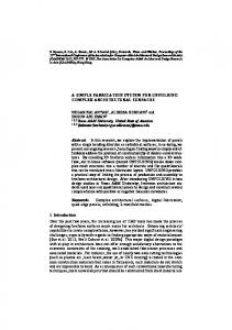
1 Sandwich Core Stresses–Comparison of core thickness to relative stiffness
ABSTRACT This research paper discusses the development of a fiber composite fabrication method for architectural applications with the main focus on the geometrical framework based on sandwich materials. The resultant geometrical articulations will be based on the inherent bending behavior of the chosen core material, thermoplastic foam, to overcome the need for extensive formwork. To gain control of the bending curvatures, several material manipulation strategies were investigated from differentiated distribution logics found in natural systems.
During the Master Thesis in the Emergent Technologies and Design program at the Architectural Association, the authors developed a design proposal for a typology that can be used as a test application for structural optimization, where environmental forces from wind and flood pressure acted as drivers for geometrical articulation. Studies centered on physical exploration of material limitations in terms of possible curvature and material computation, along with digital analysis of structural performance under extreme environmental conditions and feasibility within the proposed material system. Translation between physical and digital models was crucial throughout the process.
661
INTRODUCTION Architectural systems often rely on the agglomeration of components to create large constructions. The integration of fiber
of an evolutionary process, leading to robust and well-adapted morphology. The organization of fibers within a single structure is optimized for performance based on different criteria.
composite materials into building systems offers the possibility of complex integration of different performative requirements into
MATERIAL SCIENCE
one coherent system. Intelligent material distribution and variation
The term “composite material” describes a natural or man-made
can react on structural, environmental and spatial demands, as observed within natural systems (Greenberg and Körner 2014).
combination of at least two different materials, where the intent is to overcome the weak points associated in the individual materials by combining those with contrasting advantages (Gordon 1968).
Efficiency exists in composite materials in that individual materials with differing mechanical properties are tied together to strengthen each other. Where fibers are resistant in tension but lack compression capability, a resin matrix can be applied for the com-
A common natural example of a fiber composite material is wood, where strong cellulose fibers are embedded within a matrix of lignin cells. Under mechanical loads the cellulose fibers take the tensile forces while the lignin matrix carries the compression force.
posite to perform in both directions, thus creating new structural capabilities to test at an architectural scale.
Modern technical fiber composites can be seen as an artificial imitation of wood where strong fibers, such as carbon or glass, are
Although fiber composites are currently mainly used in high-end industries, especially aerospace and naval industries, where they are critical in achieving necessary high-strength to low-weight ratios, prevailing research from various architecture institutes is concerned with
embedded in a comparatively soft polymer resin. The mechanical properties of the chosen materials are critical, since the combination of both should not limit the properties of the individual materials (Knippers et al. 2011).
the integration of fiber composites into architectural systems, especially the ICD and ITKE research pavilions 2013 and 2014 in Stuttgart.
SANDWICH PANELS Efficient use of fiber composites results in low thickness of lami-
Research focuses on the usage of industrial robots to enable the pre-
nates and thus lacks stiffness. To counter this, an introduction of
cise application of fibers, where current production methods in naval
core materials can increase structural depth (Figure 1). High strength
and aerospace industries (North Sails, TU Delft) investigate the use of
skins made of fiber reinforced polymers are layered on either side
complex adjustable mold systems on which fiber composites can be
of a core, where the core material has to be able to take the shear
applied. Alternatively, the following paper explores a comparatively low-
loads between the outer skins (Knippers et al. 2011 and Gurit 2003).
tech fabrication where the bending behavior of structurally necessary core materials is used to generate form without extensive formwork. The link between structural performance and geometrical framework
APPLICATIONS IN ARCHITECTURE
given by the core material provides the opportunity to develop com-
For lightweight structures fiber reinforced composite materials of-
plex geometries following predefined structural and morphological
fer large potentials specifically due to their high strength to weight
requirements related for use within extreme environmental conditions.
ratio. Material properties can be adjusted for mechanical and aesthetic demands through lamination and additives. Therefore diverse design parameters in terms of form (structural and aes-
DOMAIN NATURAL SYSTEMS
thetic) and surface properties (such as transparency and, the inte-
Biological fiber composite materials are composed of just four
gration of functional components) are technically feasible (Knippers
different fibers in complex arrangements of highly specified distribution. Scaling from cells to whole organisms, the material distribution creates robustness, redundancy strength and adaptivity in
et al. 2011). The low thermal conductivity makes composite materi-
als suitable for use as structural elements and building envelopes. The resistance to aggressive media offers interesting fields for
higher-level system function.
application, such as offshore and coastal regions.
Biological closed shell structures made of continuous surfaces,
MATERIAL SYSTEM AMBITION
such as lobster (Stirn 2012) and turtle shells (Wyneken 2008) exhibit
Manufacturing methods play an important role in determining the
differentiated and specified properties due to varying material
strength and stiffness of composite structures. Most techniques
distribution. The global geometrical formulation is the product
use a mold to create different geometries resulting in the creation
DATA AGENCY
ACADIA 2014 DESIGN AGENCY
662
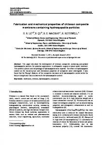
2 Adjustable Rod System–Forming of
individual panels using adjustable rods as guides
3 Adjustable Rod System Results–Panels
formed on the adjustable rod system created an uneven edge once connected
of extrinsic customized formworks. Therefore the research path investigated the development of a fabrication process utilizing the geometrical possibilities of core materials. This allows for the core to not only act as formwork, but also become a structural member for the generated composite.
The material research and the study of fiber composite applications lead to shell structures (Knippers et al. 2011, Nerdinger and Otto 2005 and Beukers and van Hinte 2005). Shells make use of their
geometrical properties to achieve structural efficiency, especially in cases of aerospace and naval industry, to respond to fluid dynamic demands. The possibility to create complex geometries while keeping the amount of used material comparatively low, make fiber composites efficient for lightweight structures. Although the industry has become one of the most technically advanced, fiber composites are still rare as building scale structural applications.
In terms of fabrication, high technology production methods were kept to a minimum to concentrate on hand crafted production (Eckold, G. 1994). This will make the material system more applicable to broader manufacturing fields.
RESEARCH DEVELOPMENT MATERIAL Based on price and availability, glass fiber would suit as the primary fiber supplying the structural advantage of woven reinforcement but at a fraction of the cost of the carbon equivalent Carbon fiber would be used as reinforcement only where necessary to reinforce areas of extreme forces. Glass fiber fabric was selected due to its economic advantage and ease of fabrication, where the textile easily achieved the double curvatures onto which it was.
663 CORAZZA, ET AL.
FIBER COMPOSITE FABRICATION
4 Chair Panels–Forming process of the panels included formwork
CORE MATERIAL A secondary material was necessary which could become an intrinsic part of the geometrical formwork as base material into which the glass fiber and resin could be directly applied.
Closed cell PVC foam is a lightweight rigid material that exhibits a Young’s modulus transformation at 120°C. With a reduced E-Modulus in the heated condition (similar to rubber) the foam can be molded into different shapes. Once cooled, it returns to its original stiffness while keeping the desired shape.
FABRICATION DEVELOPMENT The first formwork system was developed using adjustable metals rods between two wooden plates. By arrangement of the
5 Branchair Prototype–Forming process of thermoplastic foam panels and resin reinforcement for the chair model
rods, panels could be formed by pressing the heated foam onto the guides (Figure 2).
This system had issues in achieving a continuous surface where after forming two panels, the necessary edge continuity was not
The research continued to explore the geometrical possibilities
achieved (Figure 3). An alternate system was needed to ensure
of edge profiles made of the same thermoplastic foam as the
smooth transitions and efficient force flow between panels.
panels. Each panel would be offset to create positive and negative lips, generating an interlocking system to connect panels.
By forming different panels with the use of wooden edge profiles, tested in the prototype “Branchair” (Figure 4), (Figure 5), it was
BENDING PARAMETERIZATION
possible to achieve edge continuity, although the introduction of
In order to control the material limits of the foam and design the
extrinsic formwork was contradictory to the intended research.
global geometry it was necessary to parameterize the bending
Furthermore, in full-scale architectural applications the 10mm
behavior of the foam edge profiles. Due to time limitations during
thickness of single foam panels would not be sufficient to with-
our dissertation, the bending behavior was simulated with Strand7,
stand the external forces. Instead, edge profiles could be incorpo-
a finite element analyses (FEA) program. For further curvature
rated into the composite by acting as a framework onto which the
control, material removal through cutting patterns in different den-
panels are formed and creating the necessary structural depth.
sities was applied onto 10cm by 100cm foam strips.
DATA AGENCY
ACADIA 2014 DESIGN AGENCY
664
redrawing of the curves based on those parameters with B-spline curves of degree three, with four control points. To create this curve the endpoints are copied in the directions of the tangent vectors. The lengths of those vectors are dependent on rest length and pattern distribution.
6 Pattern Distribution–Varying cut pattern tests on the edge panels to show apex shifts.
Since for the equally distributed pattern the tangent vectors at the end points are axisymmetric to the center axis, it was possible to calculate a value for the maximum amplification of the tangent vectors (Figure 7). Therefore the length of the vectors in this case can be calculated with: 1/3 * rest length * c, with c=1.62. For the steps between rest length 80 per cent and 100 per cent the factor c has to be remapped between 1.00 and 1.62 according to the rest length.
The next step examined the relation to the pattern shift depending 7 Bending Parameterization–Calculations of the bending curve using tangent vectors
on the variable v. The curve for the pattern shift 80-20 per cent could be redrawn with the following two equations for amplification of tangent vectors: at point A: v*2/3*rest length*c and at point B:
ELASTIC MODULUS OF HEATED FOAM The E-modulus of the heated foam was calculated through a loading experiment to compute the material behavior. A strip of thermoplastic foam was centrally loaded and measured for its deformation. The calculations showed that the e-modulus of ther-
(1-v) 2/3*rest length*c with v=0.85. For the steps between the distribution of 50-50 per cent and 80-20 per cent the value of v varies between 0.5 and 0.85. Based on those values an approximation of all possible bending curvatures within this range is possible.
moplastic foam of 16.74 MPa was reduced to 11.4 MPa through
GEOMETRIES AND CURVATURE LIMITS
heating. Further finite FEA on thermoplastic foam were conducted
By adjusting the pattern and twist of the bent edge profiles it is
with this reduced value.
possible to generate surfaces of different synclastic and anticlastic curvatures. Allowing a linear movement of 20 per cent of the
CURVATURE PARAMETERIZATION
initial length, it is possible to generate an angle of 90°.
To parameterize the bending behavior of the edge profiles, different slotting pattern distributions were simulated in Strand seven to evaluate the apex shift of bending curvatures (Figure 6). Starting with an equal distribution of twenty slots in a strip of 1m length, the pattern distribution was shifted in increments of 10 per cent in one direction of the strip, resulting in slotting distributions of 5050 per cent, 60-40 per cent, 70-30 per cent and 80-20 per cent, the
Due to the material properties of the thermoplastic foam, curvatures in one direction cannot exhibit a lower radius than 10 cm. With this bending, it is possible to control the deformation and the spring back after the thermoforming process. To test the limitations of double curved panels, a series of physical experiments were conducted to analyze the maximum achievable double curvature.
maximum density shift we could archive, based on slotting width of 3 mm and 5 mm depth in the CNC milling machine.
Although it was not possible to fully explore these limits, single panels of 40cm by 40cm with principle curvature in radius of 40cm
To evaluate the different patterns, one side of the strip was moved towards the other end by increments of 5 per cent of the initial length.
in one direction and 50cm in the perpendicular direction, synclastic and anticlastic, were achieved. In this range we set the curvature limits for further experiments. Later, these limits were integrated in the panelization algorithm to test each panel in terms of their feasibility. To analyze if a certain panel is within the possible curvature
For the curvature parameterization the dependence between
range, the principal curvatures are measured on a grid of points
rest length, pattern distribution and the tangent vectors at the
on the surface and evaluated on two criteria (curvature values are
end points of the test pieces were analyzed. Doing so allowed
based on the unit meter). The panel cannot be produced:
665 CORAZZA, ET AL.
FIBER COMPOSITE FABRICATION
1. If the absolute value of min. or max. principal curvature exceeds the limit of ten. 2. If both absolute values of min. and max. principal curvatures are higher than 0.2 and the absolute value of Gaussian curvature 7.5 (the assumed limit derived from our physical tests).
CASE STUDY–CYCLONE SHELTER Since glass and carbon fiber in combination with epoxy resin are suitable for applications in marine environments, the research application focused on a new building morphology to be situated in an environment that continuously deals with flooding (Figure 8).
8 Cyclone Shelter Typologies–Architectural application as proposed through geometry, environmental conditions and material limit studies
The principle geometry was derived from a series of digital experiments of single elements and aggregation to reduce the surface pressure while creating the highest possible reduction in flood flow velocity (Corazza and Körner 2013, Doshi and Tabassum 2014). Fabrication and material behavior became the primary drivers for geometry exploration along with environmental pressures, where development of a closed shell structure was pursued. The resulting initial geometry was then subject to a genetic algorithm to optimize the shell in terms of structural efficiency based on high wind and water pressures (Figure 9). Although the structural aspect was the main focus, the multi-parameter optimization process also took into account design aspects in terms of usable space and feasibility within the material system.
The parameters themselves are based on structural constraints (floor spans) and spatial limitations (floor to ceiling heights). In optimization of the structural performance, the goal of surface manipulation was to minimize displacement under load conditions based on the movement of control points. The initial shell was
9 Initial Geometry Curvature Tests–Geometries analyzed in CFD to create closed shell elements
made of 4.0 cm foam core with 0.5 cm of glass fiber in epoxy matrix with a fiber-resin volume ratio of 50-50.
In order to optimize a building morphology to wind and water
The surface was broken down into domains to establish the
pressures, it was necessary to develop a way to transfer sur-
effects from the respective forces. The core, roof, edge and top
face pressures from the CFD analysis into Karamba (FEA for
portions experience wind pressure while the bottom wall portion
Grasshopper). This translation is based on a catalogue of possible
is subject to water flow. The process of parameterization involved
geometries tested in Autodesk CFD.
each domain being analyzed through a series of points, from which the normal vectors were measured against the applied flow
Experiments showed a relationship between pressure and angle between surface normals and the flow direction. In addition to this relationship, the global geometry and the gradient of curvature
direction. Calculating the angles of each individual during the optimization, as well as determining the respective pressure domain achieved an approximation of the acting forces.
changes (from positive to negative Gaussian curvatures) influence the pressure distribution on the surface (Figure 10), resulting in dif-
To map the value onto the surface the algorithm divides the global
ferent pressure values for the same angle between flow direction
geometry into a dense mesh of evaluation points. These points
and surface normal.
are determined based on their location in convex and concave
DATA AGENCY
ACADIA 2014 DESIGN AGENCY
666
10 CFD Pressure Mapping–Surface pressures analyzed on different closed shell structure curvatures.
11 Fittest Typologies–Optimization process of the extracted shell typologies
areas in different domains, where the angle between the surface
into point loads on the mesh for the FEA analysis with Karamba,
normal on each point and the flow direction is evaluated. The last
used for geometrical and structural optimization of the global
step maps a force onto the points. If the point is within the pure
geometry. This approach to transfer the pressure values from
convex shape, there is one pressure value for each angle. In areas
the CFD program into Grasshopper doesn’t supply 100 per cent
of curvature change from convex to concave there is more than
accurate values of forces acting on the surface, as it is an approxi-
one possible pressure value. To find the right value, an interpolat-
mation. The areas of negative and positive pressures are correctly
ed curve is generated along the evaluation points in the direction
evaluated and tendency of pressure distribution follows the values
of the flow and a second curve is mapped based in the curvature
based on CFD simulation.
graph of the first. Intersections of those curves mark transitions from concave to convex and back again. All points along those
Once the algorithm produces the shell surface, it is tested to
curves are stored again in domains based on their location along
check whether it falls within curvature limitations. The algorithm
the surface in concave and convex areas. Thus for each point in
evaluates the principle and Gaussian curvature for each panel
each sub-domain, one pressure value is extracted and translated
against the extracted criteria and contains a value which indicates
667 CORAZZA, ET AL.
FIBER COMPOSITE FABRICATION
if the surface is possible or not. Individuals who exceed the curvature limitations are disabled from progressing in the optimization process. Twelve individuals were selected based on differential weighting, and tested again in CFD to refine the surface pressures. After a second ranking, one individual was taken for further development (Figure 11).
PANELIZATION The next step in the development was the panelization of the outer shell and defining openings. An algorithm was developed to translate a given initial reference surface as close as possible to the material system. This includes panel subdivision, panel geometry adjustment based on material behavior and evaluation of
12 Panelization Process–Evaluation of the typology takes into account material curvature limits and feasibility
panel generation achievability within the system.
The primary subdivision into panels follows geodesic curves. For each point along the curve, the plane perpendicular to the curve includes the normal vector of the surface on this point. Therefore all edge profiles are planar curves, which can be unrolled into straight strips necessary for the controlled bending process(Pottmann et al. 2007 and Pottmann 2013) (Figure 12).
The algorithm evaluates intersection points of geodesic curves in U and V directions. Polylines are generated for each curve based
13 Topological Analysis–Openings were determined based on principal stress on the panels
on intersection points and the tangent vectors of the geodesics are evaluated. By comparing the angles between the vectors and the length of the line segments to the respective curve segments, it is possible to calculate the bending curve based on pattern distribution for each segment. A reference angle is calculated to determine both angles between vectors and line segments. Combined with the length of the segment, this information is used to determine the pattern distribution and the corresponding translation vectors necessary to create control points for the edge profiles. The actual panels are built by an edge surface through adjacent profiles.
OPENINGS To create the least possible impact on the structural integrity, the position and size for openings are related to the acting forces each panel was subdivided into four (4) patches for possible openings, where the acting principal stresses were evaluated per patch. Openings were generated with respect to panel size, ranging from 60/60 cm to 10/10cm based on different pressure thresholds (8.00 kN/m², 6.00 kN/m², 4.00 kN/m² and 2.00 kN/m²) (Figure 13).
Topological adjustments of the material thickness and properties were necessary since the displacement of the perforated shells under load exceeded acceptable limits. Principal stress analysis in
DATA AGENCY
14 Four Pressure Thresholds–Openings and reinforcement determined per stress applied to the surface
ACADIA 2014 DESIGN AGENCY
668
the frame onto which the panels would be applied. This data would be input to a computational platform, including milling and bending for higher precision fabrication.
CNC JIG SYSTEM For the manufacturing process, an automated system would be used to control the curvature of the edge frames to produce an accurate frame system. This jig application is a mechanical, digitally informed system with linear and rotational movement. Necessary information concerning rest length, twist angle and pattern distribution for each edge can be extracted from the panelization algorithm.
CONCLUSION It was possible to test many aspects of the fiber composite material system and develop a basic framework, from global geometry 1 5 Panel At 1:1 Scale–Full-scale model testing of panel joinery and curvature achievability
to local reinforcements. However, the complete integration of all aspects within the system into one coherent process needs refinement. At present, the process is divided into different parts with the establishment of a basic geometrical framework related to material properties and the translation into digital tools.
each subdivision patch was also utilized for core thickness variation, where a script was developed to adjust material thickness in a range from 6.00 cm to 12.00 cm. Areas of maximum stresses were reinforced with carbon fiber in single and double layers based on adjustable stress thresholds. With these reinforcement strategies, the displacement was reduced to the same value the closed shell exhibited. As was expected, necessary reinforcement increases with a decrease of pressure threshold for openings (Figure 14).
Once the optimized typology was digitally tested for surface pressures and allowance of openings, physical testing of the material system of the closed shell geometry was pursued. Four adjacent
Research on possible applications and site conditions was undertaken to influence the chosen material and fabrication method. Based on those framing parameters on the local and global scales, the development of an adapted building morphology involves basic form finding, global geometrical optimization and topological analysis. Sufficient feedback between these aspects is not adequately implemented, leading to a very linear development of geometry.
Structural optimization of the global geometry was the main objective, while difficulties of fabrication were weighted compar-
panels with differentiated opening sizes were selected for 1:1
atively low. Keeping the proposed low-tech production method-
scale fabrication, using the CNC process to mill the thermoplastic
ology in mind, the weighting between single influencing aspects
edge frames and panels and an adjustable jig for bending of the
should be revisited. The performance related fitness criteria are
edge frames (Figure 15). Panels were formed onto the edge frame-
at the moment of high importance. While the geometry was opti-
work. The resultant model demonstrated the surface curvature,
mized using extreme environmental pressures of wind and water,
material bending behavior, joinery and large-scale fabrication fea-
further development of the material system should focus on its
sibility with low-tech processes.
adaptability to different site scenarios. The process should enable a basic framework, from which the influence of social, cultural and
TRANSLATION OF DIGITAL TO PHYSICAL
environmental circumstances within material selection and fabrication can be evaluated and weighted accordingly.
Translating the digital work into a format converted to a manufacturing process was integral to the process of research. Each panel with its shape and opening would be cut on a three-axis CNC mill.
MATERIAL
Since the edge curves were derived from the panel geometry, it
Further development of the composite material system should con-
was critical to extract the data for patterning and respective twist
centrate on the integration of natural fibers, since this can be both
in each edge curve so that these could be correctly formed into
a renewable resource as well as reduce the cost of production.
669 CORAZZA, ET AL.
FIBER COMPOSITE FABRICATION
The most expensive elements within the material system are the thermoplastic foam core and the epoxy resin. Since the foam core is an essential part of the system, it will be difficult to overcome this issue. However, the integration of bio resins should be addressed in future research to reduce the cost as well as to incorporate local resources.
ACKNOWLEDGMENT
Martin Kilian, Leonidas Guibas, and Johannes Wallner. “Geodesic Patterns.” ACM: Article 43. Published 2010. Accessed 22 July 2013, http://www.geometrie.tugraz.at/wallner/geopattern.pdf Schipper, Roel and J.N.J.A. Vambersky. “A flexible mould for double curved pre-cast concrete elements.” Accessed 15 July 2013. http:// homepage.tudelft.nl/6w3a0/documents/schipper2010.pdf Stirn, Alexander. 2012. “The Formula for Lobster Shell.” In: Max-Planck Research: Materials & Technology Bionanocomposites, 77.
Portions of this research were undertaken in the Emergent Technologies and Design Program at the Architectural Association School of Architecture during the 2012–2014 academic years.
IMAGE CREDITS All image credits to Authors (2014).
Academic Supervisors: Michael Weinstock, George Jeronimidis, Evan Greenberg and Mehran Gharleghi.
REFERENCES Bergland, Richard. 1986. The Fabric of Mind. Middlesex, England: Viking Penguin Books. Beukers, Adriaan and Ed Van Hinte. 2005. Flying Lightness–Promises for Structural Elegance. 1st ed. Netherlands: 010 Publishers. Corazza, Marco and Axel Körner. 2013. “Composite Morphogenesis.” M.Sc Thesis, Emergent Technologies and Design, Architectural Association School of Architecture. DesignBoom. “Robotically Fabricated Carbon and Glass Fibre Pavilion by ICD + ITKE.” Accessed July 3, 2013. http://www.designboom.com/ architecture/robotically-fabricated-carbon-and-glass-fibre-pavilion-byicd-itke/ Doshi, Viral and Mehnaj Tabassum. 2014. “Collective Morphogenesis.” M.Arch Thesis, Emergent Technologies and Design, Architectural Association School of Architecture. Eckold, Geoff. 1994. Design and Manufacture of Composite Structures. England: Woodhead Publisher Ltd. Gordon, J.E.. The New Science of Strong Materials or Why You Don’t Fall Through the Floor. 2nd ed. USA: Penguin Group, 1968. Greenberg, Evan and Axel Körner. “Subtractive Manufacturing for Variable-Stiffness Plywood Composite Structures.” Sustainable Design and Manufacturing, 2014. Gurit. “Guide to composites.” Accessed May 19 2013. www.gurit. com_files_documents_guide-to-composites-v5pdf. Knippers, Jan, Jan Cremers, Markus Gabler, and Julian Lienhard. 2011. Construction Manual for Polymers + Membranes. 1st Ed. Germany: Institur fur international Architecktur-Dokumentation Gmbh & Co. KG, Munich. Nerdinger, Winfried. 2005. Frei Otto. Complete Works: Lightweight Construction, Natural Design. 1st ed. Germany: Birkhäuser GmbH.
MARCO CORAZZA is a graduate of the University of
Witwatersrand in Johannesburg, South Africa where he received his M.Arch (Professional) in 2008. His professional portfolio includes work at the award winning SRLC architects in Johannesburg, as well as Buckley Gray Yeoman in London. In 2012, Marco was the recipient of the Oppenheimer Memorial Trust Scholarship, which facilitated the pursuit of a Master of Science in Emergent Technologies and Design at the Architectural Association, where he graduated with distinction. He is currently employed at Wilkinson Eyre Architects London working on the Battersea Power Station project within the existing fabric and facade team.
VIRAL DOSHI is a London-based architect, researcher and
computational designer holding a Master of Architecture (M.Arch) degree with Distinction in Emergent Technologies & Design (EmTech) from The Architectural Association (AA) School of Architecture, London. He is a registered architect with Council of Architecture (COA), India and has received Bachelors of Architecture (B.Arch) degree from Kamla Raheja Vidyanidhi Institute for Architecture, Mumbai. He is currently employed at Mixity Designs in London working on Trump Tower Hotel in Baku, Azerbaijan. His research interests revolve around digital fabrication techniques and computational tool development for architecture in the field of low cost construction.
AXEL KÖRNER received his Diploma at the University
of Applied Sciences in Munich 2008 and his MSc. in Emergent Technologies and Design from the Architectural Association in London 2013 with distinction. He worked for several architecture practices in Munich, Vienna and London between 2008 and 2014, as well as for Createx and Northsails TPT in Switzerland where he was working on carbon fiber material research in 2012. He is currently working as tutor for Technical Studies and visiting tutor for Emergent Technologies and Design at the Architectural Association and is part of the team for Bridge Design at Wilkinson Eyre Architects London.
MEHNAJ TABASSUM received her B.Arch with Honors
Pottmann, Helmut, Qizing Huan, Bailin Deng, Alexander Schiftner,
from Pratt Institute, and her M.Arch with Distinction from the Emergent Technologies and Design program at the Architectural Association. Her research has explored advanced fabrication techniques and processes, with a focus on the interaction between material science and morphogenetic design. She has published work and collaborated on a wide range of programs, from furniture design to urban scales, which investigate distributed systems through principles derived from biological and behavioral relationships.
DATA AGENCY
ACADIA 2014 DESIGN AGENCY
North Sails. “North 3D Thermo-Moulded Sailing Technology.” Accessed June 10 2013. http://www.na.northsails.com/ TECHNOLOGY/3DTechnology/tabid/1933/Default.aspx Pottmann, Helmut, Andreas Asperl, Michael Hofer, and Axel Kilian. 2007. Architectural Geometry. 1st ed. USA: Bentley Institute Press.
670