The effects of fibre pullout and fibre push-down are compared for fibre-reinforced composites when axial tensile and compressive stresses are applied, ...
JOURNAL OF MATERIALS SCIENCE 25 (1990) 811-817
Fibre pullout against push-down for fibre-reinforced composites with frictional interfaces CHUN-HWAY HSUEH
Metals and Ceramics Division, Oak Ridge National Laboratory, Oak Ridge, Tennessee 37831,
USA
The effects of fibre pullout and fibre push-down are compared for fibre-reinforced composites when axial tensile and compressive stresses are applied, respectively, on the free surface end of the embedded fibre. Unbonded fibre-matrix interfaces with Coulomb friction and radial clamping stresses are considered in the present study. The interfacial frictional shear stress, the elastic stress transfer from the fibre to the matrix, the length of the sliding zone, and the fibre displacement in the loading direction are analysed. Specific results are calculated for SiCfibre-reinforced AI 2 0 3 composites. The results show substantial differences between fibre pullout and push-down due to Poisson's effect of the fibre. Compared to fibre push-down, fibre pullout has lower interfacial shear stress, longer sliding zone length and greater fibre displacement in the loading direction.
1. Introduction Studies of fibre-reinforced ceramic composites have revealed that the fibre-matrix interface plays an important role in controlling the toughness of the composites [1-3]. Successful examples of toughening of the composites require the ability of fibres to remain intact with fibre-matrix interfaces that allow frictional sliding to occur after the initial cracking of the matrix [1-3]. Experimental techniques and theoretical analyses have previously been developed to evaluate the shear stress at the fibre-matrix interface [4-8]. Experimentally, an indenter has been used to push on the end of an embedded fibre to obtain the stress-displacement relation to establish a basis for the evaluation of the interfacial shear stress [4]. Theoretically, the interfacial shear stress has been analysed by assuming a constant shear stress at the interface along the sliding length [4], or considering Coulomb friction at the interface [5, 6]. However, more detailed and sophisticated analyses of the mechanical properties at the fibre-matrix interface are still evolving. By considering Coulomb friction and a radial clamping stress at an un bonded interface, a more complete analysis has been performed for fibre pushdown in a previous paper [8] to study the effects of the coefficient of friction,. the radial clamping stress, Young's moduli and Poisson's ratios of the fibre and of the matrix on the interfacial mechanical properties of the composite. However, questions concerning the difference between fibre push-down and fibre pullout (which is appropriate for toughening of ceramic composites during cracking) still remain ambiguous, i.e., whether Poisson's effect of the fibre yields different results for the two cases. The intent of this paper is to extend the previous analysis of fibre push-down [8] to 0022-2461/90 $03.00
+
.12
© 1990 Chapman and Hall Ltd.
the case of fibre pullout. Then, the differences between fibre pullout and push-down due to Poisson's effect of the fibre are illustrated.
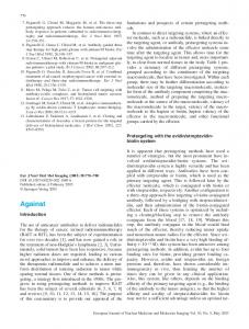
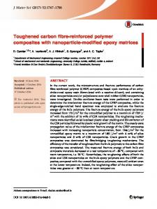
2. Stress analysis The same geometry of a composite cylinder model [9] used in a previous study [8] is adopted here. A semiinfinite long fibre with radius, a, is embedded in a coaxial cylindrical shell of matrix with an outer radius, b. As shown in Fig. I, r is the distance from the fibre axis, and z is the direction parallel to the fibre axis. The axial stress (0"0), which is compressive for pushdown (Fig. I a) and tensile for pullout (Fig. I b), is applied on the free end of the fibre at z = I. Sliding occurs at the unbonded fibre-matrix interface, beginning at the surface (z = I) and extending a depth I underneath the surface, such that the end of the sliding zone is located at z = O. Also, a surface step at the fibre-matrix interface is created due to the sliding. In the present study, both the fibre and the matrix are assumed to be isotropically elastic, and the interface transfers stresses from the fibre to the matrix by interfacial frictional shear stress, Ta. The complete solutions for fibre push-down have been derived previously [8], and the conditions used in deriving those solutions are summarized in the following. Certain simplification is required to obtain the analytical solution for fibre push-down in the composite. For a fibre with small diameter in the composite cylinder model (i.e., a 2jb 2 ~ I), the axial stress and displacement in the fibre are assumed to be independent of the radial coordinate, r. When an axial stress, 0"0' is applied at the fibre end, the stress transfers from the fibre to the matrix by the interfacial shear stress, T a , which is characterized by Coulomb friction [10]. 811
-1I
z=l
_.L t l•
i 1/ .:!.L"IJ
t I~
I
I
Figure 1 Schematic showing (a) the compressive stress (for fibre push-down) and, (b) the tensile stress (for fibre pull-out), 0'o, applied at the free end of an embedded fibre in the axial direction and the stress transfer from the fibre to the matrix by interfacial Coulomb friction, Ta' r .;; a: fibre, a .;; r .;; b matrix.
TQ~:t
~t ,
I
I
\
b~"i
z=o
(END OF SLIDING) I I I IZL.!.. I I r
I
I I
I (a)
(b)
The axial stress in the fibre (O"[) and the axial stress distribution in the matrix (O"rn) are in equilibrium with the applied axial stress (0"0), and the axial stress gradient in the fibre along the sliding length is in equilibrium with the interfacial shear stress [11,12]. At the fibre-matrix interface, continuity of the radial displacement is maintained when relative sliding in the axial direction between the fibre and the matrix occurs. Also, to maintain this continuity condition, a radial compressive stress is induced at the interface (due to Poisson's effect of the fibre) which superimposes on the clamping stress to contribute to the interfacial shear stress through Coulomb friction. At the end of the sliding zone (z = 0), the axial stress in the fibre is in equilibrium with the interfacial shear stress (i.e., assume an unbonded interface and equivalence of the static and the kinetic coefficients of friction [10)). Finally, the length of the sliding zone is determined from the continuity of the axial strain between the fibre and the matrix at z = O. It is noted that one difficulty exists in deriving results based on the above conditions for fibre pushdown [8]. At the surface (z = l), the axial stress in the fibre is equal to 0"0 and the total axial force in the matrix is zero (due to the equilibrium condition) but the free surface condition for the matrix (i.e., O"rn = 0 at z = I) is not specified in the analysis. However, the axial stress in the matrix (O"rn), which is a function of r, z and the properties of the composite, derived from the previous approach [8] is negligible at the surface (IO"rn/O"ol'" 1O- 2 atz = I). Hence, the deviation of the solutions from the exact solutions for fibre push-down is minimal [8]. The inability to strictly satisfy all of the essential boundary conditions is a result of the simplification used in the study [8] (e.g., the assumptions that the shear stress in the matrix to be inversely proportional to r and that the axial stress in the fibre to be independent of r). However, these problems do not alter the results in any substantial manner. The derivations of the solutions for fibre pullout are similar to those of fibre push-down. However, applications of the calculational procedures and boundary conditions for fibre push-down to fibre pullout require two corrections: a change in (1) the sign of the shear 812
stress regarding fibre sliding direction, and (2) the boundary condition used in deriving the length of the sliding zone. Without repeating the calculational procedures and boundary conditions, the present paper lists only the differences required for fibre pullout. For fibre pullout, the fibre slides (and hence the direction of frictional shear stress is) in the opposite direction compared with fibre push-down. In the case of fibre push-down, the relation between Coulomb frictional shear stress, La' and the resultant radial stress at the fibre-matrix interface is [8, 10] (1)
where J-l is the (kinetic) coefficient of friction, O"j is the interfacial radial compressive stress (negative) due to Poisson's expansion of the fibre resulting from the push-down stress, 0"0 (negative), and O"c is the radial clamping stress (compressive and negative) at the interface. This radial clamping stress can result from differential shrinkage during sintering [13] or from greater contraction of the matrix than the fibre during cooling from the fabrication temperature [14]. In the case of fibre pullout, Equation 1 becomes (2)
because the fibre slides in the opposite direction, and where O"j is the interfacial radial tensile stress (positive) due to Poisson's contraction of the fibre resulting from the pullout stress, 0"0 (positive). It is noted that the magnitude of O"c (negative) should be greater than O"j for fibre pullout to obtain Coulomb friction at the interface. Otherwise, the fibre will separate from the matrix and results in complete pullout. For fibre pullout, where Equation 2 must be used, the solution of the axial stresses in the fibre, 0"[, becomes [8] A3 [1 - exp (m2z)] A2
+ X[exp (mJz) - exp (m2z)] +
O"s
exp (m2z) (3)
where O"s is the axial stress in the fibre at the end of the
sliding zone (i.e., ar at z = 0), and is given by [8]
G-
The axial stresses at the inner (r = a) and the outer
(4)
m2) exp (mJ)
+
~) exp (m2/) --------------------------------------
(ml -
and the coefficients A 2 , A 3 , m l , m 2 and X are given by [8]
(r = b) surfaces of the matrix (aa and ab) are [8]
(Sb)
+
(Af - 4A2y/l]/2
(Sc)
[- Al - (Af - 4A2y/2]j2
(Sd)
[- Al
(Se) where E and v are Young's modulus and Poisson's ratio, respectively, the subscripts f and m denote the fibre and the matrix, respectively, and Al is given by [8] a2 _ a2 + a ( 1 - b2)(b2 a2 b2 +
211 vm(l
2
[ + vm) b In
Vm
+ Em Er (1 - vr) )
(b)~ - b 2 a 2
2
(7b)
and the axial stress distribution in the matrix is [8]
am =
aa
+
(ab - a.) In (r/a)/ln (b/a)
(7c)
Solutions of the interfacial properties Equations 3 to 7 are subject to the determination of the length of the sliding zone, If the same boundary condition used in determining I for fibre push-down is used to determine I for fibre pullout, substitution of I in Equation 7 yields high axial stresses in the matrix at the free surface (I am/ao 1'" 100 at z = I). Hence, modification of the boundary condition is required to obtain I for fibre pullout. To satisfy the condition of a free surface at z = I for the matrix, a a = 0 at z = I is required (see Equation 7). Adoption of this boundary d· . . Id con l110n Y1e s
I.
]
(Sf)
The interfacial shear stress, TO' and the axial displacements of the fibre, Wr and of the matrix at r = a, WO' are [8] T = - ~ ( - A3 m2 exp (m2z) + X[ml exp (mlz) a 2 A2 (6a) - m2 exp (m2z)] + a s m2 exp (m2 z))
[A3 m2 exp (m2/) - m l exp (mil) + (ml - m2) exp [(ml + m1)l] exp (mil) - exp (m2/) (ml - m1) exp [(ml + m2) I] Al exp (mil) - exp (m 2l) 211
+ -;; a c +
aD
(ml exp (mil) - m2 exp (mll) exp (mil) - exp (m2/)
exp (mlz) m2
1)
211
+ -;; Er (b 2 + a2
Vr
-- b2 2 + Em - a
)]
) Vm
+
1
-
(8)
Vr
The length of the sliding zone, I, can then be solved from Equations 4 and 8. With the solution of I, the solutions of the interfacial mechanical properties of the composite (Equations 3 to 7) are complete.
3. Results (6b) Wa
Specific results are computed using material properties for the technologically significant system of SiC-fibre-reinforced Al2 0 3 composites (Er = SOO GPa, Em = 400 GPa, Vr = 0.3 and Vm = 0.2S) and b/a = 10 to elucidate the essential trends.
3.1. Solution of the length of the sliding zone The solution of the length of the sliding zone is essen813
1.0 . . . . . - - - - , - - - - - , - - - , - - - - - - , - - - - ,
0.8
0.6
Equation 6
0.4 bO
-...
b'"
0.2
o
-0.2
-0.4
L -_ _
~
o
_ _ _- L_ _ _
5
10
~
__
15
~
___
~
20
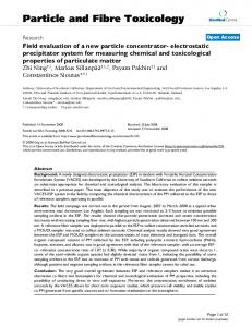
1/ a Figure 2 Example of determination of the length of the sliding zone for fibre pullout with coefficient of friction, J1 = 0.2, and ratio of the clamping stress to the applied axial stress, er,/ero = - 0.2. The intersection of the two curves yields the solution of the length of sliding zone and the axial stress in the fibre at the end of the sliding zone.
tial in deriving the complete solutions of the interfacial mechanical properties of the composite during fibre pullout. An analytical expression of I from Equations 4 and 8 is unattainable; however, / can be obtained by plotting (Js as a function of / from Equations 4 and 8. From the intersection of the two curves, the solutions of the length of the sliding zone, /, and the axial stress in the fibre at the end of the sliding zone, (Jso can be obtained. An example of the solution of the length of the sliding zone is given in Fig. 2 for (Jc/(Jo = - 0.2 and J1 = 0.2. With the solution of /, the solutions of fibre pullout can be obtained from Equations 3 to 7 and compared with the solutions of fibre push-down obtained in the previous study [8].
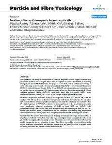
3.2. Comparisons of fibre pullout with fibre push-down The interfacial frictional shear stress, La' and the axial stress in the fibre, (Jr, are normalized with respect to the applied stress, (Jo, and are plotted as a function of the normalized embedded depth underneath the surface, (l - z)/a, for J1 = 0.2 in Fig. 3 at different ratios of (Jc/(Jo' The effects of the coefficient of friction on these stresses are shown in Fig. 4 for i (Jc/(Joi = 0.2. Figs 3a and 4a show that the interfacial shear stress is not constant. In the case of fibre pullout, Poisson's contraction of the fibre in the radial direction (due to the axial tension in the fibre) induces a radial tensile stress and reduces the resultant radial compressive stress (and hence the interfacial shear stress) at the interface. Since the axial tensile stress in the fibre
0.07 , - - - - , - - -....- - - , - - - - - - - ,
0.06
1.0 \ O'c 10'0=
0.05
\
0.2
\ \
0.04
\
EOS
\\ \~1 \
EOS
!
0.15 \EOS
~
-...
1\
\\ \\
\\
\\
0.6
~
"
';' 0.03
~
0.8
\\
\\ \\ I\
bO
-...
b 0.4
0.02
\ \0.15 0.2 \ \
(a)
0
\ \
0.2
0.01
0
10
20 [(l-z)/a)
30
40
0
\ \
(b)
0
\ \ \ \ 10
20
30
40
[(t-z) fa}
Figure 3 (a) Normalized interfacial shear stress and (b) normalized axial stress in the fibre as a function of normalized embedded depth underneath the surface, (l - z)/a, for J1 = 0.2 at different ratios of er,/er o' ( - pullout, - - - push-down, EOS end of sliding).
814
0.10
1.0
\ 0.08
'\ ......
0.06
--....
°
......
\.
",
c
0.04
"",\
0.8
\.
.......
0.2' ........
b I
~
\ \11-=0.3
--....
'\,,\
,,
0.6
bO
.......
b
.......
\
\ \0.2
\
0.4
\
0.3 \
\ 0.02
0
0.2
(a) 0
\
\
(b)
5
10
15
[{l-zJ/a]
0
0
5
\
\
\
,
\
\
\
\ 10
15
[(l-zl/a]
Figure 4 (a) Normalized interfacial shear stress and (b) normalized axial stress in the fibre as a function of normalized embedded depth underneath the surface, (l - z)/a, for 10",/0"01 = 0.2 and J1 = 0.2 and 0.3. ( - pullout, --- push-down).
decreases with the increase in the embedded depth underneath the surface (due to the stress transfer from the fibre to the matrix, see Figs 3b and 4b), the induced interfacial radial tensile stress decreases and hence the interfacial shear stress increases with the increase in the embedded depth underneath the surface (Figs 3a and 4a). Conversely, in the case of fibre push-down, Poisson's expansion of the fibre is induced, which in turn, results in the enhancement of the resultant radial compressive stress and the shear stress at the interface. The interfacial shear stress decreases with the increase in the embedded depth underneath the surface for fibre push-down. However, for both fibre pullout and pushdown, the interfacial shear stress increases and the axial stress in the fibre decreases as the radial clamping stress (Fig. 3) or the coefficient of friction (Fig. 4) increases. Also, since lTr/lT o is small at the end of the sliding zone, the magnitude of fa is slightly below II1 lTc I for fibre pullout and slightly above II1lTc I for fibre push-down at z = due to Poisson's effect of the fibre (Figs 3a and 4a). The axial stress in the fibre is equal to the applied stress at the surface (at z = I) and decreases to an absolute value equal to the interfacial shear stress at the end of the sliding zone (due to the assumption of equivalent static and kinetic coefficients of friction). Figs 3b and 4b show that the axial stress gradients along the embedded fibre length exhibit the opposite trend for fibre pullout and push-down. For fibre pullout, the increase in the interfacial shear stress along the embedded depth (Figs 3a and 4a) results in an increase in the stress transfer from the fibre to the matrix (through Coulomb friction) and hence an increase in the axial stress gradient in the fibre as the embedded depth underneath the surface increases. Conversely, for fibre push-down, the axial stress gradient in the fibre decreases with the increase in the embedded depth underneath the surface (Figs 3 and 4).
°
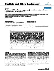
The normalized length of the sliding zone (i.e., I/a) is plotted as a function of the coefficient of friction, 11, at different ratios of lTc/lTo in Fig. 5a. For the same 11 and lTO' fibre pullout induces longer fibre sliding zone length, I, than does fibre push-down since the interfacial shear stress (and hence the resistance to sliding) is lower for fibre pullout. However, I decreases as the coefficient of friction or the clamping stress increases for both fibre pullout and push-down. The results in Fig. 5a are consistent with Figs 3 and 4, i.e., the increase in the interfacial shear stress, which resists the fibre sliding, results in a decrease in the length of the sliding zone. The surface step at the fibre-matrix interface is induced by the relative sliding between the fibre and the matrix during fibre pullout or push-down. The fibre and the matrix displacements in the loading direction, Wr and W a , are taken to be zero at the end of the sliding zone, z = 0, (see Equations 6b and 6c) and increase to the maximum values, wr and W., at the surface (z = I). It is noted that the surface step at z = I due to the loading equals the difference between wr and wa; however, since wr is always much larger than wa for small values of 11 ( < 0.5) [8], the surface step can be approximated by the value of wr. The normalized wr as a function of the coefficient of friction are plotted in Fig. 5b at different ratios of lTcilTo. It is shown that the surface step induced by fibre pullout is larger than fibre push-down. However, the surface step decreases when the radial clamping stress or the coefficient of friction increases for both fibre pullout and push-down (Fig. 5b).
3.3. Affects of Poisson's ratio of the fibre The differences between fibre pullout and fibre pushdown result from Poisson's effect of the fibre. It is instructive to consider the effects of Poisson's ratio of the fibre on the interfacial mechanical properties of composites. This is achieved by considering the material properties of SiC-fibre-reinforced A1 2 0 3 , 815
0.05
40
,-----~----~~----~---.------
,-----~------,,------._------~----~
0.04
30 ~
\
tJ
::::; 20
2
0.03
bO
\
tJ
\ \
'-
-0.2
\'\
,,~,
0.15 , ........ , 0.2 __ .::::- _ _
10
o
0.01
........
- .::= - == ::: -
(a)
L -_ _ _ _
o
~
_ _ _ _ _ __ L_ _ _ _ _ _
0.1
0.2
~
_ _ _ _ _ _L __ _ _ _
0.3
o
~
0.4
L(b) -_ _
o
0.5
~
__
~
0.1
_ _ _L-_ _
0.3
0.2
~
0.4
__
~
0.5
Figure 5 (a) Normalized length of sliding zone and (b) normalized maximum fibre displacement in the loading direction as a function of the coefficient of friction, /1, at different ratios of a,/ao' ( - pullout, - - - push-down).
crc!cro = ± 0.2 (+ 0.2 for push-down and - 0.2 for pullout), J1 = 0.1 and assuming arbitrarily Poisson's ratio of the fibre, Vf, ranging from 0 to 0.5. The normalized interfacial shear stress and the normalized axial stress in the fibre are plotted as a function of the normalized embedded depth underneath the surface for Vf = 0 and 0.3 in Figs 6a and 6b, respectively. For fibre pullout, when Vf increases, the Poisson's contraction of the fibre in the radial direction increases and the stress transfer from the fibre to the matrix becomes less effective. Hence, La decreases and crf increases with the increase in Vf. Conversely, fibre push-down shows the opposite trend. In the absence of Poisson's effect of the fibre (i.e., Vf = 0), fibre pullout and push-down show the identical normalized results. Also, the interfacial shear stress is constant (= ± J1crJ and the axial stress along the fibre length is 0.04
linear when Vf = O. The normalized length of the sliding zone and the normalized maximum fibre displacement as a function of Vf are shown in Figs 7a and b, respectively. For fibre pullout, I and wfincrease with the increase in Vf since the fibre sliding experiences less resistance as Vf increases Figs 6 and 7). The opposite trend is shown for fibre push-down. However, when Vf = 0, identical normalized solutions of I (and we) are obtained for fibre pullout and push-down (Fig. 7).
4. Conclusions The detailed analyses of fibre push-down for fibrereinforced composites with unbonded frictional interfaces have been shown in a previous paper [8]. The effects of the radial clamping (compressive) stress, the coefficient of friction, Young's moduli, and Poisson's ratios of the fibre and of the matrix on the interfacial 1.0
~----~------~------~----~
"
0.03
"
~---~---~---~--~
\ \
0.8 IIf
=0.3
" " "-
~ 0.02 __
\
\
0.6 ........
--....
...'"
\ \
b
I
\
\
bO
.......
\
0.4
\
0.3 \ \
0.01
\
0.2
o
(a)
L-____
o
~L_
10
____
~
_ _ _ _ _ __ L_ _ _ _ _ _
20
30
~
40
o
\
(b)
o
[(l-z)fa]
20
30
40
[( l-z) fa]
Figure 6 (a) Normalized interfacial shear stress and (b) normalized axial stress in the fibre as a function of normalized embedded depth underneath the surface, (I - z)/a, for I a)aol = 0.2, /1 = 0.1 and Poisson's ratio of the fibre, Vf = 0 and 0.3. When Vf = 0, fibre pullout
and push-down have identical normalized results. ( - pullout, - - - push-down).
816
-"
50
U.05
40
0.04
30
0
C>-
-- -- -----
20
0.03
S
bO t>
"-
0:.-
-- --
0.02
0.01
10
(0)
(b)
0
0 0
0.1
0.2
vf
0.3
0.4
0
0.5
0.1
0.2
vf
0.3
0.4
0.5
Figure 7 (a) Normalized length of the sliding zone, and (b) normalized maximum fibre displacement in the axial direction as a function of Poisson's ratio of the fibre, Vf, for 10',/0'" I = 0.2 and J1 = 0.1. (~O',/O'" = - 0.2 (pullout), - - - 0',/0'0 = 0.2 (push-down».
mechanical properties of the composites have been evaluated. Without repeating the calculational procedures and boundary conditions, the analysis for fibre push-down [8] was modified to describe the mechanical behaviour of fibre pullout in the present study. Unlike fibre push-down, a minimum radial clamping stress at the fibre-matrix interface is required for fibre pullout to maintain the contact between the fibre and the matrix. The results for fibre pullout are then used to compare with the previously obtained results for fibre push-down [8]. The specific results presented in the present study are for SiC-fibre-reinforced A1 2 0 3 • The effects of Poisson's ratios on the interfacial mechanical properties of the composites are revealed by assuming arbitrarily the values of Vr ranging from 0 to 0.5. However, the trends revealed are expected to be similar for other fibre-reinforced ceramic composites, albeit that specific numerical solutions must be material dependent. The present results show that fibre pullout and pushdown have the identical normalized results (normalized with respect to the applied stress) only when Poisson's ratio of the fibre is zero (Figs 6 and 7). Also, the interfacial shear stress is constant and the axial stress in the fibre along the sliding length is linear when Vr = 0 (Fig. 6). For a non-zero value of Vr, fibre pullout has lower interfacial shear stress (Figs 3b and 4b), longer sliding zone length, and greater fibre displacement in the loading direction (Fig. 5) than fibre push-down. Finally, it is noted that the present analysis is pertinent to the case for a composite subjected to a radial clamping stress at an unbonded interface. In the case of a bonded interface, debonding is required before sliding can occur, the axial stress in the fibre at the end of the sliding zone (rr.) becomes higher, and
the differences between fibre pullout and push-down are expected to be smaller than the predictions derived in the present study.
Acknowledgements The author thanks Drs P. F. Becher, M. K. Ferber and P. Angelini for reviewing the manuscript. Research sponsored by Division of Materials Sciences, Office of Basic Energy Sciences, US Department of Energy, under contract DE-AC05-840R21400 with Martin Marietta Energy Systems, Inc. References I.
D. B. MARSHALL,
B. N. COX
and
A. G. EVANS,
Acta Metall. 33 (1985) 2013. 2. 3. 4.
D. H. GRANDE, J. F. MANDELL and K. C. C. HONG, J. Mater. Sci. 23 (1988) 311. P. F. BECHER, C. H. HSUEH, P. ANGELINI and T. N. TIEGS, J. Amer. Ceram. Soc. 71 (1988) 1050. D. B. MARSHALL and W. C. OLIVER, ibid. 70 (1987)
542. 5.
T. FABER, S. H. ADVANI, J. K. LEE and T. J\ N N, ibid. 69 (1986) C208. 6. K. SHETTY, ibid. 71 (1988) C107. 7. H. HSUEH, ibid. 71 (1988) 490. 8. H. HSUEH, J. Mater. Sci., submitted. 9. Z. HASHIN and B. W. ROSEN, J. Appl. Mech. 31 (1964) 223. 10. M. ALONSO and E. J. FINN, "Physics" (AddisonWesley, Reading, Massachusetts, 1970). II. P. LAWRENCE, J. Mater. Sci. 7 (1972) I. 12. M. R. PIGGOTT, "Load Bearing Fiber Composites" (A. Wheaton & Co Ltd, Exner, UK, 1980). 13. C. H. HSUEH, A. G. EVANS, R. M. CANNON and R. J. BROOK, Acta Metall. 34 (1986) 927. 14. C. H. HSUEH, P. F. BECHER and P. ANGELINI, J. Amer. Ceram. Soc. 71 (1988) 929. K. J. D. C. C.
Received 8 November 1988 and accepted 10 April 1989
817