Article
Fluid Flow Shear Stress Stimulation on a Multiplex Microfluidic Device for Rat Bone Marrow Stromal Cell Differentiation Enhancement † Chia-Wen Tsao 1, *, Yu-Che Cheng 2,3,4 and Jhih-Hao Cheng 1 Received: 28 October 2015; Accepted: 7 December 2015; Published: 11 December 2015 Academic Editors: Shih-Kang Fan, Da-Jeng Yao and Yi-Chung Tung 1 2 3 4
* †
Department of Mechanical Engineering, National Central University, 32001 Taoyuan, Taiwan;
[email protected] Proteomics Laboratory, Cathay General Hospital, 22174 New Taipei City, Taiwan;
[email protected] Institute of Biomedical Engineering, National Central University, 32001 Taoyuan, Taiwan School of Medicine, Fu Jen Catholic University, 24205 New Taipei City, Taiwan Correspondence:
[email protected]; Tel.: +886-3-426-7343; Fax: +886-3-425-4501 This paper is an extended version of our paper presented in the 5th International Conference on Optofluidics 2015, Taipei, Taiwan, 26–29 July 2015.
Abstract: Microfluidic devices provide low sample consumption, high throughput, high integration, and good environment controllability advantages. An alternative to conventional bioreactors, microfluidic devices are a simple and effective platform for stem cell investigations. In this study, we describe the design of a microfluidic device as a chemical and mechanical shear stress bioreactor to stimulate rat bone marrow stromal cells (rBMSCs) into neuronal cells. 1-methyl-3-isobutylxanthine (IBMX) was used as a chemical reagent to induce rBMSCs differentiation into neurons. Furthermore, the shear stress applied to rBMSCs was generated by laminar microflow in the microchannel. Four parallel microfluidic chambers were designed to provide a multiplex culture platform, and both the microfluidic chamber-to-chamber, as well as microfluidic device-to-device, culture stability were evaluated. Our research shows that rBMSCs were uniformly cultured in the microfluidic device and differentiated into neuronal cells with IBMX induction. A three-fold increase in the neuronal cell differentiation ratio was noted when rBMSCs were subjected to both IBMX and fluid flow shear stress stimulation. Here, we propose a microfluidic device which is capable of providing chemical and physical stimulation, and could accelerate neuronal cell differentiation from bone marrow stromal cells. Keywords: microfluidics; rat bone marrow stromal cell; stem cell stimulation; fluid flow shear stress; neuronal cell differentiation
1. Introduction Microfluidic devices, an integrated system incorporate various function such as pumping, mixing, sample separation, sample concentration, and culturing in a single chip for chemical or biological analysis. Micro total analysis system (µTAS) or lab-on-a-chip (LOC) are sometimes also referred to as microfluidic technologies. In recent decades, microfluidics has become a widely used platform for cell investigations. Compared to conventional cell culture techniques in a Petri dish, microfluidics offers low sample/reagent consumption, which offers high integration, high automation, and a real-time monitoring cell culture approach [1]. Due to these advantages, various unique microfluidic cell investigations have been demonstrated. For example, Emneus et al. developed a long-term, real-time microfluidic device to monitor human cells (HFF11) [2]. Ramsey’s group integrated cell separation and mass spectrometry in a chip for cell analysis [3]. Single-cell Micromachines 2015, 6, 1996–2009; doi:10.3390/mi6121470
www.mdpi.com/journal/micromachines
Micromachines 2015, 6, 1996–2009
sorting and analysis can be achieved based on droplet microfluidics [4]. Polydimethylsiloxane (PDMS) soft elastomer is the most commonly used material in cell culture microfluidic devices because of its good biocompatibility, gas permeability, and optical transmissivity [5,6]. Since PDMS-based microfluidic devices are mainly fabricated by a soft lithography process, the cell culture microchannel geometry can be precisely controlled and tailored to various shapes for cell culture investigations [7]. With further integration of PDMS microfluidic valves, high throughput screening can be achieved in such microfluidic devices [8]. Besides, conventional Petri dish is a two-dimensional environment. Microfluidics provides a three-dimensional microenvironment that provide more in vivo conditions for cell investigations [9]. Recently, microfluidics devices have moved to organs-on-chips [10,11] applications, which use microfluidic techniques to mimic organs in biochemical microenvironment for in vitro disease models. Of the research conducted in cell investigations, stem cells have the ability of self-renewal and can differentiate into specific cell types through environmental stimuli. Due to their potential to regenerate and repair damaged tissue, stem cells have been applied to various promising applications, such as tissue engineering or cell-based therapies. Chemical and physical factors, which influence stem cell differentiation have been extensively studied and are known to have significant effects on cell differentiation [12]. Recently, in addition to chemical signals, mechanical forces are also found to affect stem cell differentiation. Mechanical forces, such as hydrostatic pressure [13–15], shear stress [16,17], and tensile strain [18,19] have critical roles in deciding stem cell fate. While conventional methods studying mechanical force effects normally require complex, custom-made bioreactor designs, microfluidic devices offer a simple, low-cost alternative choice for stem cell investigations [20,21]. Microfluidic devices provide good environmental regulatory ability to mimic in vivo microenvironment, which is ideal for stem cell investigations. Since microfluidic devices are a dynamic profusion-based environment, liquid phase chemical reagents can simply be replaced or injected into the microchannel for chemical stimuli research. Research in cell chemotaxis can be easily performed while further integrating a microfluidic gradient generator [22]. In mechanical stress stimulation experiments, a conventional bioreactor uses a compressive loading cylinder [23], rotating cone [24,25], or parallel plate chamber [26] to generate hydrostatic pressure or shear stress on cells. With a microfluidic device, on the other hand, physical shear stress can be simply created by fluid flow induction from laminar microflow behavior [27], and hydrostatic pressure can be created by a vortex in the PDMS chamber [28]. These examples show that the microfluidic device is a simple and effective approach to study the mechanical stress effects on stem cells. Therefore, in this study, we used a microfluidic device as a chemical and mechanical shear stress bioreactor to stimulate rat bone marrow stromal cells (rBMSCs). The effects of chemical and mechanical shear stress on the rBMSCs were reported in this investigation. Four parallel microfluidic rBMSCs cultures and differentiation chamber designs were used in this study to highlight potential of high-throughput screening. 2. Experimental Section 2.1. Materials and Reagents Materials and reagents for microfluidic device fabrication are listed as below. A 10-cm diameter P-type (100) single-side polished silicon wafer with a resistivity of 1–100 Ω¨ cm was purchased from Summit-Tech Resource Corp. (Hsinchu, Taiwan). SU-8 3050 kit including SU-8 photoresist and SU-8 developer was purchased from MicroChem Corp. (Newton, MA, USA). PDMS elastomer kit including PDMS base and curing agent (Sylgard 184 silicone elastomer kit) was purchased from Dow Corning Corp. (Midland, MI, USA). Stainless steel surgical needles (SC20/15) were purchased from Instech Laboratories Inc. (Plymouth Meeting, PA, USA). Medical grade plastic tubing (Tygon S-50-HL) were purchased from Saint-Gobain Performance Plastics (Akron, OH, USA). 75 mm ˆ 25 mm ˆ 1 mm microscope glass slides were purchased from Doger Instruments Co. Ltd
1997
Micromachines 2015, 6, 1996–2009
(Taipei, Taiwan). Acetone (ACE) and isopropyl alcohol (IPA) were purchased from J.T. Baker (Phillipsburg, NJ, USA). Materials and reagents for rBMSCs culturing and differentiation experiments are listed as below. Culture Petri dishes (Nunc) were purchased from Thermo Fisher Scientific (Waltham, MA, USA). Primary antibodies against the human neuron-specific enolase (NSE, 1:25) and 1-methyl-3-isobutylxanthine (IBMX) were purchased from Sigma-Aldrich (St. Louis, MO, USA). Avidin-biotin conjugate of horseradish peroxidase and Vector VIP substrate kit were purchased form Vector Laboratories (Burlingame, CA, USA). Dulbecco’s modified Eagle medium (DMEM) and Penicillin/Streptomycin (P/S) were purchased from Gibco/Life Technologies (Carlsbad, CA, USA). Fetal Bovine Serum (FBS) were purchased from HyClone/GE Healthcare (Novato, CA, USA). 2.2. Rat Bone Marrow Stromal Cell Preparation rBMSCs were harvested from eight-week-old Sprague–Dawley rats. Cell cultures were maintained at 37 ˝ C with 5% CO2 in a 10 cm diameter culture dish with culture medium which consisted of DMEM with 10% FBS, 100 U/mL penicillin, and 100 g/mL streptomycin. rBMSCs used in this study maintained in 20–25 passages for strong proliferation potential. 2.3. 41 ,6-Diamidino-2-Phenylindole (DAPI) and Immunocytochemistry (ICC) Staining Procedures 41 ,6-Diamidino-2-Phenylindole (DAPI) staining was performed on the rBMSCs to ensure accurate cell number calculations for the rBMSCs cell growth experiments. The DAPI staining process is performed directly on the microfluidic bioreactor and the detailed staining procedure is illustrated below. A PBS rinse was performed between each chemical injection step. The following on-chip staining was operated at room temperature and injected with 1.5 µL/min unless described elsewhere. First, we injected 4% paraformaldehyde for 10 min to fix the cells followed by the PBS rinse. Then, we injected 0.1% Triton-X 100 for 4 min to permit cell permeabilization. Finally, diluted DAPI solution (DAPI: PBS, 1:800, v/v) was injected into the microchannel to stain the rBMSCs cell nucleus. Similar to DAPI staining, the immunocytochemistry (ICC) staining process was performed in this study to confirm the neuronal cell type and ensure accurate neuronal cell calculation. The ICC staining process was also performed directly on the microfluidic bioreactor and the staining procedure was illustrated as follows. The rBMSCs were first treated with paraformaldehyde and Triton-X 100 to fix and permeabilize the cells, which is identical to the DAPI staining process as described above. Then, 3% H2 O2 solution was injected into the microchannel and allowed to rest for 30 min before 1.5% normal horse serum was injected into the microchannel. This was allowed to rest for 30 min and was followed by a PBS rinse. Next, rBMSCs were treated with primary antibody against the human antigen neuron-specific enolase and incubated at 37 ˝ C for 1 h. After primary antibody treatment, the cells were then stained with biotinylated anti-rabbit antibody followed by an avidin-biotin conjugated horseradish peroxidase for 30 min. Finally, Vector VIP substrate kit was introduced to the microfluidic chamber as a visualization reagent to reveal the resulting peroxidase activity. 2.4. Microfluidic Device Fabrication Fabrication of the microfluidic device is based on a standard PDMS soft lithography process which requires micromold fabrication and PDMS replication process as shown in Figure 1a–c and Figure 1d–f, respectively. In micromold fabrication, the bare silicon wafer was first cleaned with acetone (ACE), isopropyl alcohol (IPA), and deionized (D.I.) water, followed by baking at 130 ˝ C for 15 min on a hot plate (Super-Nuova, Barnstead Thermolyne, Waltham, MA, USA) to remove the moisture on the silicon surface for enhanced SU-8 attachment. Then, spin coat (SPC-703, Yi YANG Co., Taoyuan, Taiwan) SU-8 photoresist was added to the silicon substrate (Figure 1a). The spin coating speed was set at 500 rpm for 30 s and 1000 rpm for 40 s. After spin coating, the SU-8 layer was subject to UV exposure for 90 s (AGL100 UV Light source, M & R Nano Technology 1998
Micromachines 2015, 6, 1996–2009
Co., Taoyuan, Taiwan) via a patterned transparent film mask (Ching Acme Enterprises Corp., Taipei, Taiwan) to generate microchannel patterns on the SU-8 layer (Figure 1b). Immersed, UV-exposed SU-8 substrate in SU-8 developer for 3–5 min to create a SU-8 micromold for the subsequent PDMS replication (Figure 1c). After SU-8 micromold fabrication, PDMS casting was performed to Micromachinesprocess 2015, 6, page–page create the microchannel. The PDMS replication process started with pouring a 10:1 volume ratio of Sylgard base and curing agent mixture overmicromold the SU-8 micromold before degassing in a vacuum base and184 curing agent mixture over the SU-8 before degassing in a vacuum oven to oven to remove the air bubbles inside the layer. PDMSThen, layer.the Then, the layer PDMSwas layer wasatcured 70 4˝ Ch remove the air bubbles inside the PDMS PDMS cured 70 °Catfor for 4 h (Figure 1d), removed from themicromold SU-8 micromold O2 plasma a glass (Figure 1d), removed from the SU-8 and Oand 2 plasma bond bond PDMSPDMS with awith glass slide slide (Duffy al. 1998) O2 plasma cleaner (PDC-32G, Harrick Plasma,Ithaca, Ithaca,NY, NY,USA) USA) for for 150 ss (Duffy et al.et1998) in Oin 2 plasma cleaner (PDC-32G, Harrick Plasma, (Figure (Figure 1e). 1e). Punch fluid inlet and outlet holes was conducted using a biopsy punch punch (Harris (Harris Uni-Core, Uni-Core, Sigma-Aldrich, Louis, MO, MO, USA) USA) and and inserted inserted stainless steel surgical needles as microfluidic Sigma-Aldrich, St. St. Louis, microfluidic bioreactors outlet connectors connectors (Figure (Figure 1f). 1f).Medical Medicalgrade gradeplastic plastic tubing was used bioreactors for injection and outlet tubing was used to to connect the needle inject connector to the syringe pump or waste beaker. connect the needle inject connector to the syringe pump or waste beaker. All All microfluidic microfluidic channels, channels, plastic plastic tubes, tubes, surgical needles, needles, and injection syringes were were fully fully sterilized sterilized to to prevent prevent cell cell contamination contamination during during experiments. experiments. The plastic tube, surgical surgical needles, needles, and and injection injection syringe syringe were were cleaned cleaned by by immersion immersion in in 75% 75% alcohol alcohol solution solution followed followed by by UV UV sterilization sterilization at at 30 30 min. min. After UV sterilization, the microfluidic bioreactor was connected to to the the syringe syringe pump, pump, and and Dulbecco’s Dulbecco’s Phosphate Phosphate Buffered Buffered Saline Saline (DPBS) (DPBS) was was flushed flushed into into the the microchannel microchannel for for 90 90 min min to to clean clean the the microchannel microchannel walls. walls.
Figure 1. 1. Schematic illustration of of SU-8 SU-8 micromold micromold fabrication fabrication procedure: procedure: (a) (a) silicon silicon wafer wafer cleaning cleaning Figure Schematic illustration and spin (b) (b) UV exposure, (c) SU-8 and PDMS process, (d)process; casting and spincoat coatSU-8, SU-8; UV exposure; (c)development SU-8 development andreplication PDMS replication 2 plasma bonding PDMS layer with glass substrate, and the PDMS on SU-8 micromold, (e) O (d) casting the PDMS on SU-8 micromold; (e) O2 plasma bonding PDMS layer with glass substrate; (f) photography of PDMS microchannel withwith blueblue color dye dye injection. and (f) photography of PDMS microchannel color injection.
3. Results and Discussion 3. Results and Discussion 3.1. rBMSCs rBMSCs Culture Culture and and Stability Stability in in the the Four Four Parallel Parallel Microfluidic Microfluidic Chambers Chambers 3.1. The rBMSCs rBMSCs were were cultured cultured and and differentiated differentiated into into neuronal neuronal cells cells in in aa microfluidic microfluidicdevice. device. The The The microfluidic device design layout and experiment setup are shown in Figure 2. The microchannel microfluidic device design layout and experiment setup are shown in Figure 2. The microchannel consists of of aa 11 mm mm diameter diameter inlet inlet and and outlet outlet port port for forsurgical surgicalstainless stainlessneedle needleinsertion. insertion. The The consists microfluidic device device injection injection inlet inlet was was connected connected to to the the syringe syringe pump pump and and the the outlet outlet was was connected connected microfluidic to the waste beaker through a plastic surgical tube, respectively. The microchannel is 200 μm in width width to the waste beaker through a plastic surgical tube, respectively. The microchannel is 200 µm in ˝ ˝) and 100 100 µm μm in in height. height. Two Two Y-shaped Y-shapedmicrochannel microchannelsplitters splitters(first (firstsplitter: splitter:44 44°, secondsplitter: splitter: 25 25°) and , second split the the flow flow equally equally into into the the four four microfluidic microfluidic chambers chambers (dimensions: (dimensions: 44 mm mm length, length, 11 mm mm width, width, split and 0.1 mm height), where rBMSCs culture and differentiation took place. The microfluidic device system was placed inside the CO2 incubator (SCA-165DRS, ASTEC, Fukuoka, Japan) and maintained 1999 at 37°C and 5% CO2 concentration. The rBMSCs culture started with a dynamic injection in the inlet port of ~10 μL of 106 cells/mL rBMSCs suspension at 2 μL/min to seed the rBMSCs in the four microfluidic chambers. The seeding
Micromachines 2015, 6, 1996–2009
and 0.1 mm height), where rBMSCs culture and differentiation took place. The microfluidic device system was placed inside the CO2 incubator (SCA-165DRS, ASTEC, Fukuoka, Japan) and maintained at 37˝ C and 5% CO2 concentration. The rBMSCs culture started with a dynamic injection in the inlet port of ~10 µL of 106 cells/mL rBMSCs suspension at 2 µL/min to seed the rBMSCs in the four microfluidic chambers. The seeding procedure was operated under inverted microscope to check the cells are fully injected into each Micromachines 6, page–page chambers. After2015, rBMSCs seeding, the cells were left in the CO2 incubator without motion for 24 h Micromachines 2015, 6, page–page under stable conditions, allowing the rBMSCs to fully adhere to the microfluidic chamber. As under stable conditions, allowing the rBMSCs to fully adhere to the microfluidic chamber. As shown shown in Figure 3a, around 1 µm diameter rBMSCs suspension can clearly be found and were in Figure 3a,conditions, around 1 μm diameter suspension cantoclearly be found and were uniformly under stable allowing the rBMSCs to fully adhere the microfluidic chamber. As shown uniformly distributed inside the microfluidic chamber right after the rBMSCs suspension injection distributed the1 microfluidic after the suspension step. As in Figure 3a,inside around μm diameterchamber rBMSCs right suspension canrBMSCs clearly be found andinjection were uniformly step. distributed As shown in Figure 3b, spindle-like rBMSCs morphology was uniformly distributed inside shown in Figure 3b, microfluidic spindle-like rBMSCs morphology uniformly distributed inside inside the chamber right after the was rBMSCs suspension injection step. the As the microfluidic chamber, which indicates that the rBMSCs were tightly adherent to the microfluidic microfluidic chamber, indicates that the rBMSCs were adherent to the microfluidic shown in Figure 3b, which spindle-like rBMSCs morphology wastightly uniformly distributed inside the device substrate. device substrate. microfluidic chamber, which indicates that the rBMSCs were tightly adherent to the microfluidic device substrate.
Figure 2. Schematic illustration of rBMSCs fluid flow stimulation microchannel design and
Figure 2. Schematic illustration of rBMSCs fluid flow stimulation microchannel design and experimental setup. illustration of rBMSCs fluid flow stimulation microchannel design and Figure 2. Schematic experimental setup. experimental setup.
Figure 3. Microscopy images of rBMSCs seeding after (a) cell suspension injection and (b) 24 h static seeding. Figure 3. Microscopy images of rBMSCs seeding after (a) cell suspension injection and (b) 24 h Figure 3. Microscopy images of rBMSCs seeding after (a) cell suspension injection and (b) 24 h static seeding.
staticIn seeding. the high-throughput microfluidic device, cell culture stability is important to ensure good cell culture uniformity, as well microfluidic as controlleddevice, chemical physical stimulation conditions all In the high-throughput cell and culture stability is important to ensureamong good cell microfluidic chambers. In theory, the hydraulic resistance of fourstimulation parallel microfluidic is culture uniformity, as well as controlled chemical and physical conditions channels among all identical andchambers. delivers equal amounts of rBMSCs and fluidofflow stress to each microfluidic microfluidic In theory, the hydraulic resistance four shear parallel microfluidic channels is 2000 chamber. and However, of the microfabrication the culture identical deliversbecause equal amounts of rBMSCs andvariations, fluid flow fluid shearflow stressastowell eachasmicrofluidic conditionsHowever, for the four parallel chamber may vary. theasmicrofluidic chamber. because of themicrofluidic microfabrication variations, fluid Therefore, flow as well the culture conditions for the four parallel microfluidic chamber may vary. Therefore, the microfluidic
Micromachines 2015, 6, 1996–2009
In the high-throughput microfluidic device, cell culture stability is important to ensure good cell culture uniformity, as well as controlled chemical and physical stimulation conditions among all microfluidic chambers. In theory, the hydraulic resistance of four parallel microfluidic channels is identical and delivers equal amounts of rBMSCs and fluid flow shear stress to each microfluidic chamber. However, because of the microfabrication variations, fluid flow as well as the culture Micromachines page–page conditions for 2015, the 6,four parallel microfluidic chamber may vary. Therefore, the microfluidic chamber-to-chamber and device-to-device culture stability were evaluated. Figure 4 shows the bright chamber-to-chamber and device-to-device culture stability were evaluated. Figure 4 shows the bright field microscopic and DAPI staining images of rBMSCs inside the four microfluidic chambers. The field microscopic and DAPI staining images of rBMSCs inside the four microfluidic chambers. The rBMSCs were uniformly distributed and cultured inside each individual microfluidic chamber, but rBMSCs were uniformly distributed and cultured inside each individual microfluidic chamber, but the cell number among individual microfluidic wasfound foundtotobebe slightly different. the cell number among individual microfluidicchambers chambers was slightly different.
Figure 4. Microscopy (left) and DAPI-stained (right) images of rBMSCs culturing conditions in the
Figure 4. Microscopy (left) and DAPI-stained (right) images of rBMSCs culturing conditions in the microfluidic chambers 1–4. microfluidic chambers 1–4.
To quantify the cell number inside the microfluidic chamber, the DAPI staining images taken from the fluorescence (ECLIPSE Ti-U, Nikon, Tokyo, Japan) were further analyzed by thetaken To quantify the cell microscope number inside the microfluidic chamber, the DAPI staining images image analysis software ImageJ to calculate the cell number inside the microfluidic chambers. from the fluorescence microscope (ECLIPSE Ti-U, Nikon, Tokyo, Japan) were further analyzed Figure 5 shows the rBMSCs number from microfluidic chambers 1–4. Four individual microfluidic by the image analysis software ImageJ to calculate the cell number inside the microfluidic devices were fabricated to evaluate the microfluidic chamber-to-chamber as well as microfluidic chambers. Figure 5 shows the rBMSCs number from microfluidic chambers 1–4. Four individual device-to-device variations. In microfluidic Device 1, the DAPI stained rBMSCs inside the microfluidic devices were fabricated to evaluate the microfluidic chamber-to-chamber as well as microfluidic chamber numbered 138 (Chamber 1), 178 (Chamber 2), 167 (Chamber 3), and microfluidic device-to-device variations. microfluidic Device the 1, the DAPI stained rBMSCs inside 237 (Chamber 4), with an average value ofIn181 ± 43 cells. Similarly, rBMSCs inside the microfluidic the microfluidic chamber numbered 138 (Chamber 1), 178 (Chamber 2), 167 (Chamber chambers numbered 156/254/177 (Chamber 1), 140/224/237 (Chamber 2), 175/234/171 (Chamber 3), 3), and 237 (Chamber 4), with an average value of value 181 ˘ 43 ±cells. inside the and 227/207/202 (Chamber 4), with an average of 175 38/230 ±Similarly, 20/197 ± 30the cellsrBMSCs for microfluidic Device 2/Device 3/Device 4. From the DAPI stained cell number data, the microfluidic chamber-to-chamber relative standard deviation percentage (RSD%) was measured 2001 as 23.5%, 21.7%, 8.5%, and 15.2% for devices 1–4, respectively. The microfluidic chip-to-chip RSD% value was measured at 28.2%, 22.8%, 17.0%, and 6
Micromachines 2015, 6, 1996–2009
microfluidic chambers numbered 156/254/177 (Chamber 1), 140/224/237 (Chamber 2), 175/234/171 (Chamber 3), and 227/207/202 (Chamber 4), with an average value of 175 ˘ 38/230 ˘ 20/197 ˘ 30 cells for microfluidic Device 2/Device 3/Device 4. From the DAPI stained cell number data, the microfluidic chamber-to-chamber relative standard deviation percentage (RSD%) was measured as 23.5%, 21.7%, 8.5%, and 15.2% for Micromachines 2015, 6, page–page Devices 1–4, respectively. The microfluidic chip-to-chip RSD% value was measured at 28.2%, 22.8%, 17.0%, and 7.9% for Chambers 1–4, respectively. Compared with multiplex fluid flow delivery 7.9% for Chambers 1–4, respectively. Compared with multiplex fluid flow delivery microfluidic microfluidic device with 34.7% volume variation between microfluidic channels [29]. The fluid-flow device with 34.7% volume variation between microfluidic channels [29]. The fluid-flow driven driven microfluidic device shows good stability an overall average RSD% of 17.3% between microfluidic device shows good stability withwith an overall average RSD% of 17.3% between microfluidic chambers and an overall average RSD% of 18.9% between microfluidic device events. microfluidic chambers and an overall average RSD% of 18.9% between microfluidic device events.
Figure 5. rBMSCs number uniformity in four microfluidic chamber.
Figure 5. rBMSCs number uniformity in four microfluidic chamber.
In the microfluidic system, the shear stress is generated by the fluid flow injection and stimulates rBMCs. This concept is based the stress laminar Navier–Stokes theory, the flow the In the microfluidic system, theon shear is flow generated by the fluid flowsince injection and in stimulates microfluidic chamber is laminar, Newtonian flow, and incompressible. The shear stress in the rBMCs. This concept is based on the laminar flow Navier–Stokes theory, since the flow in the = incompressible. . Where μ is the fluid dynamic microfluidic chamber canNewtonian be estimated flow, as microfluidic chamber is surface laminar, and The shear viscosity, stress in the Q is the fluid injection flow rate, h is the chamber height, 6µQ and w is chamber width. Thus, the microfluidic chamber surface can be estimated as τwall “ . Where µ is the fluid dynamic mechanical shear stress generated on the cell chamber is proportionally relative to the flow rate. For wh2 viscosity, Q is the fluid injection flow rate, h is the chamber height, and wflow is chamber a Y-shaped splitter with equal microchannel width delivering an equal rate into width. each cellThus, the mechanical shear stress cellmicrofluidic chamber ischamber proportionally relative flow rate. chamber, the shear stressgenerated generatingoninthe each is the same. Withtoa the different For aY-shaped Y-shapedmicrochannel splitter with equal width delivering equalwill flow into each width, themicrochannel shear stress generated in each cell an chamber berate different. This cell provides in studying differentinshear effects on achamber single chip, cell culture chamber, the benefits shear stress generating eachstress microfluidic is and the its same. Withstability a different within different microchannels require further characterization. Figure 6 shows thebemicrofluidic Y-shaped microchannel width, thewill shear stress generated in each cell chamber will different. This device with 300, 400, 500, and 600 μm microchannel width connecting to cell Chambers 2, 3, and 4, provides benefits in studying different shear stress effects on a single chip, and its cell1,culture stability respectively. rBMSCs cell culture results show that the cell number inside Chambers 1, 2, 3, and 4 within different microchannels will require further characterization. Figure 6 shows the microfluidic were measured as 276, 337, 428, and 438, respectively. Since the cell number inside the chamber is device with 300, 400, 500, and 600 µm microchannel width connecting to cell Chambers 1, 2, 3, and 4, related to the flow rate injected into the microchamber and the fluid flow split into each microchannel respectively. rBMSCs cell culture results show that the cellnetwork. numberBased insideonChambers 1, 2,resistance, 3, and 4 were is based on the hydraulic resistance of each microchannel the hydraulic measured as 276, 337, 428, and 438,chambers respectively. Sincehigher the cellhydraulic number inside the chamber related to smaller microchannel width exhibit resistance than the islarger the flow rate injected intochambers. the microchamber the fluid flow split into each microchannel based microchannel width Therefore, and an increased cell number tendency shows with is the on themicrochannel hydraulic resistance of each microchannel network. Based on the hydraulic resistance, smaller width. The cell number in Chamber 4 is 1.6 times higher than Chamber 1. However, small cell width numberchambers differenceexhibit such ashigher cell number in Chambers 3 and 4 may still bemicrochannel observed due to microchannel hydraulic resistance than the larger width the chamber-to-chamber variation. the previous rBMSCs number uniformity test with the same chambers. Therefore, an increased cellIn number tendency shows with the microchannel width. The cell microchannel width 5), higher the average number1.variation between number in Chamber 4 is (Figure 1.6 times thancell Chamber However, smalleach cell chamber-to-chamber number difference such event is 17.2%. as cell number in Chambers 3 and 4 may still be observed due to the chamber-to-chamber variation. In the previous rBMSCs number uniformity test with the same microchannel width (Figure 5), the average cell number variation between each chamber-to-chamber event is 17.2%.
2002 7
Micromachines 2015, 6, 1996–2009
Micromachines 2015, 6, page–page
Figure Figure 6. 6. rBMSCs rBMSCsfluid fluidflow flow shear shear stress stress microfluidic microfluidic chip chip with with different different microchannel widths.
3.2. 3.2. Induction Induction of of rBMSCs rBMSCs Differentiation Differentiation into into Neuronal Cells by IBMX Stimulation To ensuregood goodcell cell culture differential stability, we aused a microfluidic device with To ensure culture andand differential stability, we used microfluidic device with identical identical microchannel for the IBMXand chemical and physical stress experiments stimulation microchannel width for width the IBMX chemical physical shear stress shear stimulation experiments rBMSCs. Thewere rBMSCs were cultured cell number approached 400 inside cells inside rBMSCs. The rBMSCs cultured until theuntil cell the number approached 400 cells each each microfluidic chamber seeding. a previousinvestigation investigation[30], [30],we we showed showed that chemical microfluidic chamber afterafter seeding. In In a previous chemical IBMX IBMX can can efficiently efficiently stimulate stimulate human human placenta-derived placenta-derived stem stem cells cells to to differentiate differentiate into into neuronal neuronal cells. cells. Neuronal cells can be clearly identified by their cell morphology under optical microscopy. Thus, in Neuronal cells can be clearly identified by their cell morphology under optical microscopy. Thus, this research, wewe applied IBMX to todifferentiate in this research, applied IBMX differentiaterBMSCs rBMSCsinto intoneuronal neuronalcells cells on on the the microfluidic microfluidic bioreactor to study the chemical as well as mechanical shear stress effects on rBMSCs. Figure 7 shows7 bioreactor to study the chemical as well as mechanical shear stress effects on rBMSCs. Figure the rBMSCs stimulation results under IBMX concentrations from 0.2–0.6 mM shows the rBMSCs stimulation results under IBMX concentrations from 0.2–0.6 mMand andneuronal neuronal cell dendrites, dendrites, as as well well as as condensed condensed and and round round cell cell bodies bodies could could be be observed observed under under optical optical microscopy, microscopy, which indicated successful neuronal cell differentiation under IBMX influence. Because the which indicated successful neuronal cell differentiation under IBMX influence. Because the IBMX IBMX is is toxic toxic to to rBMSCs rBMSCs at at high high concentration. concentration. The The rBMSCs rBMSCs differentiation differentiation ratio ratio is is tested tested under under 0.2–0.6 0.2–0.6 mM mM gradient gradient concentration, concentration, and and the the rBMSCs rBMSCs differentiation differentiation ratio ratio by by IBMX IBMX is is summarized summarized in in Figure Figure 7f. 7f. From this chart, it can be shown that the neuronal cell differentiation ratio increased with increasing From this chart, it can be shown that the neuronal cell differentiation ratio increased with increasing IBMX 0.5–0.6 mM mM IBMX. IBMX. IBMX concentrations. concentrations. The The differentiation differentiation ratio ratio reached reached aa plateau plateau at at around around 0.5–0.6
2003 8
Micromachines 2015, 6, 1996–2009
Micromachines 2015, 6, page–page
Figure Figure 7. 7. rBMSCs rBMSCsunder under(a) (a)0.2 0.2 mM, mM, (b) (b) 0.3 0.3 mM, mM, (c) (c) 0.4 0.4 mM, mM, (d) (d) 0.5 0.5 mM, mM, and and (e) (e) 0.6 0.6 mM mM IBMX IBMX stimulation. (f) Neuronal cell differentiation ratio under various IBMX concentration. Y-axis stimulation. (f) Neuronal cell differentiation ratio under various IBMX concentration. Y-axis indicates indicates neuronal the IBMX IBMX concentration concentration (mM). (mM). neuronal cell cell differentiation differentiation ratio ratio and and X-axis X-axis indicates indicates the
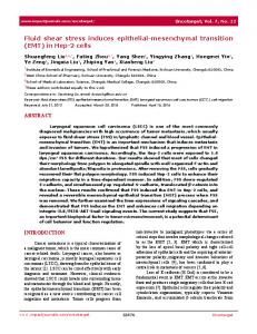
3.3. 3.3. Effects Effects of of Fluid Fluid Flow Flow Shear Shear Stress Stress on on rBMSCs rBMSCs In In addition addition to to the the chemical chemical signals, signals, mechanical mechanical force force is is also also an an important important factor factor in in regulating regulating rBMSCs differentiation. Therefore, in addition to IBMX chemical stimulation, we also rBMSCs differentiation. Therefore, in addition to IBMX chemical stimulation, we also studied studied the the mechanical shear stress stimulation on the rBMSCs. In the fluid flow shear stress experiments, we mechanical shear stress stimulation on the rBMSCs. In the fluid flow shear stress experiments, we introduced 10 min minofoffluid fluidflow flow shear stress stimulation on rBMSCs the rBMSCs addition 0.2IBMX mM introduced 10 shear stress stimulation on the withwith addition of 0.2of mM IBMX reagent. Three different fluid flow shear stress conditions were selected: 0.042 μL/min, reagent. Three different fluid flow shear stress conditions were selected: 0.042 µL/min, 1 µL/min, 1and μL/min, and 15We μL/min. We find rBMSCs will be washed when theinjection fluid flow injection flow 15 µL/min. find rBMSCs will be washed away whenaway the fluid flow flow rate exceeds rate exceeds 60 μL/min. Thus, the highest flow rate of 15 μL/min was selected to ensure cells are well 60 µL/min. Thus, the highest flow rate of 15 µL/min was selected to ensure cells are well adhered adhered on the microfluidic after fluid-flow shear stress stimulation in our experiment. on the microfluidic substratesubstrate after fluid-flow shear stress stimulation in our experiment. Using a Using a rectangular microfluidic chamber of dimensions 100 μm height and 1000 width, fluid rectangular microfluidic chamber of dimensions 100 µm height and 1000 µm width,μm fluid flow shear 2 on the rBMSCs. After 10 min of flow shear stress was calculated as 0.0009, 0.022, and 0.33 dynes/cm stress was calculated as 0.0009, 0.022, and 0.33 dynes/cm2 on the rBMSCs. After 10 min of fluid flow fluid shear stress stimulation, thechanged flow ratetochanged to 0.042toμL/min cultureand rBMSCs and we shearflow stress stimulation, the flow rate 0.042 µL/min cultureto rBMSCs we observed observed neural cell differentiation at 1, 2, 6, and 10 h. neural cell differentiation at 1, 2, 6, and 10 h. Figure Figure 8a 8a shows shows the the immunocytochemistry immunocytochemistry images images of of rBMSCs rBMSCs stained stained with with anti-neuron-specific anti-neuron-specific enolase enolase antibody. antibody. The The rBMSCs rBMSCs were were subject subject to to 0.042, 0.042, 1, 1, and and 15 15 μL/min µL/min fluid fluid flow flow shear shear stress stress stimulations for 10 min and cultured for 1, 2, 6, and 10 h respectively before immunocytochemistry. stimulations for 10 min and cultured for 1, 2, 6, and 10 h respectively before immunocytochemistry. From it can be observed that relatively more neuronal cells werecells foundwere in thefound microfluidic From the thefigure, figure, it can be observed that relatively more neuronal in the chamber at higher fluid flow shear 8b summarizes neuronal cell microfluidic chamber at higher fluidstress flow conditions. shear stressFigure conditions. Figure 8bthe summarizes the differentiation ratio. The neuronal differentiation ratio is ratio defined by the of neuronal cell differentiation ratio. Thecell neuronal cell differentiation is defined by number the number immunocytochemistry-positive cells divided by the total rBMSCs number in the microfluidic chamber at each measurement time. At 0.042 μL/min, the neuronal cell differentiation ratio increased from 0.31 ± 0.02 at 1 h and 0.35 ± 0.04 at 2 h to 0.37 2004± 0.06 at 6 h and then decreased to 0.22 ± 0.03 at 9
Micromachines 2015, 6, 1996–2009
of immunocytochemistry-positive cells divided by the total rBMSCs number in the microfluidic chamber at each measurement time. At 0.042 µL/min, the neuronal cell differentiation ratio increased from Micromachines 0.31 ˘ 0.022015, at 16,hpage–page and 0.35 ˘ 0.04 at 2 h to 0.37 ˘ 0.06 at 6 h and then decreased to 0.22 ˘ 0.03 at 10 h. This indicates that rBMSCs start to differentiate into neuronal cells in the first hour and continue 10 h. This indicates that rBMSCs differentiate neuronal cellsdifferentiation in the first hour and continuewere differentiating into neuronal cells start overtothe next fewinto hours. Similar tendencies differentiating into neuronal cells over the next few hours. Similar differentiation tendencies were fluid also observed at higher fluid flow shear stress conditions of 1 and 15 µL/min. By increasing also observed at higher fluid flow shear stress conditions of 1 and 15 μL/min. By increasing fluid flow flow shear stress to 1 µL/min, the neuronal cell differentiation ratio also increased from 0.33 ˘ 0.03 shear stress to 1 μL/min, the neuronal cell differentiation ratio also increased from 0.33 ± 0.03 (1 h) to (1 h) to 0.60 ˘ 0.05 (2 h) and then decreased to 0.38 ˘ 0.08 (6 h) and 0.30 ˘ 0.06 (10 h). At the highest 0.60 ± 0.05 (2 h) and then decreased to 0.38 ± 0.08 (6 h) and 0.30 ± 0.06 (10 h). At the highest fluid flow fluid condition flow condition of 15 neuronal µL/min,cell neuronal cell differentiation from 0.04 to of 15 μL/min, differentiation ratio increasedratio from increased 0.57 ± 0.04 to 0.75 0.57 ± 0.09˘and 0.75 ˘ 0.09 and decreased to 0.53 ˘ 0.02 for 1, 2, and 6 h, respectively. decreased to 0.53 ± 0.02 for 1, 2, and 6 h, respectively.
(a)
(b) Figure 8. (a) Immunocytochemistry staining images captured from 1, 2, 6, and 10 h after 10 min of
Figure 8. (a) Immunocytochemistry staining images captured from 1, 2, 6, and 10 h after 10 min of 0.042, 1, and 15 μL/min fluid flow shear stress simulation. (b) Neuronal cell differentiation ratio under 0.042, 1, and 15 µL/min fluid flow shear stress simulation; (b) Neuronal cell differentiation ratio under 10 min of 0.042, 1, and 15 μL/min fluid flow shear stress simulation 10 min of 0.042, 1, and 15 µL/min fluid flow shear stress simulation
rBMSCs neural cell differentiation ratio enhancement were found at increased fluid flow shear stress condition. differentiationratio ratio enhancement of 0.75 were observed at 15 μL/min, two hours condition rBMSCs neuralHighest cell differentiation were found at increased fluid flow shear which is over 2–3 times the neural cell differentiation ratio enhancement than the lowest flow ratehours stress condition. Highest differentiation ratio of 0.75 were observed at 15 µL/min, two condition (neural cell differentiation ratio: 0.22~0.37). The fluid-flow shear stress also accelerate condition which is over 2–3 times the neural cell differentiation ratio enhancement than the lowest neural cell differentiation earlier. Highest differentiation ratio condition accelerated from six hours flow rate condition (neural cell differentiation ratio: 0.22~0.37). The fluid-flow shear stress also (0.042 μL/min) to two hours (1 and 15 μL/min). Additionally, it is found that the neural differentiation accelerate neural cell differentiation earlier. Highest differentiation ratio of condition ratio decrease at six and 10 h for the high fluid flow shear stress condition 1 and 15 accelerated μL/min. Thisfrom 10
2005
Micromachines 2015, 6, 1996–2009
six hours (0.042 µL/min) to two hours (1 and 15 µL/min). Additionally, it is found that the neural differentiation ratio decrease at six and 10 h for the high fluid flow shear stress condition of 1 and 15 µL/min. This neural cell number decline was presumably the result from the cell death. The rBMSCs’ differentiated neural cells leads the differentiated neuron death after hours, which results in a neural cell differentiation ratio decrease at six and 10 h. In a previous research demonstration, the IBMX-induced neural cells also showed decreased cell numbers after hours [31]. Rishmanchi [32] also found higher differentiation rate results in faster cell death. This also explains the 15 µL/min fluid flow shear stress condition showing a faster differentiation ratio decline in six and 10 h. Regarding the reason of acceleration of neuronal differentiation, there are several factors, such as micro-environment, small molecule, and genetic manipulation were mentioned. As to the micro-environment cues, Akhavan et al. reported accelerated differentiation of neural stem cells cultivated on ginseng-reduced graphene oxide sheets [33]. It is addressed that a three-dimensional collagen-hyaluronan matrix could enhance neuronal differentiation [34]. Francis et al. demonstrated that preconditioning the human embryonic stem cell with hypoxic environment and its derived cytoprotective phenotype may promote the neural differentiation and enhanced cell survival rates [35]. Chao et al. found that using 2D thin film scaffolds composed of biocompatible polymer grafted carbon nanotubes could promote neuron differentiation [36]. These results suggest that environmental cues participate in enhanced neuronal differentiation probably through the cell matrix proteins adsorption and cell attachment and result in the cell physiological responses. Regarding to the small molecules, it is found that higher iron concentration can drastically accelerate the motor neuron differentiation from human embryonic stem cells (hESCs) [37]. A small chemical, called KHS 101, was also found have the ability to accelerate the neuronal differentiation by interaction with TACC3 protein and force the neural progenitor cells to exit the cell cycle [38]. Many reports mentioned neuronal differentiation acceleration are focused on genetic manipulation, such as expression of an extra copy of IκB kinase α blocks self-renewal and accelerates the differentiation of NPCs [39]. The suppression of p53 either by the addition of anti-sense oligonucleotides to culture medium or by the culture of neurons from tumor suppressor protein p53(´/´) mice accelerated their differentiation [40]. In terms of physical stimulation, there is growing evidence suggesting that physical and mechanical stresses, in addition to soluble molecules, may direct cell fate. Stress generated by physical stimulation is known to affect the structure, composition, and function of living tissues [41–43], probably through alterations in the extracellular matrix [44–46]. Chung et al. demonstrated a gradient-generating microfluidic device that could be a platform for minimizing autocrine and paracrine signaling and optimizing proliferation and differentiation of neural stem cells in culture [47]. Chowdhury et al. showed that a local cyclic stress through focal adhesions induced spreading in mouse embryonic stem cells but not in mouse embryonic stem-cell-differentiated cells. The applied stress also led to gene expression of oct3/4 down-regulation in mES cells [48]. A series researches done by Chien demonstrate the shear stress are able to convert mechanical stimuli into intracellular signals that affect cellular functions of endothelial cells such as proliferation, apoptosis, migration, as well as gene expression. The cytoskeleton provides a structural framework for the endothelial cells to transmit mechanical forces between cell surfaces and cytosol [49–51]. We previously demonstrate the shear stress could accelerate the neuronal differentiation in human placenta-derived multipotent cells [52]. Here we also obtain similar results by utilizing rat bone marrow stromal cells, indicating the shear stress-stimulated neuronal differentiation is a universal phenomenon and may be utilized to improve the effectiveness of human neural precursor transplantation therapies in the future. 4. Conclusions Microfluidic devices provide advantages in low sample consumption, multiplex, high integration, and good environmental regulation. As an alternative to conventional bioreactors,
2006
Micromachines 2015, 6, 1996–2009
microfluidic devices are a simple and effective platform for stem cell investigations. In this study, we used a microfluidic device to deliver chemical IBMX stimuli and physical fluid flow shear stress to stimulate rBMSCs in four parallel microfluidic chamber formats. The microfluidic bioreactor with the same microchannel width showed good stability with an average RSD% of 17.3% between microfluidic chambers and an average RSD% of 18.9% between microfluidic device events. We showed that rBMSCs can be differentiated into neuronal cells by IBMX. Enhanced neuronal cell differentiation behavior was observed when rBMSCs were subjected to mechanical shear stress created by microfluidic flow injection. With increased fluid flow shear stress, more rBMSCs differentiated into neuronal cells. The highest neuronal cell differentiation ratio of 0.75 was achieved at the highest fluid flow rate condition of 15 µL/min. Our findings identify a significant role afforded by shear stress in neuronal differentiation. The impact of the mechanical forces on neuronal differentiation allows us to better understand stem cell responses to chemical and mechanical manipulations and may contribute to the area of tissue engineering in the future. Acknowledgments: The authors would like to thank National Science Council, Taiwan (Grant # MOST 104-2221-E-008 -080 and NCU-CGH joint research program 103CGH-NCU-A2) financially supporting this project. Author Contributions: Chia-Wen Tsao and Yu-Che Cheng conceived and designed the experiments, contributed reagents/materials/analysis tools, analyzed the data and wrote the paper; Jhih-Hao Cheng performed the experiments. Conflicts of Interest: The authors declare no conflict of interest.
References 1. 2.
3.
4. 5. 6. 7. 8. 9.
10. 11. 12. 13.
Mehling, M.; Tay, S. Microfluidic cell culture. Curr. Opin. Biotech. 2014, 25, 95–102. [CrossRef] [PubMed] Davidsson, R.; Boketoft, A.; Bristulf, J.; Kotarsky, K.; Olde, B.; Owman, C.; Bengtsson, M.; Laurell, T.; Emneus, J. Developments toward a microfluidic system for long-term monitoring of dynamic cellular events in immobilized human cells. Anal. Chem. 2004, 76, 4715–4720. [CrossRef] [PubMed] Mellors, J.S.; Jorabchi, K.; Smith, L.M.; Ramsey, J.M. Integrated microfluidic device for automated single cell analysis using electrophoretic separation and electrospray ionization mass spectrometry. Anal. Chem. 2010, 82, 967–973. [CrossRef] [PubMed] Mazutis, L.; Gilbert, J.; Ung, W.L.; Weitz, D.A.; Griffiths, A.D.; Heyman, J.A. Single-cell analysis and sorting using droplet-based microfluidics. Nat. Protoc. 2013, 8, 870–891. [CrossRef] [PubMed] Park, T.H.; Shuler, M.L. Integration of cell culture and microfabrication technology. Biotechnol. Progress 2003, 19, 243–253. [CrossRef] [PubMed] Breslauer, D.N.; Lee, P.J.; Lee, L.P. Microfluidics-based systems biology. Mol. Biosyst. 2006, 2, 97–112. [CrossRef] [PubMed] McDonald, J.C.; Duffy, D.C.; Anderson, J.R.; Chiu, D.T.; Wu, H.K.; Schueller, O.J.A.; Whitesides, G.M. Fabrication of microfluidic systems in poly(dimethylsiloxane). Electrophoresis 2000, 21, 27–40. [CrossRef] Melin, J.; Quake, S.R. Microfluidic large-scale integration: The evolution of design rules for biological automation. Annu. Rev. Biophys. Biomol. 2007, 36, 213–231. [CrossRef] [PubMed] Toh, Y.C.; Zhang, C.; Zhang, J.; Khong, Y.M.; Chang, S.; Samper, V.D.; van Noort, D.; Hutmacher, D.W.; Yu, H. A novel 3D mammalian cell perfusion-culture system in microfluidic channels. Lab Chip 2007, 7, 302–309. [CrossRef] [PubMed] Reardon, S. “Organs-on-chips” go mainstream. Nature 2015, 523, 266. [CrossRef] [PubMed] Bhatia, S.N.; Ingber, D.E. Microfluidic organs-on-chips. Nat. Biotechnol. 2014, 32, 760–772. [CrossRef] [PubMed] Ashton, R.S.; Keung, A.J.; Peltier, J.; Schaffer, D.V. Progress and prospects for stem cell engineering. Annu. Rev. Chem. Biomol. 2011, 2, 479–502. [CrossRef] [PubMed] Steward, A.J.; Thorpe, S.D.; Vinardell, T.; Buckley, C.T.; Wagner, D.R.; Kelly, D.J. Cell-matrix interactions regulate mesenchymal stem cell response to hydrostatic pressure. Acta Biomater. 2012, 8, 2153–2159. [CrossRef] [PubMed]
2007
Micromachines 2015, 6, 1996–2009
14.
15.
16.
17.
18. 19.
20. 21. 22. 23.
24.
25.
26.
27.
28.
29. 30.
31. 32.
33.
Miyanishi, K.; Trindade, M.C.D.; Lindsey, D.P.; Beaupre, G.S.; Carter, D.R.; Goodman, S.B.; Schurman, D.J.; Smith, R.L. Effects of hydrostatic pressure and transforming growth factor-β3 on adult human mesenchymal stem cell chondrogenesis in vitro. Tissue Eng. 2006, 12, 1419–1428. [CrossRef] [PubMed] Liu, Y.R.; Buckley, C.T.; Mulhall, K.J.; Kelly, D.J. Combining BMP-6, TGF-β3 and hydrostatic pressure stimulation enhances the functional development of cartilage tissues engineered using human infrapatellar fat pad derived stem cells. Biomater. Sci. 2013, 1, 745–752. [CrossRef] Kim, D.; Heo, S.J.; Kim, S.H.; Shin, J.; Park, S.; Shin, J.W. Shear stress magnitude is critical in regulating the differentiation of mesenchymal stem cells even with endothelial growth medium. Biotechnol. Lett. 2011, 33, 2351–2359. [CrossRef] [PubMed] Nikmanesh, M.; Shi, Z.D.; Tarbell, J.M. Heparan sulfate proteoglycan mediates shear stress-induced endothelial gene expression in mouse embryonic stem cell-derived endothelial cells. Biotechnol. Bioeng. 2012, 109, 583–594. [CrossRef] [PubMed] Kearney, E.M.; Farrell, E.; Prendergast, P.J.; Campbell, V.A. Tensile strain as a regulator of mesenchymal stem cell osteogenesis. Ann. Biomed. Eng. 2010, 38, 1767–1779. [CrossRef] [PubMed] Sumanasinghe, R.D.; Osborne, J.A.; Loboa, E.G. Mesenchymal stem cell-seeded collagen matrices for bone repair: Effects of cyclic tensile strain, cell density, and media conditions on matrix contraction in vitro. J. Biomed. Mater. Res. A 2009, 88A, 778–786. [CrossRef] [PubMed] Wu, H.W.; Lin, C.C.; Lee, G.B. Stem cells in microfluidics. Biomicrofluidics 2011, 5, 013401. [CrossRef] [PubMed] Van Noort, D.; Ong, S.M.; Zhang, C.; Zhang, S.F.; Arooz, T.; Yu, H. Stem cells in microfluidics. Biotechnol. Prog. 2009, 25, 52–60. [CrossRef] [PubMed] Jeon, N.L.; Dertinger, S.K.W.; Chiu, D.T.; Choi, I.S.; Stroock, A.D.; Whitesides, G.M. Generation of solution and surface gradients using microfluidic systems. Langmuir 2000, 16, 8311–8316. [CrossRef] Thorpe, S.D.; Buckley, C.T.; Vinardell, T.; O’Brien, F.J.; Campbell, V.A.; Kelly, D.J. The response of bone marrow-derived mesenchymal stem cells to dynamic compression following TGF-β3 induced chondrogenic differentiation. Ann. Biomed. Eng. 2010, 38, 2896–2909. [CrossRef] [PubMed] Breen, L.T.; McHugh, P.E.; McCormack, B.A.; Muir, G.; Quinlan, N.J.; Heraty, K.B.; Murphy, B.P. Development of a novel bioreactor to apply shear stress and tensile strain simultaneously to cell monolayers. Rev. Sci. Instrum. 2006, 77, 104301. [CrossRef] Blackman, B.R.; Garcia-Cardena, G.; Gimbrone, M.A. A new in vitro model to evaluate differential responses of endothelial cells to simulated arterial shear stress waveforms. J. Biomech. Eng. 2002, 124, 397–407. [CrossRef] [PubMed] Park, S.W.; Byun, D.; Bae, Y.M.; Choi, B.H.; Park, S.H.; Kim, B.; Cho, S.I. Effects of fluid flow on voltage-dependent calcium channels in rat vascular myocytes: Fluid flow as a shear stress and a source of artifacts during patch-clamp studies. Biochem. Biophys. Res. Commun 2007, 358, 1021–1027. [CrossRef] [PubMed] Korin, N.; Bransky, A.; Dinnar, U.; Levenberg, S. Periodic “flow-stop” perfusion microchannel bioreactors for mammalian and human embryonic stem cell long-term culture. Biomed. Microdevices 2009, 11, 87–94. [CrossRef] [PubMed] Sim, W.Y.; Park, S.W.; Park, S.H.; Min, B.H.; Park, S.R.; Yang, S.S. A pneumatic micro cell chip for the differentiation of human mesenchymal stem cells under mechanical stimulation. Lab Chip 2007, 7, 1775–1782. [CrossRef] [PubMed] Tsao, C.W.; Liu, J.; Devoe, D.L. Droplet formation from hydrodynamically coupled capillaries for parallel microfluidic contact spotting. J. Micromech. Microeng. 2008, 18, 025013. [CrossRef] Chien, C.C.; Yen, B.L.; Lee, F.K.; Lai, T.H.; Chen, Y.C.; Chan, S.H.; Huang, H.I. In vitro differentiation of human placenta-derived multipotent cells into hepatocyte-like cells. Stem Cells 2006, 24, 1759–1768. [CrossRef] [PubMed] Yen, B.L.; Chien, C.C.; Chen, Y.C.; Chen, J.T.; Huang, J.S.; Lee, K.; Huang, H.I. Placenta-derived multipotent cells differentiate into neuronal and glial cells in vitro. Tissue Eng. A 2008, 14, 9–17. [CrossRef] [PubMed] Rismanchi, N.; Floyd, C.L.; Berman, R.F.; Lyeth, B.G. Cell death and long-term maintenance of neuron-like state after differentiation of rat bone marrow stromal cells: A comparison of protocols. Brain Res. 2003, 991, 46–55. [CrossRef] [PubMed] Akhavan, O.; Ghaderi, E.; Abouei, E.; Hatamie, S.; Ghasemi, E. Accelerated differentiation of neural stem cells into neurons on ginseng-reduced graphene oxide sheets. Carbon 2014, 66, 395–406. [CrossRef]
2008
Micromachines 2015, 6, 1996–2009
34.
35. 36.
37.
38.
39. 40. 41.
42. 43. 44. 45. 46. 47.
48.
49.
50.
51.
52.
Brannvall, K.; Bergman, K.; Wallenquist, U.; Svahn, S.; Bowden, T.; Hilborn, J.; Forsberg-Nilsson, K. Enhanced neuronal differentiation in a three-dimensional collagen-hyaluronan matrix. J. Neurosci. Res. 2007, 85, 2138–2146. [CrossRef] [PubMed] Francis, K.R.; Wei, L. Human embryonic stem cell neural differentiation and enhanced cell survival promoted by hypoxic preconditioning. Cell Death Dis. 2010, 1, e22. [CrossRef] [PubMed] Chao, T.I.; Xiang, S.; Chen, C.S.; Chin, W.C.; Nelson, A.J.; Wang, C.; Lu, J. Carbon nanotubes promote neuron differentiation from human embryonic stem cells. Biochem. Biophys. Res. Commun. 2009, 384, 426–430. [CrossRef] [PubMed] Lu, D.; Chen, E.Y.; Lee, P.; Wang, Y.C.; Ching, W.; Markey, C.; Gulstrom, C.; Chen, L.C.; Nguyen, T.; Chin, W.C. Accelerated neuronal differentiation toward motor neuron lineage from human embryonic stem cell line (H9). Tissue Eng. C Methods 2015, 21, 242–252. [CrossRef] [PubMed] Wurdak, H.; Zhu, S.; Min, K.H.; Aimone, L.; Lairson, L.L.; Watson, J.; Chopiuk, G.; Demas, J.; Charette, B.; Halder, R.; et al. A small molecule accelerates neuronal differentiation in the adult rat. Proc. Natl. Acad. Sci. USA 2010, 107, 16542–16547. [CrossRef] [PubMed] Khoshnan, A.; Patterson, P.H. Elevated ikkalpha accelerates the differentiation of human neuronal progenitor cells and induces MeCP2-dependent BDNF expression. PLoS ONE 2012, 7, e41794. [CrossRef] [PubMed] Ferreira, A.; Kosik, K.S. Accelerated neuronal differentiation induced by p53 suppression. J. Cell Sci. 1996, 109, 1509–1516. [PubMed] Masuda, T.; Takahashi, I.; Anada, T.; Arai, F.; Fukuda, T.; Takano-Yamamoto, T.; Suzuki, O. Development of a cell culture system loading cyclic mechanical strain to chondrogenic cells. J. Biotechnol. 2008, 133, 231–238. [CrossRef] [PubMed] Knothe, U.R.; Dolejs, S.; Matthew Miller, R.; Knothe Tate, M.L. Effects of mechanical loading patterns, bone graft, and proximity to periosteum on bone defect healing. J. Biomech. 2010, 43, 2728–2737. [CrossRef] [PubMed] Nagatomi, J.; Arulanandam, B.P.; Metzger, D.W.; Meunier, A.; Bizios, R. Effects of cyclic pressure on bone marrow cell cultures. J. Biomech. Eng. 2002, 124, 308–314. [PubMed] Schumann, D.; Kujat, R.; Nerlich, M.; Angele, P. Mechanobiological conditioning of stem cells for cartilage tissue engineering. Biomed. Mater. Eng. 2006, 16, S37–S52. [PubMed] Zioupos, P.; Cook, R.B.; Hutchinson, J.R. Some basic relationships between density values in cancellous and cortical bone. J. Biomech. 2008, 41, 1961–1968. [CrossRef] [PubMed] Lee, T.C.; O’Brien, F.J.; Gunnlaugsson, T.; Parkesh, R.; Taylor, D. Microdamage and bone mechanobiology. Technol. Health Care 2006, 14, 359–365. [PubMed] Chung, B.G.; Flanagan, L.A.; Rhee, S.W.; Schwartz, P.H.; Lee, A.P.; Monuki, E.S.; Jeon, N.L. Human neural stem cell growth and differentiation in a gradient-generating microfluidic device. Lab Chip 2005, 5, 401–406. [CrossRef] [PubMed] Chowdhury, F.; Na, S.; Li, D.; Poh, Y.-C.; Tanaka, T.S.; Wang, F.; Wang, N. Material properties of the cell dictate stress-induced spreading and differentiation in embryonic stem cells. Nat. Mater. 2010, 9, 82–88. [CrossRef] [PubMed] Lin, K.; Hsu, P.P.; Chen, B.P.; Yuan, S.; Usami, S.; Shyy, J.Y.; Li, Y.S.; Chien, S. Molecular mechanism of endothelial growth arrest by laminar shear stress. Proc. Natl. Acad. Sci. USA 2000, 97, 9385–9389. [CrossRef] [PubMed] Jalali, S.; del Pozo, M.A.; Chen, K.; Miao, H.; Li, Y.; Schwartz, M.A.; Shyy, J.Y.; Chien, S. Integrin-mediated mechanotransduction requires its dynamic interaction with specific extracellular matrix (ECM) ligands. Proc. Natl. Acad. Sci. USA 2001, 98, 1042–1046. [CrossRef] [PubMed] Wang, K.C.; Garmire, L.X.; Young, A.; Nguyen, P.; Trinh, A.; Subramaniam, S.; Wang, N.; Shyy, J.Y.; Li, Y.S.; Chien, S. Role of microRNA-23b in flow-regulation of Rb phosphorylation and endothelial cell growth. Proc. Natl. Acad. Sci. USA 2010, 107, 3234–3239. [CrossRef] [PubMed] Cheng, Y.-C.; Tsao, C.-W.; Chiang, M.-Z.; Chung, C.-A.; Chien, C.-C.; Hu, W.-W.; Ruaan, R.-C.; Li, C. Microfluidic platform for human placenta-derived multipotent stem cells culture and applied for enhanced neuronal differentiation. Microfluid. Nanofluid. 2015, 18, 587–598. [CrossRef] © 2015 by the authors; licensee MDPI, Basel, Switzerland. This article is an open access article distributed under the terms and conditions of the Creative Commons by Attribution (CC-BY) license (http://creativecommons.org/licenses/by/4.0/).
2009