Fourveo: Integration of 4D Animation into Conventional 3D Animation Workflows Justin A. Jensen Brigham Young University
[email protected]
Abstract We have developed a software package that facilitates general-purpose animation in four spatial dimensions. Standard features from popular 3D animation software have been included and adapted, where appropriate. Many adaptations are trivial; some have required novel solutions. Several features that are possible only in four or more dimensions have been included. The graphical user interface has been designed to be familiar to experienced 3D animators. Keyframe animation is provided by using a set of curves that defines movement in each dimension or rotation plane. An interactive viewport offers multiple visualization methods including slicing and projection. The viewport allows for both manipulation of 4D objects and navigation through virtual 4D space. Keywords: 4D animation, four-dimensional geometry, general-purpose animation system
1 Introduction The exploration of four spatial dimensions was a topic of interest even before 1884 when Edwin A. Abbot published his satirical novella, Flatland [1]. Interest continued through the turn of the century when in 1909 Scientific American published an essay, The Fourth Dimension Simply Explained, which was the result of a worldwide contest to produce the best article to explain four-dimensional space quickly and accurately to a lay person [2]. This contest and subsequent publication bolstered the public’s interest in the topic. This interest has continued to
Robert P. Burton Brigham Young University
[email protected]
the present day with the 2014 film Interstellar, which included concepts of relativity and 4- and 5-dimensional spaces, and the forthcoming 4D platformer video game, Miegakure, which became widely-known in 2010 when the popular webcomic xkcd referred to it [3]. 4D animation provides the opportunity to achieve an intuitive sense of a 4D environment. This sense may include an intuitive feeling for navigation through a 4D space [4], what simple, animated 4D hyperobjects look like, an ability to perceive rigid objects as rigid under rotation and projection, an exploration and discovery of what is possible in a 4D space that is not possible in 3D and vice versa, and how a 3D being might perceive or experience such phenomena [5]. 4D animation also has the ability to create unique 3D visual effects. Two things become clear: 1) their movement and appearance are intriguing, and 2) mimicking this movement would be extremely difficult with existing 3D methods. These visual effects can be created using 4D techniques and then incorporated into traditional 3D-animated films, adding value to an animation studio’s toolkit. A. Michael Noll at AT&T Bell Laboratories was the first to animate 4D objects [6]. Since Noll’s original work, many attempts have been made to continue developing techniques for 4D animation. Several systems exist today which offer 4D animation capability to some degree. These systems, however, lack the complete feature set enjoyed by 3D animators in modern 3D animation software. Many systems require substantial knowledge of computer graphics, scripting, and 4D geometry; hence they re-
main inaccessible to the animation community [7, 8, 9, 10]. Most systems either offer too little [11, 12] or require too much [7, 8, 9, 10] control over the animation. Furthermore, most systems restrict the animation to a single 4D object [7, 10, 11, 12, 13]. Conspicuously absent is a general-purpose tool for animation of higherdimensional objects, phenomena, and spaces. In designing our 4D animation system, several unanswered questions arose: 1) How do we provide an intuitive interface to 4D animation?, 2) How do we include 4D animation in a 3D animation workflow?, and 3) How do we generate visualizations which adhere to modern 3D animation geometry conventions? Our work sought to answer these questions. We have successfully implemented a general-purpose 4D animation system, called Fourveo, which builds upon the foundation of several existing 4D techniques, includes several novel techniques, and extends the conventional 3D animation interface to 4D.
2 Background 2.1 4D Vector Operations 3D mathematical constructs must be extended to 4D to facilitate 4D animation. Vectors, transformation matrices, affine transformations, projection transformations, viewing matrices, and vector math, including the cross-product operation, have been extended to 4D by [14] (see section 2.1 of [14] for a thorough treatment).
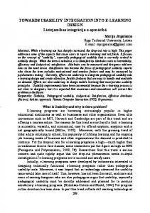
2.2 4D Tetrahedral Mesh Since the tetrahedron, a 3-simplex, is the 3D counterpart to the triangle, a 2-simplex, a mesh composed of tetrahedra is a natural extension of the triangular mesh model commonly found in 3D computer graphics. A 4D object can be approximated by a tetrahedral mesh that represents the boundary of the hypersurface. While this method is only an approximation of the hypersurface, the simplicity of the model lends itself to relatively simple algorithms for visualizing 4D shapes. We can calculate a 4D tetrahedron normal which is a vector that is perpendicular to the tetrahedron. The tetrahedron normal is calculated by generating three vectors from the tetrahedron (see figure 1):
Figure 1: The vertex ordering convention used in Fourveo. Vertices 1, 2, and 3 form the base of the tetrahedron and are arranged counterclockwise when viewed from above. Vertex 0 is the apex of the tetrahedron. This ordering is also used by [15]. The edge ordering convention is also listed.
E1 = v1 − v0, E2 = v2 − v0, E3 = v3 − v0 Using the strategy implemented by [14, 15], we can calculate the tetrahedron normal by finding the determinant of the following matrix and solving for i, j, k, and l: i j k l E1 E1y E1z E1w 4D normal = x E2 E2 E2 E2 x y z w E3x E3y E3z E3w We compose i, j, k, and l into the 4D vector (i, j, k, l). We normalize the resulting vector to get the 4D tetrahedron normal (see figure 2). This tetrahedron normal is a useful tool for our slicing algorithm described in section 3. Previously-existing software for creating 4D geometric shapes is meager and there is none that allows for arbitrary shapes, including Fourveo. The shapes most often featured by 4Dcapable software, including those mentioned in this section, are generated procedurally. This limits us to a small set of simple geometric shapes that are extensions of simple 3D solids. We include three 4D geometric shapes: the Hypercube, the (tessellated) Hypersphere, and the Hypercrystal, a prism with a dodecahedral cross-section.
by [16]. In either method of projection, once the object has been projected to 3D, it can be projected to 2D using standard 3D graphics libraries.
3 Novel Cross-Section Algorithm Figure 2: A triangle with its surface normal (left) and a tetrahedron with its 4D tetrahedron normal, projected to 2D (right).
2.3 Visualizing 4D Geometry Since we inhabit a 3D world and typically use 2D display devices, visualization of 4D geometry in our lower-dimensional world becomes one of the major challenges of 4D animation. In some way, the visualization needs to encode, compress, or remove two dimensions from the data. There are several computer-aided methods for accomplishing this task. The two most commonly-used methods are reviewed below. 2.3.1 3D Cross-Section In the same way that a 2D being might view a 3D object as it passes through the being’s 2D plane of existence, we might similarly view a 4D object passing through three-space. It would appear as an ordinary 3D object, a cross-section of the 4D object, but would appear to change shape and/or topology as it passes through our 3D hyperplane. Generating 3D cross-sections is an appealing visualization method because it depicts hyperdimensional objects as they would appear if they intersected the 3D hyperplane. 2.3.2 Projection Projection is another way to compress 4D geometry into 2D space. After applying any desired transformations to the object (any combination of translation, rotation, scaling, etc.), the geometry can be projected to 3D with either a parallel or perspective projection. In practice, parallel projection to 3D involves simply dropping the w-coordinate of each vertex. Perspective projection from 4D to 3D involves scaling the geometry based on its distance from the viewpoint along the w-axis. It was first implemented
3.1 Preliminary Considerations In the process of creating a 3D animated sequence, several independent pieces of software commonly are used to achieve the final result; exporting data from one piece of software for use by another becomes necessary. Rendering the 4D animation to a sequence of mesh files (.OBJ in this case) allows a user to create a 4D animation, and then transfer the projected or sliced geometry to a conventional 3D package for subsequent work. The cross-section of a tetrahedron embedded in 4D space can be a point, an edge, a triangle, a quadrilateral, or the entire tetrahedron itself (see figure 3). Points and lines are discarded when producing solid, opaque cross-sections (as opposed to wireframe meshes which lack solid faces). Some 3D graphics libraries are able to draw triangles, but not quadrilaterals. The quadrilaterals need to be triangulated into two non-intersecting triangles. By imposing a vertex ordering for the tetrahedron, an ordered list of vertices of the quadrilateral can be generated such that: 1) the quadrilateral is not a complex polygon and 2) the quadrilateral is convex. Such a quadrilateral is then trivial to triangulate. Another issue to consider is front- and backfacing polygons, which generally depends on the winding order of the vertices in a triangle. Since we intend to transfer scene geometry to other animation software and cannot depend on the rendering algorithms used in each software package to provide all the needed features in an appropriate form, we need to enforce a consistent vertex winding order in the crosssection geometry. This winding order is needed not only for rendering, but also for saving the cross-sections to secondary storage since other software will expect a consistent winding order. Figure 4 demonstrates the potential visual errors caused by inconsistent winding order. Given a 4D tetrahedral mesh with consistent outward-facing tetrahedron normals, we can en-
Figure 3: All possible tetrahedron slice configurations: a) a triangular slice which intersects three edges, b) a quadrilateral slice which intersects four edges, c) a triangular slice that perfectly intersects a single face of the tetrahedron, d) a triangular slice that intersects the tetrahedron vertex-first, and e) a triangular slice that intersects the tetrahedron edge-first. An additional configuration, where all four triangular faces intersect the 3D hyperplane, is not pictured here.
Figure 4: The cross-section of a hypercube with inconsistent winding order (left) and consistent winding order (right). The apparent holes in the mesh are due to backface culling.
Figure 5: An overview of the novel slicing algorithm representing the steps taken to slice a single tetrahedron. These steps are repeated for each tetrahedron in each mesh.
force a consistent vertex winding order in the resulting slice polygons. For each tetrahedron that is intersected by the 3D hyperplane, we calculate its 4D tetrahedron normal and project it to the 3D hyperplane (in practice, we simply drop the w-coordinate). We take the intersection of the tetrahedron (a triangle or quadrilateral) and generate a 3D surface normal assuming a counterclockwise vertex order. We then calculate the dot product of this surface normal and the projected 4D tetrahedron normal. If the dot product is negative, the vertex order is incorrect and we need to reverse it; once reversed, the vertices will be stored in counterclockwise order, the de facto standard winding order in most 3D animation software. Figure 5 outlines the steps of the novel slicing algorithm for a single tetrahedron. For the full details of the algorithm, refer to the supplementary materials for this paper.
4 General-Purpose Animation in 4D 4.1 Affine Transformations A transformation in 4D is represented by a 5x5 matrix and a homogeneous point in 4D is represented by a 5D vector. The method for applying nested transformations to 4D objects in a hierarchical structure is nearly identical to that of 3D hierarchical structures. Nested transformations in 4D allow for parent-child relationships between 4D objects. The translation and scaling transformations extend to 4D in a straightforward manner. The added dimension simply adds another coordinate value for the w-axis. Likewise, the transformation matrices extend easily to 4D. The matrices simply have an extra row and column for the added w-axis. Rotation commonly is thought to happen around an axis, but actually happens in perpendicular planes. The confusion exists because in 3D there are three mutually perpendicular axes and three planes of rotation, each of which is perpendicular to exactly one axis. However, in 4D, by listing all possible combinations of any two axes, we find that there are six planes of rotation. The rotation transformation, therefore, must contain orientation values for each of the six planes of rotation. Uniform shearing, while not generally used as an animation technique in 3D animation software, is included for the sake of completeness. Shearing in 4D is identical to shearing in 3D, except that we have more dimensions on which to base shearing.
4.2 Projected Markers When visualizing 4D geometry with the crosssection visualization method, a visible crosssection exists only if the 4D hypershape intersects the 3D hyperplane; if none of the elements of a 4D shape intersect the hyperplane, there is no visible cross-section. Without a visible cross-section, the animator is unable to visually determine where the hypershape is located or where a cross-section will appear once the hypershape returns to the hyperplane. See figure 6 for the analogue of this problem in 3D.
While this disappearing and reappearing phenomenon is a characteristic of interacting with lower-dimensional spaces, the animator is at a distinct disadvantage without some other visual indicator of the 4D position of the hypershape he is animating. To alleviate this problem, and to bring more intuition to 4D animation, we introduce the concept of Projected Markers. A projected marker represents the centroid of a 4D shape, projected onto a 3D hyperplane. A point is placed at the centroid of a 4D shape. This point is then projected parallel to the 3D hyperplane. At this projected point in 3D space, we place a small sphere to mark its position. The sphere’s maximum radius is 0.15 units; it is large enough to be seen easily, but small enough so as not to obscure most cross-sections. If the animator desires, he can hide these markers. The position of the 4D centroid relative to the hyperplane is color-coded. If the centroid is ”above” the hyperplane (i.e. its w-coordinate is greater than 0), the marker is colored red. If it is ”below” the hyperplane (i.e. its w-coordinate is less than 0), the marker is colored blue. If it is on the hyperplane (i.e. its w-coordinate is equal to 0), the marker is colored white. To ensure that the marker is visible regardless of the color of the object, the marker has a dark outline. As an object moves about 4D space, the projected marker moves correspondingly on the 3D hyperplane (see figure 7). The marker is scaled according to the distance between the centroid and the hyperplane. In most cases the cross-section appears close to the projected marker1 . Additionally, the animator can quickly determine in which direction to translate a 4D shape to cause it to intersect the hyperplane and create a cross-section. This gives the animator more facility in animat1
If the 4D shape is significantly larger along some axis than along its other axes and the object is oriented such that the larger extension is nearly parallel to the hyperplane, its first cross-section will appear far from its centroid. As a lower-dimensional analogy, imagine holding a pencil above a pool of water, nearly parallel to the water’s surface, and lowering it. The point where the pencil first intersects the water’s surface may be relatively far from the pencil’s centroid. In both cases, as the object passes through the hyperplane or plane, the cross-section first moves rapidly toward the centroid, and then rapidly away from the centroid, providing insight into the object’s shape.
Figure 6: A 3D analogue of Projected Markers. Figure 8: The 4D translation widget with no rotation (left) and some rotation (right). The scaling widget is identical, except that the handles use cubes to denote the scaling operation. 4.3.1 Interactive Translation and Scaling Figure 7: Several projected markers for 4D shapes.
ing 4D shapes, especially when the shapes move away from the hyperplane.
4.3 4D Interactive Transformation Widget Interactive transformation allows an animator to translate, rotate, or scale an object quickly and without having to enter a value numerically. This is a desirable feature when it is more important to set multiple values quickly than it is to set exact values. Most 3D animation packages implement a comparable feature [17, 18, 19, 20, 21, 22, 23]. Interactivity also facilitates the development of intuition [24]. We have developed an interactive transformation widget which allows the animator to adjust the position, orientation, and size of a 4D object in 4D space2 . The widget adapts the conventions of 3D transformation widgets, namely, color-coded control handles with specific shapes to indicate the type of transformation. 2
While Fourveo supports animation of uniform shearing, we did not implement an interactive shearing widget. This follows the conventions of many 3D animation packages which, similarly, do not implement an interactive shearing widget.
Since the appearance and use of the translation and scaling widgets are nearly identical, they are combined in this section with their differences explained. As seen in figure 8, the widgets include four color-coded handles which correspond to the four principal axes: red for x, green for y, blue for z, and yellow for w. Each handle has a shape which indicates both the direction of the handle and the type of transformation. Conventionally, a cone denotes translation and a cube denotes scaling. The direction of each handle is determined by multiplying each principal axis by the object’s rotation matrix, then parallel-projecting each to 3D. The length of each handle is determined by its orientation relative to the 3D hyperplane. A short handle is a visual cue that the axis is perpendicular or nearly perpendicular to the 3D hyperplane. 4.3.2 Interactive Rotation The rotation widget follows a similar colorcoding scheme, but the handles are circles. Recall from section 4.1 that there are six rotation planes in 4D. The color-coded rotation planes are as follows: red for yz, green for xz, blue for xy, yellow for xw, cyan for zw, and magenta for yw. The colors for the yz, xz, and xy planes match color conventions of 3D animation software. Colors for the xw, yw, and zw planes are arbitrary. Each rotation plane is represented by a circle. For each handle, 32 vertices are arranged in a circle on the corresponding rotation plane. The vertices are rotated to match the orientation
package and to apply effects such as shading, lighting, texture, and photorealistic rendering. It also enables him to combine 4D animated objects with traditional 3D animation, where 3D objects react to 4D objects.
5.2 Animating 3D/4D Interactions Figure 9: The 4D rotation widget with no rotation (left) and some rotation (right). of the 4D object, and then are projected to the 3D hyperplane. The projection of the circle in 3D will be either a perfect circle, an ellipse, or a line segment, depending on its orientation. A perfect circle indicates that the particular rotation plane is parallel to the 3D hyperplane while a line segment indicates that the particular rotation plane is perpendicular to the 3D hyperplane. This visual cue informs the animator of the orientation of the object in 4D (see figure 9).
4.4 Keyframe Animation in 4D Keyframe animation is extended to 4D by [13]. The extension of keyframe animation from 3D to 4D simply adds an extra principal axis, w, to translation, scaling, and shearing, and adds three planes of rotation: xw, yw, and zw. Our system also extends the animation curve editor commonly found in conventional 3D animation software.
5 3D/4D Animation Workflow 5.1 Integrating 4D Animation into a 3D Animation Workflow Most 3D animation software allows some sort of data exchange via geometry export/import operations. We allow the animator to export the animation to a series of 3D Wavefront .OBJ files, where the visualization at each frame in the timeline is represented by a single .OBJ file. The Wavefront OBJ file format is a nearly ubiquitous format and often is used for exchanging geometry between 3D software packages. By exporting a 4D animation into this format, the animator is able to import it into nearly any 3D animation
The animator may want to create an animation which contains both 3D and 4D objects and in which the 3D and 4D objects interact with each other, both directly and indirectly. In this scenario, the 4D objects are transformable in 4D space while the 3D objects are restricted to transformation in 3D space. Hypothetically, a 4D object can apply forces on a 3D object such that the 3D object transforms in 4D space. The 3D object, however, can apply forces on a 4D object such that the 4D object transforms only in 3D space. The animator can begin both 3D and 4D modeling and animation simultaneously if they are independent of each other. However, if they are dependent upon each other, the workflow may include several steps of animation in both 3D and 4D software until a desired result is achieved.
5.3 4D Tetrahedral Mesh File Format While Fourveo can generate several simple 4D shapes, the animator may want to import different arbitrary 4D shapes for use in his animations. We describe a simple 4D geometry file format for data exchange between this and future 4D systems. The file format is inspired by the Wavefront OBJ format for 3D geometry. The format assumes a mesh composed of tetrahedra and allows 3D texture coordinates and 4D tetrahedron normals. See the supplementary materials for this paper for the full details of this file format.
6 Conclusion 6.1 Results Several animations were created with Fourveo to demonstrate that it can be included in a 3D animation workflow. This section describes four of those animations. Blender is the 3D animation software used in these
Figure 10: Walk through Walls in the Fourth Dimension
Figure 13: Hypercube Perspective Projection
6.2 Conclusions
Figure 11: Ball Bouncing on Hypercube
examples. All 4D objects were animated in Fourveo, exported as OBJ sequences, then shaded, illuminated, and rendered in Blender. Screenshots of these animations are in figures 10, 11, 12, and 13. These animations may be viewed by visiting the following links: https://youtu.be/3nlVMNFJ8tw, https://youtu.be/-7npAL_9lKg, https://youtu.be/ENm7Uo7B4M8, and https://youtu.be/C0pujDYCJpo.
Figure 12: Hypercube projection
cross-section
inside
All our objectives were achieved in the process of designing and implementing Fourveo. Both the logical and graphical interfaces to conventional 3D animation software have been shown to extend to 4D. The aim of this specific extension is to lessen the learning curve associated with 4D space and geometry. To achieve this, we sought to maintain the 3D animation paradigm, including object manipulation, file format, and keyframe animation. Interactivity with 4D objects, using the 4D interactive transformation widget and projected markers, enhances intuition of 4D objects. The 4D transformation widget facilitates interactivity and creates a tight feedback loop for the animator.
6.3 Future Work Fourveo facilitates and invites the development of meaningful, specialized features which are beyond the intended scope of the work reported here. 4D Skeletal Animation: 3D animated characters commonly are animated with the 3D skeletal animation technique. 4D animated characters could be animated with the extension of this technique. 3D skeletal animation depends on quaternion rotation to rotate bones about arbitrary lines. Quaternion rotation works for 3D rotation, but needs to be extended to 4D rotation to facilitate 4D skeletal animation. This feature was not implemented because of the limited selection of simple 4D shapes provided by Fourveo and the absence of software for creating arbitrarily-complex 4D shapes. The simple shapes provided do not require the implementation of a 4D skeletal animation system.
Tighter Integration with 3D Animation Software: Fourveo’s OBJ sequence export feature allows it to be used with almost any 3D animation software, but introduces the timeconsuming step of exporting then importing the sequence. Fourveo can be extended to integrate with 3D animation software in one of two ways: first, as a plugin for a specific 3D animation package and second, as a standalone system, but with plugins to exchange geometry and animation data between itself and the intended 3D animation system. The paradigm we have implemented has a more time-consuming workflow, but offers the greatest versatility because of the universality of the Wavefront OBJ file format. Whereas versatility has been a priority in our work, those who require a faster workflow may choose to implement one of the other paradigms discussed in this section.
Acknowledgements This research was funded by the Department of Computer Science and the College of Physical & Mathematical Sciences at Brigham Young University, and by a generous donation from an anonymous, former member of the Brigham Young University Hyperdimensional Research Group. We are grateful for the reviewers’ guiding remarks.
References [1] Edwin A Abbott. Flatland: A romance of many dimensions. OUP Oxford, 2006. [2] Henry P Manning. The Fourth Dimension, Simply Explained. Dover Publications, 1960. [3] Randall Munroe. Flatland. https:// xkcd.com/721/, 2010. [Online; accessed 10-November-2014]. [4] Daniel Wilding. Four-dimensional data navigation. Master’s thesis, Brigham Young University, 2007. [5] Paul L Isaacson. Computer graphic presentation of hypothesized four-dimensional phenomena. Master’s thesis, Brigham Young University, 1984.
[6] A Michael Noll. Computer animation and the fourth dimension. In Proceedings of the December 9-11, 1968, fall joint computer conference, part II, pages 1279– 1283. ACM, 1968. [7] Gordon Kindlmann. Polytope visualization: Peek. http://www.cs.utah. edu/˜gk/peek/, 2000. [Online; accessed 2-June-2015]. [8] Wolfram. Wolfram language & system documentation center. http://reference.wolfram. com/language/, 2015. [Online; accessed 16-July-2015]. [9] Mathworks. Matlab documentation. http://www.mathworks.com/ help/matlab/, 2015. [Online; accessed 19-April-2015]. [10] POV-Ray. Pov-ray for unix version 3.7 documentation. http://www. povray.org/documentation/ 3.7.0/, 2013. [Online; accessed 20-May-2015]. [11] Robert Webb. Stella4d manual. http://www.software3d. com/StellaManual.php?prod= stella4D, 2014. [Online; accessed 14-April-2015]. [12] Paul Bourke. Hyperspace, user manual. http://paulbourke.net/ geometry/hyperspace/, 1990. [Online; accessed 7-April-2015]. [13] Andrew J Hanson, Konstantine I Ishkov, and Jeff H Ma. Meshview: Visualizing the fourth dimension. Overview of the MeshView 4D geometry viewer, 1999. [14] Steven R Hollasch. Four-space visualization of 4 d objects. Master’s thesis, Arizona State University, 1991. [15] Alan Chu, Chi-Wing Fu, Andrew J Hanson, and Pheng-Ann Heng. Gl4d: A gpubased architecture for interactive 4d visualization. IEEE transactions on visualization and computer graphics, 15(6):1587– 1594, 2009.
[16] A Michael Noll. A computer technique for displaying n-dimensional hyperobjects. Communications of the ACM, 10(8):469– 473, 1967. [17] Autodesk. 3ds max help. docs.autodesk.com/3DSMAX/15/ ENU/3ds-Max-Help/index.html, 2013. [Online; accessed 15-May-2015]. [18] Autodesk. Maya user’s guide. download.autodesk.com/ global/docs/maya2014/en_ us/index.html, 2014. [Online; accessed 15-May-2015]. [19] Autodesk. Softimage user’s guide. download.autodesk.com/ global/docs/softimage2014/ en_us/userguide/index.html, 2014. [Online; accessed 15-May-2015]. [20] Blender Foundation. Blender manual contents. https://www.blender.org/ manual/, 2015. [Online; accessed 3March-2015]. [21] The Foundry. Modo online help. https://help.thefoundry. co.uk/modo/901/, 2015. [Online; accessed 10-May-2015]. [22] Maxon. Cinema 4d quickstart documentation. www.maxon.net/support/ documentation.html, 2015. [Online; accessed 20-May-2015]. [23] Side Effects Software. Houdini 14.0. www.sidefx.com/docs/ houdini14.0/, 2015. [Online; accessed 20-May-2015]. [24] Edward G Britton, James S Lipscomb, and Michael E Pique. Making nested rotations convenient for the user. In ACM SIGGRAPH Computer Graphics, volume 12, pages 222–227. ACM, 1978.