I f you pay attention to detail differences on your freight cars, you owe the same attention to the trucks. Under-standing how railroad trucks evolved will help you ...
Modeler’s guide to
freight car trucks Understanding and modeling trucks and wheelsets By Jeff Wilson • Photos by the author
I
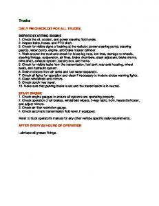
f you pay attention to detail differences on your freight cars, you owe the same attention to the trucks. Understanding how railroad trucks evolved will help you choose the proper ones for your models. Figure 1 shows the parts of a freight car truck. Railroads have used hundreds of different truck designs over the years. We can’t show them all, but we can present an overview of trucks commonly used from the early 1900s through today. The freight car rides on its bolster, held by a kingpin on the car’s bolster that extends into a hole in the middle of the truck bolster. The truck bolster isn’t solidly attached to the sideframe – it “floats” on a group of springs (five or more, called the spring package) in each sideframe. The size and number of springs varies based on the capacity of the truck. These springs cushion the ride by allowing the bolster to move up and down in the sideframes and provide equalization by allowing the sideframes to rotate around the bolster. The sideframes, in turn, place their load on the ends of the axles. Older trucks, such as the one in fig. 1, are known as
FIG. 1 TYPICAL FREIGHT TRUCK
Center plate
solid-bearing trucks (often incorrectly called friction bearings). In these the journal box surrounds the bearing and axle end, the “journal.” The journal box is packed with a fibrous cotton material – called waste – soaked in lubricating oil. The journal and bearing surfaces are lubricated by wicking oil from the waste. Later trucks used roller bearings that roll with much less friction and require no added lubrication. Trucks are classified by weight. The rating isn’t the load a single truck can carry, rather it is the total load of the car. A 50-ton truck is designed for a 50-ton-capacity car, and so on. In the early 20th century most cars were in the 30- to 40ton range; most modern steam-era cars had 50- and 55-ton capacities. The 1950s saw covered hoppers and boxcars of 70-ton capacity, moving to 100-ton jumbo covered hopper, tank, and coal cars in the 1960s. Some modern cars, notably articulated intermodal well cars, use 125-ton trucks, but many modern cars are 70-ton cars. On the following pages we will take a look at how trucks changed over time and how they can be modeled.
Brake shoe Sideframe
Axle
Bolster
Flange
Brake hanger Brake lever
Wheel tread
Wheel face
Springs Brake beam
Journal box
72
MODEL RAILROADER
•
modelrailroader.com
Archbar and Andrews trucks The most common trucks used in the early 1900s were archbar trucks as shown in fig. 2. These were made of pressed steel and bar components that were bolted together. Although they worked well, archbar trucks required a lot of maintenance. Their bolts needed frequent tightening, as they tended to work loose with the shocks and jolts of operation. Although some archbar trucks were built into the 1920s, they had largely been superceded by more advanced designs by the mid-teens. Archbar trucks were banned from interchange service starting Dec. 31, 1939. A “recovery period” was allowed until June 1, 1940, permitting cars with archbar trucks to return empty to their owners.
Trucks with cast sideframes were the next major development, eliminating the problems of the bolts and connectors of the archbar truck. The most popular of these early cast trucks was the Andrews, shown in fig. 3. Andrews trucks still used separate journal boxes, and could be identified by the steel bar between the truck sideframe and the journal box base. Andrews trucks were in production from around 1910 through the 1930s. A big selling feature of the Andrews design was that journal boxes from older archbar trucks could be reused in new Andrews trucks. Figure 3 also shows the truck side bearings, mounted inward slightly, just above the spring package. These provide stability for the car on the bolster.
Fig. 2 ARCHBAR TRUCK. Archbar trucks are made of numerous pieces of pressed steel and bar components bolted together. The trucks worked well, but the bolts tended to loosen over time. They were banned from interchange service starting December 31, 1939.
Fig. 3 ANDREWS TRUCK. These trucks have cast steel sideframes with journal boxes bolted in place. The steel retaining straps extending from the base of the journal box to the sideframe identify this an an Andrews truck. This one was built by the Bettendorf Co.
Bettendorf, AAR trucks
many builders made trucks of this type. The U-section cast steel truck was eventually adopted as an ARA (American Railway Association; later AAR (American Association of Railroads) standard: the Type Y truck. Each of these trucks follows the AAR standard, but many have varying details including sideframe shape, spring size and styles, bolster design, and journal-box lids. The double-truss sideframe of the 1930s improved the AAR standard. The sideframe is similar in appearance to earlier trucks, but parts of the U-shaped section are filled in, creating the effect of a double-layer sideframe on each side. A truck of this type is shown in fig. 6.
The next generation of trucks featured journal boxes cast as integral parts of the sideframe. The Bettendorf Co. was the first to do this (as early as 1903), using a cast sideframe with a “T” cross section, an example is shown in fig. 4. The Bettendorf T-section truck was popular through the teens. Significantly stronger trucks featuring a U-shaped crosssection eventually superceded the T-section trucks. Figure 5 shows an example. This truck, which is most identified with the modern steam and early diesel eras, has become known generically – and incorrectly – as the Bettendorf truck. The Bettendorf Co. widely licensed elements of its design, and
Fig. 4
Fig. 4 BETTENDORF T-SECTION TRUCK. The first cast Bettendorf trucks had T-shaped cross sections and a unique sideframe profile. Fig. 5 AAR U-SECTION TRUCK. Trucks with U-shaped sideframe cross sections were built by several companies. The modified sideframe was stronger than the older T-section truck design. Fig. 6 DOUBLE-TRUSS TRUCK. Compare the sideframe of this ASF double-truss truck to the one in fig. 5. This sideframe also has a vertical stabilizing snubber in place of one of the coil springs.
Fig. 5
Fig. 6
DECEMBER 2003
•
MODEL RAILROADER
73
Improving the standard After double-truss and U-section cast-sideframe trucks proved to be sufficiently strong for the loads they carried, manufacturers turned their attention to improving the riding characteristics of their trucks by cutting down on excess lateral and vertical movement. An early (1920s) attempt at improving riding quality was the Dalman truck. This truck had eight springs in each sideframe (compared to five on other trucks), with springs on different levels. As fig. 7 shows, this, along with a unique sideframe, gave Dalman trucks a distinctive appearance. The two most popular improved trucks came along a bit later: the Barber S-2, which is shown in fig. 8, and the American Steel Foundries (ASF) A-3 Ride Control, shown in fig. 9. Both designs were introduced during World War II, and were advertised to ride more smoothly, cut down on wheel and spring wear, and be easier on track and roadbed. The A-3 caught on rapidly and became the most popular truck in use through the end of the solid-bearing era.
Many other stabilized trucks were introduced, including the National B-1. Figure 10 shows this truck, which had a unique spring package featuring stabilizing wedges. The Allied Full Cushion truck shown in fig. 11 was used extensively from World War II through the mid-1950s in high-speed service – mainly express boxcars and troop sleepers. This distinctive-looking and complex truck rode quite smoothly, but it eventually earned a reputation for derailing. Because of this, the Allied Full Cushion was banned from interchange service in 1955. Cabooses were often equipped with trucks that were smoother riding than those used on standard freight cars. Improved ride quality was also the reason why caboose trucks generally had elliptical “leaf” springs in place of coil springs, a design choice made possible because a caboose has a relatively constant weight. The Barber-Bettendorf Swing Motion caboose truck was among the most popular in the solid-journal era. An example of this truck is shown in fig. 12.
Fig. 7 DALMAN TRUCK. Eight springs (most trucks have five) mounted on different levels made the Dalman truck design distinctive. This Dalman truck was made by American Steel Foundries (ASF).
Fig. 8 BARBER S-2 TRUCK. The Barber Stabilized truck design was among the most commonly used types of freight car trucks through the end of the solid-bearing-truck era.
Fig. 9 ASF A-3 RIDE CONTROL TRUCK. This truck became the most popular truck of the post-World War II era.
Fig. 10 NATIONAL B-1 TRUCK. This truck can be distinguished from others by its unique spring package and sideframe design.
Fig. 11 ALLIED FULL CUSHION TRUCK. The Full Cushion was a complex truck with a very distinctive appearance, with springs outboard each journal instead of under the bolster ends.
Fig. 12 CABOOSE TRUCK. The Barber-Bettendorf caboose truck had elliptical “leaf” springs for improved ride quality and was initially manufactured with solid bearings.
74
MODEL RAILROADER
•
modelrailroader.com
Roller bearing trucks A problem with solid-bearing trucks is that the journal boxes need frequent lubrication. This was labor intensive, and a dry bearing would cause an overheated journal, which could result in a fire or broken axle and consequent derailment. Roller-bearing journals were the solution. Roller bearings reduced friction and did not require additional lubrication. Roller-bearing trucks have been around since the turn of the 20th century and began to see common use in the 1930s on passenger cars. Because of their additional cost, the trucks weren’t widely used on freight equipment until the late 1950s and 1960s. The end caps on the journals, as shown in fig. 13, identify these trucks. New cars built after 1966 were required to have rollerbearing trucks, and solid-bearing trucks were banned from interchange service after 1980.
The two most popular modern trucks are the ASF Ride Control, shown in fig. 14, made by ASF-Keystone, and the Barber S-2, made by Standard Car Truck Co., shown in fig. 15. Both date back to solid-bearing designs. Other common modern trucks include the ASF Ridemaster and National C-1 (not shown). Each is made with various spring packages and other options in 70- to 125-ton versions. The Barber-Bettendorf Swing Motion caboose truck is one most commonly used on modern cabooses and is quite similar to the solid-bearing version, as fig. 16 shows. Identifying the proper truck for modeling purposes can be difficult. Features can differ even within specific truck styles, including the roller-bearing end-cap design and springs. The manufacturer’s name and truck type are cast on the sideframe and that’s the easiest way to identify any truck. If all else fails, matching the sideframe design will get you close.
Fig. 13 ROLLER-BEARING TRUCK. This 70-ton ASF Ride Control truck shows the roller-bearing end caps. The roller bearing assemblies take the place of the journal boxes.
Fig. 14 100-TON RIDE CONTROL TRUCK. The 100-ton version of the ASF Ride Control truck has three visible springs. Note the differing styles of bearing end caps on each axle.
Fig. 15 100-TON BARBER S-2 TRUCK. Modern freight car trucks are similar in appearance, but if you look carefully, this S-2 truck has subtle differences in shape compared to the Ride Control truck.
Fig. 16 BARBER-BETTENDORF CABOOSE TRUCK. The most popular modern-era caboose truck was the roller-bearing-equipped version of the venerable Barber-Bettendorf truck.
STEEL WHEELS A-ROLLIN’
W
heels on prototype cars have a number of differences, but for modelers the most important detail is probably the size. The 33"-diameter wheel is standard on freight equipment of 70-ton capacity and under. For 100-ton trucks, 36" wheels are used, and for 125-ton trucks (as on some articulated intermodal cars), 38" wheels. An exception is that smaller wheels (28" diameter) are used on triple-deck auto-rack cars. This allows these 70-ton cars to negotiate tighter clearances. Ribs on the back of the wheels are a detail found on many model wheelsets. Ribs were a characteristic of many castiron wheels (known as “chilled” wheels for
the heat treatment of the treads). The ribs dissipated the heat generated during braking. Chilled wheels faded from use in the 1950s, were forbidden on new cars after 1957, and were banned from interchange use as of 1970. Modern wheels are cast or wrought steel and do not have ribs. Steel wheels began increasing in popularity starting in the mid-1920s, and by the end of the steam era most cars used steel wheels instead of chilled wheels. Steel wheels on freight cars are either single-wear or two-wear. This information (1W or 2W) is usually stenciled on the car end. Single-wear wheels are scrapped after the tread profile wears to a certain point. Two-wear wheels have thicker (2") rims and can be recut and reshaped to return
the wheel to its proper contour. Single-wear wheels are cheaper, while double-wear wheels will pay for themselves on heavy-duty cars where the wheels will be turned during the life of the car. – J. W.
RIBBED-BACK WHEEL. Heat-dissipating ribs on the back of the wheel were a characteristic of many “chilled” cast-iron wheels.
DECEMBER 2003
•
MODEL RAILROADER
75
Model trucks and wheels Most model trucks have sideframes made of acetal plastic; Kadee and some others are die-cast metal. Wheelsets generally have needlepoint axles that ride in pockets behind the molded journal box or roller-bearing end cap. The chart lists the most-used prototype freight-car trucks. Wheels can be either plastic or metal. Most experienced modelers prefer metal wheels. Metal wheels look more realistic because their treads can shine. They also have a polishing effect on the track, and they even sound more realistic. In HO scale the National Model Railroad Association standard calls for a wheel width of .110" (tread plus flange). Some modelers have begun using so-called semi-scale wheels, with a width of .088", shown in fig. 17. InterMountain, NorthWest Short Line, ReBoxx, and others make these. Thinner wheels look more realistic, and will still negotiate most ready-made trackwork. Wheels made to Proto:87 dimensions range from .069" to .064".
Model trucks in HO are either rigid or sprung. Rigid trucks have non-functioning springs molded into the sideframe. Sprung trucks work like scaled-down prototype trucks, with a bolster that rides atop actual metal springs in the sideframes. The theory is that sprung trucks, because each sideframe can independently move, allow wheels to follow imperfections in the track better than rigid trucks. However, if your trackwork is solid, it doesn’t matter which truck type you choose. Some modelers feel that sprung trucks look very realistic; others think that the profile of the real metal springs is too delicate looking and that trucks with molded springs look better. Choose the trucks that you think are the most realistic. Trucks in N scale are rigid. Most come with plastic wheels with deep-profile flanges, although there has been a trend lately toward shallow (usually called low-profile) flanges, as shown in fig. 18. These operate well and look more realistic than wheels with deep flanges. 1
This Kato HO Barber S-2 truck features roller-bearing end caps that actually rotate.
Fig. 17 HO SEMI-SCALE WHEELS. InterMountain’s semi-scale .088" wheels (right) are noticeably narrower than Kadee’s HO scale National Model Railroad Association RP25 .110" wheels (left).
These Accurail Andrews HO trucks have single-piece acetal plastic wheelsets.
Kadee T-Section Bettendorf HO trucks have real metal springs.
Fig. 18 N SCALE SHALLOW-FLANGE WHEELS. Micro-Trains Barber trucks now come with both standard- and shallow-flange wheels.
Athearn’s HO 70-ton ASF Ride Control roller-bearing truck.
Life-Like made this HO National B-1 solid-bearing truck.
InterMountain produced this HO ASF A-3 solid-bearing truck.
Kadee’s HO scale archbar truck models an older style of truck.
Atlas’ HO Barber-Bettendorf caboose roller-bearing truck.
N scale SOLID-BEARING TRUCKS Mfr.
76
Archbar
ROLLER-BEARING TRUCKS Andrews
ARA, AAR
Atlas
22050 22051*
InterMountain
60001••, •
MicroTrains
1010• 1011 1012•
Model Die Casting
8984••
MODEL RAILROADER
1051 1052• 1053•
1000• 1001 1002• 8983••
•
modelrailroader.com
Allied Full Cushion
BarberBettendorf caboose
70-ton roller-bearing
100-ton roller bearing
22060
22055 22056*
22070 22071* 60011••, •
1190•
302140
1030• 1031 1032• 8980••
1035• 1036 1037• KEY: • = Truckmounted coupler •• = Kit
HO trucks
SOLID-BEARING TRUCKS Mfr.
Archbar
Accurail
Andrews
Vulcan doubletruss
Bettendorf ARA, AAR T-section
103
90400
Atlas
185000
Con-Cor
99250 99251 9066 ∞ 9067 ∞
9068 ∞
9053 ∞
InterMountain Kadee
501* 503*•
509* 510*•
515* 516*•
511* 512*•
500* 502* •
National B-1
Allied Full Cushion
BarberBettendorf caboose
9061 ∞
9057 ∞
9043 ∞
9051 ∞
504* 31601
Life-Like
21251 21253 2902 2922
Old Pullman On-Trak
Dalman
40061
Kato
MDC
ASF Ride Control
100
Athearn
Eastern Car Works
50-ton spring plankless
21254 21255
2903 2923 40011* 40061*
40001* 40081*
5304
Red Caboose
5007 5012 ∞
Tichy Train Group
3002
3012
Walthers
1002* 1010 1018
1004*
5004 5011 ∞ 3008 1003* 1011 1009
1001* 1012 1008
ROLLER-BEARING TRUCKS Mfr.
BarberBettendorf caboose
70-ton rollerbearing
100-ton rollerbearing
70-ton 100-ton 70-ton 100-ton Barber S-2 Barber S-2 ASF ASF Ride Control Ride Control
Accurail
102
Athearn
90397
Atlas
190000
T
here were many manufacturers of freight car trucks from the steam era through the 1950s, including American Steel Foundries (ASF), Bettendorf, Buckeye, Symington-Gould, and others. Reading the information cast into the sideframe is the best way to identify the maker and truck type. Information generally includes the manufacturer, type, spring package, other foundry information, and sometimes the railroad for which the truck was built. – J. W.
4599
195000
Con-Cor Eastern Car Works
4598
90401 180000
9064 ∞
99200 99220
99221
9054 ∞
9070 ∞
InterMountain
40001 40060
Kadee
513*
Kato
518* 31602
Life-Like
IDENTIFYING PROTOTYPE TRUCK MANUFACTURERS
21256
MDC
2918
Old Pullman
40021* 40091*
40031*
Walthers
1005*
1013
KEY: * Sprung ** Less wheelsets • Truck-mounted coupler •• Kit ∞ Kit, less wheelsets Blue = metal wheels
Photo credits: fig. 1, Buckeye Steel Castings; figs. 4 and 6, David P. Morgan Library Collection; fig. 8, Jerry A. Pinkepank; fig. 9, Lee Langum; fig. 10, National Malleable & Steel Castings Co.; fig. 11, George Drury
DECEMBER 2003
•
MODEL RAILROADER
77