and security of future optical communication networks and computing systems. ..... ness for non-classical applications such as quantum cryptography [32] and ...... [178] M. B. Nasr, S. Carrasco, B. E. A. Saleh, A. V. Sergienko, M. C. Teich, J. P..
Frequency conversion in nonlinear optical waveguides: from classical to quantum applications
A thesis submitted for the degree of Doctor of Philosophy of Australian National University
Alexander Solntsev
Declaration
This thesis is an account of research undertaken in the Nonlinear Physics Centre within the Research School of Physics and Engineering at the Australian National University between May 2009 and April 2013 while I was enrolled for the Doctor of Philosophy degree. The research has been conducted under the supervision of A/Prof. Andrey A. Sukhorukov, A/Prof. Dragomir N. Neshev, and Prof. Yuri S. Kivshar. However, unless specifically stated otherwise, the material presented within this thesis is my own. None of the work presented here has ever been submitted for any degree at this or any other institution of learning.
Alexander Solntsev
Publications
†
Journal articles
[1] A. A. Sukhorukov, A. S. Solntsev, S. S. Kruk, D. N. Neshev, and Y. S. Kivshar, "Nonlinear coupled-mode theory for periodic plasmonic waveguides and metamaterials with loss and gain," submitted for publication, http://arxiv.org/abs/1309.2807 [2] A. Sergeyev, R. Geiss, A. S. Solntsev, F. Schrempel, E.-B. Kley, T. Pertsch, and R. Grange, "Second-harmonic generation in lithium niobate nanowires for local fluorescence excitation," Optics Express, 21, 19012 (2013) [3] D. M. Markin, A. S. Solntsev and A. A. Sukhorukov, "Nonlinear waveguide arrays for discrete orbital-angular-momentum-entangled biphoton state generation," Physical Review A, 87, 063814 (2013) [4] A. A. Sukhorukov, A. S. Solntsev, and J. Sipe, "Classical simulation of squeezed vacuum in optical waveguide arrays," Physical Review A, 87, 053823 (2013) [5] A. S. Solntsev, A. A. Sukhorukov, D. N. Neshev, and Y. S. Kivshar, "Photon-pair generation in arrays of cubic nonlinear waveguides," Optics Express, 20, 27441 (2012) [6] M. Grafe, A. S. Solntsev, R. Keil, A. A. Sukhorukov, M. Heinrich, A. Tunnermann, S. Nolte, A. Szameit and Yu S. Kivshar, "Biphoton generation in quadratic waveguide arrays: A classical optical simulation," Scientific Reports, 2, 562 (2012) [7] R. Schiek, A. S. Solntsev, and D. N. Neshev, "Temporal dynamics of all-optical switching in quadratic nonlinear directional couplers Temporal dynamics of all-optical switching in quadratic nonlinear directional couplers," Applied Physics Letters, 100, 111117 (2012) [8] A. S. Solntsev and A. A. Sukhorukov, "Combined frequency conversion and pulse compression in nonlinear tapered waveguides," Optics †
The published results that are included in this thesis are typed in bold.
Letters, 37, 446 (2012) [9] A. S. Solntsev, A. A. Sukhorukov, D. N. Neshev, and Y. S. Kivshar, "Spontaneous Parametric Down-Conversion and Quantum Walks in Arrays of Quadratic Nonlinear Waveguides," Physical Review Letters, 108, 023601 (2012) [10] F. Setzpfandt, A. A. Sukhorukov, D. N. Neshev, R. Schiek, A. S. Solntsev, R. Ricken, Y. Min, W. Sohler, Y. S. Kivshar, and T. Pertsch, "Spectral pulse transformations and phase transitions in quadratic nonlinear waveguide arrays," Optics Express, 19, 1942 (2011) [11] A. S. Solntsev, A. A. Sukhorukov, D. N. Neshev, R. Iliew, R. Geiss, T. Pertsch, and Y. S. Kivshar, "Cascaded third harmonic generation in lithium niobate nanowaveguides," Applied Physics Letters, 98, 231110 (2011) [12] A. S. Solntsev, G. K. Kitaeva, I. I. Naumova, and A. N. Penin, "Measurement of the extraordinary refractive index dispersion in the MIR for Mg:Nd:LiNbO3 crystals by the use of quasi-phase-matching in a random 1D domain structure," Applied Physics B, 99, 197 (2010) [13] Y. C. Huang, A. S. Solntsev, T. D. Wang, and W. W. Hsu, "Generation of fs laser pulses from a ps pulse-pumped optical parametric amplifier with a beat-wave seed signal," Optics Communications, 282, 2250 (2009)
Acknowledgements
I would like to thank my exceptional supervisory panel A/Prof. Andrey A. Sukhorukov, A/Prof. Dragomir N. Neshev and Prof. Yuri S. Kivshar for their invaluable guidance at every critical juncture of my PhD project. Many thanks to all Nonlinear Physics Centre staff members and students and to all co-authors for their support and useful discussions. I would like to give personal thanks to my fellow PhD students Wei Liu, Sergey Kruk, Diana Antonosyan and Allen Wu and (current and former) staff members Dr. Aliaksandr Minovich, Dr. Ivan Garanovich, Dr. Artur Davoyan, Dr. David Powell, Dr. Andrey Miroshnichenko, Dr. Ivan Maksimov and Dr. Ilya Shadrivov for giving me great advice and making my PhD journey pleasant and entertaining. Also many thanks to Dr. Frank Setzpfandt, A/Prof. Alexander Szameit and Prof. Thomas Pertsch from the University of Jena and Prof. Roland Schiek from the University of Regensburg for introducing me to German culture, scientific precision and beer. I acknowledge support by the Australian Research Council (ARC), Australian National Computing Infrastructure (NCI), the Centre for Ultrahigh bandwidth Devices for Optical Systems (CUDOS) and the Optical Society of America (OSA). I thank Australian National University for providing a PhD scholarship and multiple travel grants and prizes. Finally and most importantly, many thanks to my beloved wife Olga and to my parents, relatives and friends for their extraordinary encouragement and support.
Abstract
This thesis encompasses a broad area of physics including linear and nonlinear optics, photonics and quantum physics. It combines the phenomena of nonlinearoptical frequency conversion with waveguiding and coupling, taking advantage of new opportunities presented by advances in fabrication technologies of micro- and nano-waveguides. In this dissertation an in-depth analysis of quantum and classical properties of light traveling in nonlinear optical waveguides, directional couplers and waveguide arrays is performed. The concepts of spatial and temporal dispersion, waveguiding in structures with subwavelength dimensions and nonlinear interactions between different frequencies of light are studied both theoretically and experimentally. Some sections of this thesis include development and implementation of novel physical ideas, while other sections are focused on comprehensive experimental and numerical analysis of advanced theoretical concepts. The results presented in this dissertation demonstrate new physical phenomena with potential applications in the areas of telecommunications and quantum information. The research performed in this thesis opens opportunities for frequency conversion with world-leading power efficiency, including operation with ultrashort pulses for a variety of wavelengths to suit a wide range of perspective application requirements. It also shows an approach for simple and energy efficient spatio-temporal optical signal control, which can find applications in next generation telecommunications networks. Furthermore, the results obtained in this dissertation demonstrate the possibility for flexible shaping of quantum statistics of photons generated in photonic waveguiding structures through spontaneous frequency conversion, contributing to the development of integrated quantum circuits. The new methods of frequency conversion in micro- and nano-scale waveguides and optical circuits have potential to advance the performance, energy efficiency, and security of future optical communication networks and computing systems.
Outline
The dissertation is organized as follows. The Chapter 1 of this thesis is a brief introduction into the concepts of nonlinear optical frequency conversion and classical and quantum aspects of waveguiding and coupling. It contains both a compact literature review and some theoretical formulas that are later used in the other Chapters of this dissertation. Since the topic of this thesis is relatively broad, each following Chapter and Section contains a more focused introduction closely relating to the results presented there. The Chapter 2 demonstrates a number of novel theoretical ideas in the area of high-confinement subwavelength-waveguides (often also called nano-waveguides). In this Chapter it is shown that strong nonlinearity and broadband dispersion engineering enabled by the high-confinement nature of nano-waveguides allow for ultraefficient cascaded third harmonic generation [the Section 2.1], and simultaneous frequency conversion and strong pulse compression [the Section 2.2]. The Chapter 3 shows the results of theoretical and experimental investigation of all-optical temporal, spectral and spatial light dynamics in waveguiding structures. It presents world first measurements of pulse reshaping and phase dynamics in quadratic nonlinear couplers [the Section 3.1] and waveguide arrays [the Section 3.2]. The study focuses on cascaded quadratic nonlinearity that can potentially bring enhanced speed and energy savings to ultrafast optical telecommunications. The Chapter 4 is focused on quantum aspects of a particular frequency conversion process taking place in quadratic nonlinear waveguide arrays. The studied process is called spontaneous parametric down-conversion, and it allows for quantumentangled photon-pair generation followed by a subsequent quantum walk. Quantum walks can potentially be useful for ultrafast database search and very efficient simulation of various quantum systems. In this Chapter it is revealed that integrating photon-pair generation with quantum walks in a nonlinear waveguide array offers better scalability and reconfigurability. An analytical model is developed to study this process in the Section 4.2, and the world first experimental results are reported in the Section 4.3.
The Chapter 5 discusses the opportunities opened by higher dimensionality when dealing with spontaneous parametric down-conversion and quantum walks in waveguide arrays. In this Chapter it is shown that classical light in 2D linear waveguide arrays can be used to simulate nonlinearity and quantum statistics of photon-pair generation and quantum walks in nonlinear 1D waveguide arrays [the Section 5.1] and that 2D nonlinear waveguide arrays can be used for clean and efficient generation of orbital-angular-momentum-entangled photon pairs [the Section 5.2]. The former has scalability implications for quantum information, while the later can be useful in quantum communications. The Chapter 6 brings together the nano-waveguide concept studied in the Chapter 2, nonlinear quantum walks developed in the Chapter 4 and nonlinear phasemodulation discussed in the Chapter 3. A numerical model describing the process of integrated photon-pair generation and quantum walks in arrays of cubic nonlinear high-confinement waveguides is developed in the Section 6.1. This scheme incorporates nonlinear phase-modulation-based all-optical quantum state control. The Section 6.2 discusses experimental feasibility of this approach and demonstrates novel ways of statio-temporal pulse control in nano-waveguide arrays. The numerical results show that the developed platform has significant potential for quantum information and optical telecommunications. In the Chapter 7 I draw the conclusions and discuss future opportunities that can be realized by combining the ideas and concepts demonstrated in the Chapters 2 – 6 and developing integrated quantum nano-photopic spatio-temporal circuits, opening new avenues for communication networks and computing systems of the future.
Contents
1 Introduction 1.1 Frequency conversion . . . . . . . . . . . . . . . . . . . . . . . . . . 1.1.1 Optical nonlinearity . . . . . . . . . . . . . . . . . . . . . . 1.1.2 Second harmonic generation and phase-matching . . . . . . 1.1.3 Spontaneous parametric down-conversion . . . . . . . . . . . 1.1.4 Cascaded third harmonic generation and cascaded quadratic nonlinear phase shift . . . . . . . . . . . . . . . . . . . . . . 1.1.5 Cubic nonlinear phase shift, stimulated four-wave-mixing and spontaneous four-wave-mixing . . . . . . . . . . . . . . . . . 1.2 Waveguides and classical applications . . . . . . . . . . . . . . . . . 1.2.1 Dispersion engineering and pulses . . . . . . . . . . . . . . . 1.2.2 Coupled waveguides and waveguide arrays . . . . . . . . . . 1.3 Waveguides and quantum applications . . . . . . . . . . . . . . . . 1.3.1 On-chip integration . . . . . . . . . . . . . . . . . . . . . . . 1.3.2 Quantum walks . . . . . . . . . . . . . . . . . . . . . . . . .
1 1 1 2 4
7 10 10 13 15 15 16
2 Frequency conversion in nano-waveguides 2.1 Second and third harmonic generation in nano-membranes . . . . . 2.2 Pulsed four-wave-mixing in nano-tapers . . . . . . . . . . . . . . . .
19 19 25
6
3 Pulse dynamics induced by cascaded second harmonic generation 31 3.1 Efficient all-optical switching in quadratic nonlinear directional couplers 31 3.2 Spatiotemporal pulse shaping in quadratic nonlinear waveguide arrays 40 4 Spontaneous parametric down-conversion in 1D waveguide arrays 4.1 Nonlinear quantum walks . . . . . . . . . . . . . . . . . . . . . . . 4.2 Analytical model and biphoton spatial statistics . . . . . . . . . . . 4.3 Experimental control of spontaneous parametric down-conversion spectra and photon-pair correlations . . . . . . . . . . . . . . . . .
51 51 55 61
ii
5 Photon-pair generation in waveguide arrays: higher 5.1 Classical simulation: from one to two dimensions . . 5.2 Generation of orbital-angular-momentum-entangled two-dimensional triangular waveguide arrays . . . . .
Contents
dimensions . . . . . . . . biphotons in . . . . . . . .
68 68
6 Spontaneous four-wave mixing in waveguide arrays 6.1 Nonlinear phase shift and photon-pair correlations . . . . . . . . . . 6.2 Pulse dynamics in modulated nano-waveguide arrays . . . . . . . .
86 86 94
77
7 Conclusion and outlook
101
Bibliography
104
Chapter 1
Introduction
1.1 Frequency conversion 1.1.1 Optical nonlinearity In this introduction I will give a general overview of the basic concepts as well as brief analysis of the current state of physical science regarding key aspects of waveguiding frequency conversion. I will provide a common background for the other Chapters and outline how some of the important problems are resolved in this thesis. Every following Chapter and Section will have its own more focused introduction. The field of nonlinear optics was founded in 1961 [14], shortly after experimental demonstration of the ruby laser [15]. In this first frequency conversion experiment a ruby laser was focused into a crystalline quartz sample, and output radiation was spectrally resolved by a quartz prism. The second harmonic (SH) radiation with frequency ωSH = 2ωp , two times larger than the pump laser frequency ωp , was observed and recorded on a photographic plate, see Fig. 1.1.
Figure 1.1: A direct reproduction of the first plate in which there was an indication of second harmonic from Ref. [14]. The wavelength scale is in units of 10 nm. The arrow at 347.2 nm should have indicated the image produced by the second harmonic. Interestingly, during the process of publication the editor thought that the SH signature was a speck of dirt and deleted it, therefore the first nonlinear optical paper was published without graphical demonstration of the main effect.
2
Introduction
Let us now discuss the theoretical description of the process of second harmonic generation (SHG) [16]. When light enters a material, it induces a polarization P . Radiation from a common light bulb induces a polarization that is linearly dependent on light intensity. However for strong coherent laser beams nonlinear effects start to appear, and the polarization P can be represented as Taylor series with respect to electric field E [17]: P (ω) = ε0 [χ(1) E(ω) + χ(2) E(ω1 )E(ω2 ) + χ(3) E(ω1 )E(ω2 )E(ω3 ) + . . . ] |
{z
∼P (1) (ω)
}
|
{z
∼P (2) (ω,ω1 ,ω2 )
}
|
{z
∼P (3) (ω,ω1 ,ω2 ,ω3 )
(1.1)
}
Here χ(1,2,3) are nonlinear susceptibility tensors of the first, second and third order respectively, and ω, ω1 , ω2 , ω3 are the frequencies, between which the energy exchange is possible. The first term P (1) = χ(1) E(ω) is responsible for the polarization-dependant index of refraction n: χ(1) = n2 (ω) − 1. The second term P (2) is non-zero only in crystals without a center of symmetry, such as LiNbO3 [18]. It may be employed for a variety of frequency conversion processes including SHG, which will be discussed in detail in the next Section. The third term P (3) becomes significant when the laser intensity is high and a particular highly nonlinear material is used. Such materials include a range of chalcogenide glasses and semiconductors. If a laser beam is focused into a narrow silicon waveguide, then the third-order nonlinearity P (3) becomes substantial even for laser powers in sub-watt range [19].
1.1.2 Second harmonic generation and phase-matching We will now look at the second order polarization P (2) and SHG in detail. The SHG is a useful tool in a broad range of applications ranging from signal processing [20] to powerful and affordable laser sources at higher frequencies [21]. The coupled-mode equations describing simple collinear SHG can be written as follows [17]: ∂A2ωp ∂z
= i
ωp χ(2) 2 A exp(i∆kz) 2n2ωp c ωp
(1.2)
∂Aωp ∂z
= i
ωp χ(2) A2ωp Aωp exp(−i∆kz) 2nωp c
(1.3)
where ∆k = 2kωp − k2ωp = (2ωp /c)(nωp − n2ωp )
(1.4)
is the so-called phase mismatch between the pump [also called fundamental wave
1.1 Frequency conversion
3
Figure 1.2: (a) Scheme of Second Harmonic Generation. (b) Growth of secondharmonic power along the propagation direction, assuming a constant pump intensity. Solid curve: phase-matched case, with the power growing in proportion to the square of the propagation distance. Dashed curve: non phase-matched case, with the secondharmonic power oscillating between zero and a small value.
(FW)] and second harmonic waves. Here Aωp and A2ωp are the slowly varying electric field envelopes and nωp and n2ωp are the refractive indices for the pump wave with frequency ωp and the second harmonic wave with frequency 2ωp respectively, z is the beam propagation direction, and c is the speed of light. For efficient SHG several conditions must be satisfied. The pump intensity must be relatively high, the pump and the SH beams have to overlap well in space, and the energy and momentum have to be conserved in the process. Energy conservation (or frequency matching) is fulfilled automatically as ωSH = 2ωp . Spatial overlap is usually well satisfied for approximately collinear nonlinear optical processes and weakly diffracting beams. Both these conditions can be achieved in bulk, with particularly high efficiency if the nonlinear medium is put in a cavity [22, 23] and in waveguides, where large overlap can be achieved together with tighter beam confinement for higher intensity and higher conversion efficiency [24]. Momentum conservation [or phase-matching (PM)] ∆k = 0 usually has to be engineered due to refractive index dispersion nωp 6= n2ωp . If the phase-matching condition is not fulfilled [25, 26], then when the accumulated phase difference between the pump and SH waves reaches π/2, the newly generated SH field interferes destructively with SH generated previously and converts back to the pump beam [see Fig. 1.2]. There are several approaches to achieve PM. One of them is to use birefringent crystals, where refractive index dispersion depends on polarization [17]. For a particular choice of pump and SH polarizations the refractive indices and therefore phases during SHG process can be matched [see Fig. 1.2]. Another possible approach is to use periodically poled crystals with periodically inversely poled domains, which change the sing of quadratic nonlinear susceptibility χ(2) [27–29]. For optimal poling period the phase of generated second harmonic flips every time the phase difference between the pump and second harmonic waves reaches π/2 [see Fig. 1.3]. In this way the second harmonic generation can be made phase-matched and efficient. An important advantage of so-called
4
Introduction
Figure 1.3: Addition of amplitude contributions from different parts of the crystal. With quasi-phase-matching, a high conversion efficiency can be achieved.
quasi-phase-matching (QPM) method is that it often allows the use of larger material nonlinearity due to the particular choice of polarizations of pump and second harmonic waves [28]. The most recently developed approach to phase-matching is to use different waveguiding modes in a waveguide to match phases of pump and second harmonic [30, 31]. This method will be discussed in detail in the Section 1.2.1.
1.1.3 Spontaneous parametric down-conversion Second order nonlinearity P (2) can be used not only for SHG, but also for a range of other nonlinear processes, including for example sum-frequency generation and difference frequency generation, when two waves with different frequencies ω1 and ω2 are combined to generate a new wave with frequency ω = ω1 + ω2 or ω = ω1 − ω2 respectively. Overall, nonlinear frequency conversion enables the operation of tunable and broadband light sources with characteristics tailored for a range of classical applications, including spectroscopy, communication networks etc. However one of the nonlinear processes involving second order nonlinearity stands out due to its usefulness for non-classical applications such as quantum cryptography [32] and quantum simulations [33]. This process is called spontaneous parametric down-conversion (SPDC), and it is an inverse process in relation to sum-frequency generation. Dur-
5
1.1 Frequency conversion
Figure 1.4: Schematic representation of degenerate type-I spontaneous parametric down-conversion.
ing SPDC a pump photon with frequency ωp has a chance to split into two photons, usually called a signal photon with frequency ωs and an idler photon with frequency ωi : ωp = ωi + ωs
(1.5)
For efficient SPDC momentum conservation is also needed: ∆k = kωp − kωs − kωi = 0
(1.6)
Signal and idler photons form a pair called a biphoton. Due to these conditions degenerate (ωi = ωs ) spontaneous parametric downconverted radiation typically leaves the nonlinear crystal as a cone consisting of pair of photons [see Fig. 1.4] if signal and idler photons have identical polarizations (typeI) or as two cones if signal and idler photons have different polarizations (Type-II). Generation of photon pairs through SPDC was first experimentally confirmed in 1970 [34]. Later it was demonstrated that the generated photons in a pair interfere non-classically [35]. The key concept explaining the non-classicality of SPDC is quantum entanglement, which is related to correlations between the photons in a pair. According to quantum mechanics, in many cases the outcome of a particular experiment involving a photon pair cannot be determined with absolute certainty [36]. Quantum entanglement is a form of quantum superposition. When a measurement is made and it causes one photon to take on a definite value (for example a certain polarization or path), then the other member of this entangled pair will at any subsequent time be found to have taken the appropriately correlated value (e.g. a certain optical path
6
Introduction
or frequency). Thus, there is a correlation between the results of measurements performed on entangled pairs, and this correlation is observed even though the entangled pair may have been separated by arbitrarily large distances. However the transfer of information though quantum entanglement requires a classical channel and cannot happen faster than the speed of light [37]. Quantum entanglement opens opportunities for much better security in quantum cryptography [32] and potentially higher computation speed in quantum logic devices compared to classical computers [33]. Essential problems in this area include precise entanglement control and scalability to a larger number of entangled photons [38].
1.1.4 Cascaded third harmonic generation and cascaded quadratic nonlinear phase shift Cascaded quadratic nonlinear processes combine two or more nonlinear interactions in media with quadratic nonlinearity [39, 40]. The simplest example is cascaded third harmonic generation (THG), which comprises two steps: initially second harmonic is generated ω + ω = 2ω and then it is recombined with the fundamental wave to generate the third harmonic (TH) 2ω + ω = 3ω, see Fig. 1.5. A large magnitude of quadratic nonlinearity in noncentrosymmetric crystals typically leads to much stronger quadratic nonlinear effects in comparison to cubic nonlinear effects, therefore cascaded THG can be far more efficient in comparison to THG based on cubic nonlinearity [41]. Third harmonic generation is useful for building short wavelength lasers [42] and in the future might become a useful tool in optical telecommunications [43]. In order to make cascaded THG process efficient, both SHG PM and SFG PM have to be satisfied, otherwise the conversion efficiency tends to be limited by a few percents [41]. In other words refractive indexes for all three interacting frequencies should be equal, nω = n2ω = n3ω . There are various ways to achieve such conditions using complex aperiodic poling, but they have the cost of lowering the effective
Figure 1.5: Schematic illustration of third harmonic generation through multistep cascading second harmonic generation and sum frequency generation in the case of perfect phase-matching.
1.1 Frequency conversion
7
Figure 1.6: Typical dependance of pump nonlinear phase shift ∆φ on SHG phase mismatch ∆k during cascaded quadratic nonlinear phase modulation.
nonlinearity [41]. Therefore realizing efficient THG in a compact device is quite challenging. Another important example of cascaded quadratic nonlinear processes is nonlinear phase modulation [44]. This process can be employed for all-optical switching, which may become a cornerstone of optical signal processing and be useful in the next generation telecommunication devices [39]. Most previous works considered nonlinear phase-modulation based on cubic nonlinearity [45], while quadratic nonlinear processes can be operated at lower pump powers [46] and bring substantial energy savings. The explanation of quadratic cascaded nonlinear phase shift is rather straightforward. During second harmonic generation energy conversion can go both ways, see Eqs. (1.2)–(1.3). Therefore when the power of the SH reaches values comparable to the pump, a conversion back from SH to pump starts to be noticeable. If during this process there is either positive of negative phase mismatch ∆k , then this mismatch will be translated to phase detuning for both pump and SH waves, see Fig. 1.6. Comprehensive experimental investigation of this phenomenon in the pulsed regime would be essential to provide a detailed picture of the process.
1.1.5 Cubic nonlinear phase shift, stimulated four-wave-mixing and spontaneous four-wave-mixing In the Sections 1.1.2 – 1.1.4 we looked at second order nonlinear processes. Although second order nonlinearity χ(2) in noncentrosymmetric crystals is typically far larger than third order nonlinearity χ(3) , designing nonlinear processes based on χ(3) allows larger range of usable materials, including Si, for which advanced fabrication techniques have been developed by the semiconductor industry.
8
Introduction
Figure 1.7: Schematic illustration of the four-wave-mixing energy and momentum conservation: 2ωp = ωs + ωi and 2kp = ks + ki .
Cubic nonlinearity leads to a large variety of nonlinear optical processes, however in this thesis I focus on four-wave-mixing (FWM) and the nonlinear phase modulation that manifests itself as self-phase modulation (SPM) and cross-phase modulation (XPM). Four-wave-mixing was experimentally observed in 1966 [47], and cubic nonlinear phase modulation was firstly demonstrated one year later in 1967 [45]. The effect of SPM can be modeled by the following equation [48]: ωp n2 2 ∂A = −i |A| A. ∂z c
(1.7)
One way to look at nonlinear phase shift is that it effectively changes the refractive index. In this equation, n2 = 3χ(3) /(8n0 ) is the nonlinear addition to the index of refraction n = n0 + n2 |A|2 , where n0 is the refractive index in linear optical regime. The coupled-mode equations describing the amplification of a signal amplitude As through FWM with strong un-depleted pump Ap and idler wave Ai in the presence of nonlinear phase shifts can be written as follows [48]: (s)
(s)
∂As ωs n2 2 ∗ ωs n2 = −i Ap Ai exp[i∆kz] − 2i |Ap |2 As , ∂z c c (i) (i) ∂Ai ω i n2 2 ∗ ωi n2 = −i Ap As exp[i∆kz] − 2i |Ap |2 Ai , ∂z c c (p) ∂Ap ωp n2 = −i |Ap |2 Ap . ∂z c
(1.8) (1.9) (1.10)
(s,i)
Here ωs,i n2 A2p A∗s,i exp[i∆kz]/c are FWM terms responsible for energy transfer (p) from pump (p) to signal (s) and idler (i), ωp n2 |Ap |2 Ap /c is a familiar SPM term, (s,i) and 2ωs,i n2 |Ap |2 As,i /c are XPM terms through which the pump affects signal and idler phases. ∆k = 2kp − ks − ki here is a FWM phase mismatch, see Fig. 1.7. Similar to quadratic nonlinearity, cubic nonlinearity can also be used for building tunable light sources [49] and has already found its way into novel approaches for telecommunications applications [50]. For these and other applications it is es-
1.1 Frequency conversion
9
sential to develop efficient and compact broadband FWM systems, which are able to operate in the pulsed regime. Another novel important area of cubic nonlinear applications is quantum simulations [51]. Four-wave-mixing can be operated not only in the stimulated regime with a seeded signal, but also in the spontaneous regime without seeded waves, when quantum-entangled photon pairs are generated [52]. This process is called spontaneous four-wave-mixing (SFWM). Here the essential challenges include scaling to a larger number of photons and entanglement control [38].
10
Introduction
1.2 Waveguides and classical applications 1.2.1 Dispersion engineering and pulses Nonlinear optical waveguides offer unique advantages for frequency conversion and other nonlinear processes due to several reasons. Firstly optical waveguides can be integrated on chip and make optical devices compact and stable [53]. Secondly light guided in a waveguide can be strongly focused over a much longer distance compared to diffraction in bulk, which allows higher efficiency of nonlinear interactions [54, 55]. Lastly, waveguides offer unique solution to the problem of PM both for quadratic [30, 31, 56] and cubic nonlinear processes [57]. The waveguiding PM method is based on a change in an effective refractive index of a wave propagating as a guided mode in comparison to propagation in bulk, see Fig. 1.8. To describe waveguided modes it is common to use so-called propagation constants β in place of wave vectors to take into account guided mode effective refractive index: k → β. Using waveguides for frequency conversion is useful because it allows high waveguiding field confinement (which translates to higher pump intensity) to be combined with modal PM for higher effective nonlinearity. With advances in fabrication technologies using cubic nonlinear materials [59] and lately also quadratic nonlinear material [60], it becomes possible to create nanoscale optical waveguides [see Fig. 1.9], where frequency conversion can occur in the regimes which are not feasible in conventional micro-scale waveguides, including higher nonlinear efficiency due to increased mode confinement and higher flexibility
Figure 1.8: Scanning electron microscope image of a waveguide and superimposed image of a guided mode from Ref. [58]. The shape of the mode and the effective refractive index are defined by the shape of the waveguide and the refractive index contrast between the waveguide and the surroundings.
1.2 Waveguides and classical applications
11
Figure 1.9: Scanning electron microscope (SEM) images of nano-waveguides made of quadratic nonlinear material LiNbO3 from Ref. [60]. (a) Stack of three 540 nm thick slab waveguides separated by 450 nm wide air gaps and (b) nano-structured photonic-crystal waveguide in a freestanding 450 nm thick membrane.
of waveguiding dispersion engineering for modal phase-matching [57]. Additionally, nano-waveguides allow precise control of higher orders of dispersion [61], which can be important for operation in a pulsed regime that is particularly useful for telecommunications applications. When a short laser pulse with correspondingly broad spectrum propagates in dispersive media, its shape and phase changes. The mechanism for this change is based on the differences between the velocities of its spectral components. The process can be modeled by the following equation [62]: ∂A iD ∂ 2 A =− ∂z 2 ∂τ 2
(1.11)
Here D = ∂ 2 β/∂ω 2 is the second order dispersion called group velocity dispersion (GVD), and τ is time. It is usually convenient to choose τ = 0 to coincide with the center of the pump pulse in the temporal domain. To understand how the dispersion affects frequency conversion, one might look at how pulses interact during a nonlinear process, for example during second harmonic generation [62]: ∂A2ω ωχ(2) 2 ∂A2ω iD2ω ∂ 2 A2ω = i Aω exp(i∆kz) − − δ ∂z 2n2ω c 2 ∂τ 2 ∂τ (2) 2 ∂Aω ωχ iDω ∂ Aω = i A2ω Aω exp(−i∆kz) − ∂z 2nω c 2 ∂τ 2
(1.12) (1.13)
Here it becomes essential to pay attention not only to how the pump and SH pulses
12
Introduction
Figure 1.10: Schematic illustration of third harmonic generation in photonic-crystal Si nanowire from Ref. [43].
disperse, which is defined by GVD coefficients D2ω and Dω , but also the difference between the pump and the SH group velocities, which is governed by group-velocity mismatch (GVM) coefficient δ. Modern nano-waveguides allow precise control of phase-mismatch, GVM and GVD [61], thus greatly improving the flexibility of frequency conversion, including access to new spectral regions, operation with ultra-short pulses, all whilst dramatically improving the energy efficiency of nonlinear interactions. Additional magnification of the effective nonlinearity can be realized by slowing the light in nanostructured cavities, which can be realized in photonic-crystal structures [43, 63]. These nano-waveguiding advantages can be applied in almost every area of nonlinear optics, from efficient tunable light sources to next-generation telecommunication networks. A good example is the recently reported generation of third optical harmonic in Si nano-structured photonic crystal waveguides [43], see Fig. 1.10. Such THG would be almost completely absent in case of bulk material samples. However, in this experiment the TH was emitted in the out-of-plane direction, since Si is not transparent at the visible harmonic wavelengths, and such limitation also applies to structures using a range of other materials, such as chalcogenide glass [64]. In the Section 2.1 of this thesis I show that much more efficient THG can be achieved in LiNbO3 nano-waveguides, due to their large quadratic nonlinearity and a the transparency of this material from visible to infrared wavelengths. To achieve such an effect I use cascaded THG [the Section 1.1.4] and phase-match all nonlinear interactions by employing nano-waveguiding dispersion control. Another important challenge in nonlinear optics is the development of efficient approaches for broadband frequency conversion, which can operate across a large frequency region and with ultra-short pulses. Despite flexibility in dispersion en-
1.2 Waveguides and classical applications
13
gineering in nano-waveguides [61], it may not be possible to completely suppress dispersion in a very broad spectral range. In the Section 2.2 I develop a novel concept for optimizing dispersion along the nano-waveguide instead of canceling it to perform broadband frequency conversion combined with pulse compression.
1.2.2 Coupled waveguides and waveguide arrays A key advantage that can be achieved by side- coupling the waveguides is spatial light control. When two waveguides are placed close to each other, so that their individual waveguiding modes slightly overlap, then light can couple from one waveguide to another and back, which can be modeled by coupled-mode equations [65]: ∂A1 = iC(A2 ) ∂z ∂A2 = iC(A1 ) ∂z
(1.14) (1.15)
Here C is a coupling coefficient that determines the rate of energy transfer between waveguides 1 and 2. More waveguides can be put together to form a waveguide array (WGA) [66], see Fig. 1.11. Light propagation in an array of coupled waveguides can be described by a set of coupled-mode equations [66]: ∂An = iC(An+1 + An−1 ) ∂z
(1.16)
By solving the Eq. (1.16) for Bloch waves it is possible to calculate the waveguide array spatial dispersion: β = 2C cos(k ⊥ ),
(1.17)
where k ⊥ is a normalized transverse wave vector. When considering waveguide arrays made of nonlinear material, the spatial wave dispersion in such structures is connected to the process of frequency conversion thought phase-matching. Therefore it becomes possible to achieve flexible control over the frequency conversion which can be tuned by shaping or inclining an input beam [67]. Moreover, the spatial degree of freedom, in which optical beams can travel in different waveguides, enables applications for spatial beam shaping, focusing, and optical switching between different output positions both in directional couplers [68] and in waveguide arrays [69]. Such switching can also be combined with nonlinear frequency mixing [70]. Since the quadratic nonlinearity and cascaded nonlinear phase shifts in materi-
14
Introduction
Figure 1.11: Discrete diffraction of light in a waveguide array.
als such as LiNbO3 can lead to extremely efficient nonlinear interactions, quadratic nonlinear couplers and waveguide arrays might be a good solution for light switching and control in telecommunications systems [39]. Nevertheless until now there have been no extensive experimental studies with direct measurements of spatiotemporal pulse dynamics in quadratic nonlinear coupled waveguiding structures. In the Chapter 3 I present the first comprehensive experimental characterization of pulse and phase shaping in quadratic nonlinear couplers [the Section 3.1] and waveguide arrays [the Section 3.2]. Furthermore in arrays of optical nano-waveguides the temporal dispersion and spatial diffraction cannot be separated, as coupling between waveguides can modify the dispersion [71]. In the Section 6.2 of this thesis I present a method to separately control the dynamics of these phenomena in nano-waveguide arrays and study the potential of these structures for quantum-optical applications discussed in the following Section.
1.3 Waveguides and quantum applications
15
1.3 Waveguides and quantum applications 1.3.1 On-chip integration In the Sections 1.1.3 and 1.1.5 we briefly looked at photon-pair generation and its usefulness for quantum telecommunication and up-coming computation. Nowadays the conventional use of bulk optics for generating correlated photons as well as building blocks of logic gates hinders the scalability of the quantum circuitry with increasing number of components. The successful and efficient operation of quantum optical circuits requires the preservation of entanglement after passing through all optical components. Integrated optical quantum circuits based on waveguides are seen as a solution for on-chip scalable quantum networks, since they are scalable, compact, stable and can lead in the near future to mass production of chips for quantum simulations [72, 73]. Some of the most desirable features for quantum integrated circuits are the integration of photon sources and the realization of dynamic manipulation of the photon states. Recently there has been strong progress in these directions. It was demonstrated that the spatial profiles of photon pairs generated during SPDC can be shaped by appropriate electric poling that modulates the sign of the quadratic nonlinear susceptibility [74], and such scheme can replace the need for several optical elements by integrating their functionalities in one crystal, see Fig. 1.12. On the other hand, methods have been developed for dynamic manipulation of photon states through tunable phase-shifting in integrated waveguide couplers [75]. In my thesis, I focus on developing this concept further by integrating a source of photon pairs (SPDC or SFWM) with waveguide arrays for simultaneous efficient generation and flexible control of spatial quantum statistics. The results of my research involving biphoton generation in waveguide arrays are presented in the
Figure 1.12: Integrated photon-pair generator and a lens realized in Ref. [74]. Note that in this scheme it is no longer necessary to carefully select the angles and positions of the measuring detectors as in Fig. 1.4, since the integrated lens can focus both photons from a pair to follow in the same straight direction for any desired pump wavelength.
16
Introduction
Figure 1.13: A biphoton reconfigurable quantum circuit for generating, manipulating and detecting entanglement from Ref. [75].
Chapters 4 – 6, showing improved reconfigurability. In particular, the Section 5.2 shows the possibility to generate photon pairs with precisely controllable orbitalangular-momenta (OAM) in a single integrated device, which until now required complex and non-scalable bulk setups [76]. The mechanism employed in this process is briefly explained in the following Section.
1.3.2 Quantum walks One of the ways to look at photon pairs in waveguide arrays is by employing the concept of quantum walks. The idea of a quantum walk becomes rather straightforward when quantum walks are compared with classical random walks. A classical random walk is a path consisting of random steps. A molecule traveling in a liquid or a gas, a fluctuating stock price or genetic drift are all examples of systems that
Figure 1.14: (a) Classical random walk vs (b) quantum walk from Ref. [77].
1.3 Waveguides and quantum applications
17
Figure 1.15: Schematic illustration of a photon-pair quantum walk simulating fermionic and bosonic statistics from Ref. [77].
are described well by random walks, and random walks implemented on computers are routinely used to simulate these and many other systems [77]. A quantum walk is a random walk of a quantum particle such as an electron or a photon. In comparison to a classical random walk that follows just one path, a quantum walk follows a superposition of all possible paths, see Fig. 1.14. The idea behind employing this process for simulations is that a number of entangled photons traveling in specially fabricated waveguide arrays might simulate certain quantum processes that otherwise would be hard to measure [78]. One of the implementations of a quantum walk includes entangled photons being injected into a WGA, see Fig. 1.15. At the output single photon detectors are used to measure how the photons are correlated in space after traveling through the WGA structure [77]. It has been suggested that quantum walks can help better understand molecules [79], topological effects [80, 81] and even biological photosynthesis [82, 83]. Quantum walks might also be employed for ultrafast database search [84–87]. Similar to many other quantum optical systems, the key to unravel the quantum walk potential is on-chip integration that enables better scalability in comparison to bulk optical schemes. The first experimental demonstration of photon-pair quantum walk in a linear waveguide array has attracted substantial interest [88], followed up by a number of works further investigating quantum walks [89, 90]. However it remains difficult to scale these systems to more photons and to control quantum walk parameters, since on one hand photons can be lost on their way from the source to the waveguide array, and on the other hand linear waveguide arrays are difficult to reconfigure. In the Chapters 4 – 6 of my thesis I integrate quantum walks with frequencyconversion-based photon-pair sources in nonlinear waveguide arrays, which improves
18
Introduction
scalability and demonstrates new ways of quantum walk control. In the Chapter 4 I formulate the theory and perform the world’s first experiments on integrated biphoton generation and quantum walks. In the Chapter 5 I demonstrate how quantum walks in two-dimensional waveguide arrays help to explore the relationship between linear classical and nonlinear quantum processes [the Section 5.1] and generate useful quantum states [the Section 5.2]. I combine the developments on frequency conversion, nano-waveguides, phase shifts and quantum walks in the Chapter 6 and demonstrate how these concepts can be united to create an advanced platform for tunable nonlinear classical and quantum optics. Overall the results presented in this thesis may provide benefits for a variety of applications including classical and quantum optical communications and quantum optical simulations.
Chapter 2
Frequency conversion in nano-waveguides
2.1 Second and third harmonic generation in nanomembranes In this Chapter I demonstrate my theoretical numerical results on frequency conversion in nano-waveguides. As mentioned in the Section 1.2.1, bringing waveguide cross-section to subwavelength dimensions while utilizing high refractive index contrast between the waveguide and the cladding allows for higher field confinement and dispersion engineering. This Chapter shows that employing these advantages opens novel pathways for higher frequency conversion efficiency and pulse shape control. In this Section I predict highly efficient third harmonic generation through simultaneous phase-matching of second-harmonic generation and sum-frequency generation in lithium niobate nano-waveguides, enabled due to strong modal dispersion. I also reveal that coincidentally for this type of waveguide the cross-section size which corresponds to the phase-matching is also optimal for the highest mode confinement and therefore for strongly enhanced conversion efficiency. As discussed in the Section 1.1.4, important advantages can be obtained by cascading several parametric processes [41]. In particular, the highest efficiency third harmonic generation (THG) can be achieved in media with quadratic nonlinearity through two cascaded parametric processes: (I) SHG and (II) SFG that incorporates mixing of the pump and the SH to generate the TH. The conversion is most efficient when the PM conditions for both processes are satisfied. Whereas material birefringence can be conveniently used to phase-match a single process, the simultaneous PM of cascaded processes requires engineering of linear or nonlinear material properties at micro- and nano-scale. In particular, quasi phase-matching [27] introduced in the Section 1.1.2 can also be applied for cascaded THG [91, 92]. As discussed earlier, with the development of nanotechnology, it is now possi-
20
Frequency conversion in nano-waveguides
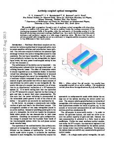
ble to fabricate high-index-contrast nano-waveguides which provide strong spatial confinement of the guided modes thus enhancing the nonlinear interactions. By using such waveguides one can achieve PM of quadratic nonlinear processes through dispersion engineering of guided modes [31, 56, 93–96]. This is a flexible approach that avoids the need for additional periodic poling of the waveguide and has been widely used for PM of four-wave mixing nonlinear interactions [97]. In this Section, it is shown that ultra-thin LiNbO3 waveguides suspended in air can be used for efficient cascaded THG. Air suspended LiNbO3 slab waveguides were shown to be feasible for fabrication at various thicknesses [60, 98] and with higher quality in comparison to epitaxially grown LiNbO3 films [99]. The SHG in LiNbO3 material was studied theoretically in photonic crystals [96] and thin films on a substrate [93]. Furthermore efficient SHG was also predicted for AlGaAs slot waveguides [31], rods [94] and thin high-index-contrast AlGaAs/oxidized AlAs waveguides [95]. However the simultaneous PM of cascaded parametric processes in nano-waveguides has never been considered. It is demonstrated that complete PM of both cascaded quadratic processes can be realized simultaneously in a single waveguide without periodic poling. The high quadratic nonlinearity of LiNbO3 and tight field confinement in a nano-waveguide can allow strong enhancement of the conversion efficiency in comparison to quasi-phase-matched cascaded THG in periodically poled LiNbO3 waveguides [41, 92] and direct THG through cubic nonlinearity in silica glass waveguides [100]. To get a better insight in the possibilities for PM of the cascaded THG, I first develop a semi-analytical model that describes PM in LiNbO3 slab waveguides. I then show that this model can also be used as a starting point to design more practical nanowire waveguides. For efficient frequency conversion, in addition to PM, it is desirable to employ nonlinear interactions based on the largest nonlinear susceptibility tensor components. I therefore perform a systematic analysis of different slab orientations, and find that the most efficient cascaded THG is realized in a z-cut LiNbO3 slab waveguide with all interacting waves propagating in y direction, as illustrated in Fig. 2.1(a). I determine that the optimal THG process in the LiNbO3 slab waveguide is the conversion of pump TE0 mode into SH TM0 mode, and then their mixing to the TH TE1 mode in the process of sum-frequency generation [see Fig. 2.1(b)]. The electric field profiles of the guided modes can be expressed as E = exp[−iωt + ik0 neff (ω)y] × [Ex (z, ω), Ey (z, ω), Ez (z, ω)]. Here neff is the effective mode index, ω is the fundamental optical frequency, k0 = ω/c, and c is the speed of light in vacuum. For TE modes, the electric field is polarized in the x direction (Ez = Ey = 0), and the electric field component Ex satisfies the wave equation: ∂ 2 Ex /∂z 2 = 2 2 Ex k02 [(nTE eff ) − nx ], where nx,y,z are refractive index components, equal to those of
2.1 Second and third harmonic generation in nano-membranes
21
Figure 2.1: (a) LiNbO3 slab waveguide orientation for third-harmonic generation. (b) Electric field profiles for slab waveguide thickness of 200 nm and pump wavelength of 1542 nm. (c) Effective refractive index vs. slab waveguide thickness for pump, SH, and TH modes. (d) Normalized square of THG nonlinear coefficient for slab waveguide.
congruent LiNbO3 [101] for |z| ≤ h/2 (inside the slab waveguide), and nx,y,z = 1 for |z| > h/2 (outside the slab waveguide), where h is the waveguide thickness. For TM modes, the electric field is polarized in the y − z plane, and can be expressed −2 through the single component of the magnetic field Hx , Ez = −Z0 nTM eff nz Hx and 1/2 Ey = −iZ0 k0−1 n−2 . The wave y ∂Hx /∂z with the vacuum impedance Z0 = (µ0 /�0 ) 2 −2 2 TM 2 equation for the magnetic field is: nz ∂[ny ∂Hx /∂z]/∂z = Hz k0 [(neff ) − n2z ]. I solve the wave equations using the transfer matrix method [102] and obtain the effective indices and profiles of the guided modes. Then, the frequency conversion can be modeled by coupled equations for the amplitudes of narrowband pump, SH and TH modes [41], Ap , ASH and AT H respectively. In the case of undepleted pump approximation, Ap � ASH � AT H , the coupled equations for SHG discussed in the Section 1.1.2 and the corresponding equations for sum-frequency generation reduce to the following form: ∂ASH ∂y ∂AT H ∂y
= γSHG A2p exp (i∆kSHG y) ,
(2.1)
= γSFG ASH Ap exp (i∆kSFG y) .
(2.2)
Here ∆kSHG = 2(np − nSH )k0 , ∆kSFG = (3nTH − 2nSH − np )k0 are the wavenumber
22
Frequency conversion in nano-waveguides
TE1 TE1 TM is the effective mismatches, np = nTE eff (ω), nSH = neff (2ω), nTH = neff (3ω), neff index of TE1 mode. Employing the approach developed for SHG in nanostructured waveguides [96], I derive an expression for the nonlinear coefficients for SHG and SFG:
γSHG = ωd31 γSFG =
v u u t
v u u ωd16 t
2n2g,p ng,SH , n4p n2SH �0 c3 ASHG
(2.3)
18ng,p ng,SH ng,TH , n2p n2SH n2TH �0 c3 ASFG
(2.4)
TE1 TM where ng,p = ∂[ωnTE eff (ω)]/∂ω, ng,SH = ∂[ωneff (2ω)]/∂ω, ng,TH = ∂[ωneff (3ω)]/∂ω are the group indices which define the group velocity Vg = c/ng , d31 and d16 are the nonlinear optical coefficients of LiNbO3 . The normalized effective areas for SHG and SFG are:
�R
ASHG =
|
R NL
R
ASFG = R
dxdzEp2
�2 R
2 dxdzESH
dxdzEz∗ (x, z, 2ω)Ex2 (x, z, ω)|2
,
2 2 dxdzEp2 dxdzESH dxdzETH
R
(2.5)
R
2 , NL dxdzETH Ex∗ (x, z, ω)Ey∗ (x, z, 2ω)
(2.6)
where Ep = Ex (x, z, ω), ESH = [Ez2 (x, z, 2ω)+Ey2 (x, z, 2ω)]1/2 , ETH = ExTE1 (x, z, 3ω) are pump, SH and TH electric field absolute values, NL is a waveguide cross-section area, and ∗ stands for complex conjugation. For slab waveguides, the result of the integration over x will depend on the input beam width and profile. The highest THG efficiency is realized when SHG and SFG processes are phasematched simultaneously. In Fig. 2.1(c) it is shown that the effective refractive indices for all three harmonics with pump wavelength λp = 1542 nm are matched for a slab waveguide thickness of h = 206 nm. In this case the normalized conversion efficiencies for SHG and SFG in the undepleted narrowband pump approximation 2 2 can be defined as ηSHG = γSHG and ηSFG = γSFG . I estimate these efficiencies for the beam width equal to 1.77 µm in x direction (for the later comparison with fully vectorial calculation for nanowire waveguides): ηSHG = 347 %W−1 cm−2 , ηSFG = 215 %W−1 cm−2 . Total normalized conversion efficiency for phase-matched THG in 2 a waveguide length L can be defined as ηTHG = γTHG = ηSHG ηSFG |Ap |2 L2 /4. It is most remarkable that the slab waveguide thickness of h = 206 nm also corresponds to the strongest mode confinement and therefore to the highest nonlinear coefficient for THG, as shown in Fig. 2.1(d). I find that both PM conditions can be satisfied for different pump wavelengths
2.1 Second and third harmonic generation in nano-membranes
23
Figure 2.2:
The slab waveguide thickness (solid line, left axis) and temperature (dashed line, right axis) corresponding to exact PM for THG vs. pump wavelength.
by manufacturing a slab waveguide with appropriate thickness and by heating or cooling the sample, see Fig. 2.2. Let us now consider a nanowire waveguide with rectangular cross-section [see Fig. 2.3(a)], in which higher conversion efficiency can be achieved due to mode confinement in both transverse dimensions (z, x). I calculate numerically the pump, SH and TH modes in nano-waveguides with a rectangular cross-section using the COMSOL RF module. I start with crystal orientation and waveguide thickness h as in the slab waveguide analysis and then optimize the pump frequency and waveguide thickness to achieve complete PM. Characteristic modes of the interacting pump, SH and TH waves in the waveguide are shown in Figs. 2.3(b-d). As we can see in Figs. 2.3(e,f) that by varying the waveguide width b, one can satisfy the conditions for fully phase-matched THG for pump wavelengths between 1.35 µm and 1.55 µm. Using the calculated mode profiles I obtain the effective areas and the conversion efficiency for the cascaded THG. For λp = 1471 nm, a waveguide of width b = 1.77 µm and thickness h = 181 nm, the effective areas are ASHG = 22 µm2 and ASFG = 26 µm2 . This corresponds to normalized conversion efficiencies ηSHG = 261 %W−1 cm−2 , ηSFG = 279 %W−1 cm−2 . These values agree well with my previous estimates based on semi-analytical analysis for a slab waveguide. Total THG conversion efficiency ηTHG is sufficiently high to predict, in an ideal waveguide with a 3 mm interaction length, the generation of 1 mW green light from 33 mW telecommunications radiation. To compare with the best result reported to date, such TH output from ideal periodically-poled LiNbO3 structure is predicted to require 10 times longer crystal and almost 4 times higher pump power [92]. The realization of LiNbO3 nano-waveguides with the desired geometry is feasible by means of ion-beam enhanced etching (IBEE). The IBEE technology has been shown to be ideally suited for the fabrication of complex photonic crystal structures [103, 104] and can also be applied to fabricate the proposed nano-waveguides. In this process the geometry of a patterned masking layer is transferred into the crystal by a series of high energy ion irradiation. The irradiated and thus damaged regions are subsequently removed by chemical wet etching, resulting in an
24
Frequency conversion in nano-waveguides
Figure 2.3: (a) Scheme of the air-suspended LiNbO3 waveguide. (b,c,d) Intensity profiles of phase-matched (b) pump, (c) SH, (d) TH waves for a waveguide width b = 1.77 µm and thickness h = 181 nm. (e) The pump wavelength λp and (f) the waveguide thickness h corresponding to exact PM for THG vs. waveguide width b.
air-bridged structure, as shown schematically in Fig. 2.3(a). The complete PM requires high manufacturing precision. The thickness of 100 µm long slab waveguides has to be controlled with nanometer accuracy, which may be challenging with technologies currently available. Nevertheless, THG may be realized even when the individual SHG and SFG processes are slightly mismatched, provided that a single PM condition between the pump and TH waves is satisfied [41]. I anticipate that broadband THG may be possible in the latter case, although at the trade-off of lower conversion efficiency. In conclusion, in this Section it was shown that the modal dispersion in airsuspended lithium niobate waveguides can be used to simultaneously phase-match two independent nonlinear parametric processes, resulting in cascaded third harmonic generation. I anticipate that these findings may stimulate the realization of new families of efficient frequency mixers and converters to the third harmonic, for applications in compact light sources and laser display technologies. In the next Section we will see how careful dispersion engineering in nanowaveguides can be employed for four-wave-mixing of short pulses.
2.2 Pulsed four-wave-mixing in nano-tapers
25
2.2 Pulsed four-wave-mixing in nano-tapers In the Section 2.1 we looked at new opportunities provided by nano-waveguiding for cascaded quadratic nonlinear processes. In this Section I demonstrate a novel application of dispersion engineering for cubic nonlinear frequency conversion introduced in the Section 1.1.5. I suggest an application of pump-degenerate four-wave mixing process in tapered waveguides for generation of ultrashort pulses with central frequency tunable over the material transparency range. This method can produce strongly compressed frequency-converted pulses in presence of group velocity mismatch and group velocity dispersion. Additionally, the proposed technique does not require pulse phase synchronization and effectively operates for strongly chirped pump pulses, thus enabling the use of longer nonlinear media for high conversion efficiency. As discussed in the Section 1.2.1, dispersion engineered waveguiding opens a range of new opportunities. Recently developed silicon-on-insulator (SOI) subwavelength waveguides combine enhanced cubic nonlinearity and possibility of onchip integration, allowing for effective and relatively broadband frequency conversion via four-wave mixing [105, 106]. Whereas such waveguides could facilitate fairly broadband frequency conversion, one of the main limiting factors in case of significantly different pump and idler frequencies is the group-velocity mismatch. In combination with group-velocity dispersion, it may lead to temporal broadening of frequency-converted pulses and reduced conversion efficiency [107]. One common approach to mitigate this effect is to use short nonlinear samples. However then for good conversion efficiency high peak power pump is required, which can lead to undesirable nonlinear pulse distortion. Interestingly, FWM dynamics in media with cubic nonlinearity can have certain similarities to second harmonic generation in quadratic nonlinear media [108]. The pulse compression in the process of SHG can be realized in bulk [109–111] and aperiodically poled nonlinear crystals [112, 113]. The latter technique was also applied to optical parametric amplification (OPA) with continuous-wave (CW) seeding, but only in degenerate regime [114]. The main remaining limitation for these methods is that the generation of compressed pulses through SHG at arbitrary reconfigurable wavelengths is not possible. Whereas GVM-induced pulse broadening can also be alleviated for sum-frequency [115, 116] and difference-frequency generation [117], which may allow more tunability over the converted pulse wavelength, the required precise synchronization of two pump pulses may be complicated to implement. In this Section, I propose a method for generating ultrashort pulses using the process of pump-degenerate four-wave mixing in sub-wavelength tapered waveguides with enhanced cubic nonlinearity. The idler wavelength can be tuned arbitrarily
26
Frequency conversion in nano-waveguides
within very broad range by adjusting the frequency detuning of monochromatic signal wave with respect to the pump and choosing the appropriate waveguide tapering. I demonstrate that highly efficient idler pulse compression can be achieved in sub-wavelength tapered waveguides using chirped pump pulses, despite large GVM. I show that the process of idler pulse generation is mathematically analogous to second-harmonic generation for weak pump, and that the pulse compression is increased even further in the regime of high conversion efficiency. Another advantage of the proposed scheme is that it does not require either pumping with synchronized pulses or the phase synchronization between input pump and signal waves. I study the dynamics of collinear lossless four-wave mixing process with degenerate pump [see phase-matching diagram in Fig. 2.4] and use coupled-wave equations based on equations for four-wave-mixing from the Section 1.1.5 and equations for pulse propagation from the Section 1.2.1 in low pump depletion approximation [106]: ∂As iDs (z) ∂ 2 As ∂As + δsp (z) + = ∂z ∂τ 2 ∂τ 2 − iγs (z)A2p A∗i exp[iξ(z)] − 2iγs (z)|Ap |2 As ,
(2.7)
∂Ai ∂Ai iDi (z) ∂ Ai + δip (z) + = ∂z ∂τ 2 ∂τ 2 − iγi (z)A2p A∗s exp[iξ(z)] − 2iγi (z)|Ap |2 Ai ,
(2.8)
2
ωn2 ∂Ap iDp (z) ∂ 2 Ap + = −i |Ap |2 Ap . ∂z 2 ∂τ 2 c
(2.9)
Here z is the propagation distance, τ is the time relative to the pump pulse center. The subscripts s, i and p denote the variables corresponding to the signal, idler, and pump waves, respectively, As,i,p are the complex slowly varying field envelopes, normalized such that Ps,i,p = |As,i,p |2 represent the optical powers. The coefficients δ define the group velocity mismatches between the signal (δsp ) or idler (δip ) waves and the pump, while coefficients D define the group velocity dispersion for the signal (Ds ), idler (Di ) and pump (Dp ) waves. The γs,i,p are effective nonlinear coefficients where subscript s and i correspond to FWM for signal and idler and p to pump self-phase-modulation processes. The function ξ(z) = 2πz[2np (z)/λp − ns (z)/λs − ni (z)/λi ] defines the phase velocity mismatch between the interacting waves, where λs,i,p are the central wavelengths. I now formulate the optimal conditions for the generation of ultrashort idler pulses. In order to reduce the pump self-action and nonlinear absorption, it is beneficial to lower the peak pump power while preserving the high total pulse energy. This requirement is satisfied for chirped pulses. Specifically, I consider a chirped
27
2.2 Pulsed four-wave-mixing in nano-tapers
gaussian pump pulse with the input profile: "
Ap (0, τ ) =
Pp1/2
#
−τ 2 exp , (2τ02 + 2iξp2 )
(2.10)
where Pp is the peak input power, ξp is a pulse chirp coefficient, and τ0 corresponds to the width of non-chirped pump pulse. As the signal input, I take small-amplitude continuous-wave field (or a long narrow-band pulse) and consider zero idler amplitude at the input, see Fig. 2.4. In this approach, the idler pulse wavelength can be −1 −1 tuned by choosing the pump and signal wavelengths, as λ−1 i = 2λp − λs . Whereas similar conversion scheme was previously developed for optical gating in homogeneous waveguides [108], I demonstrate below that idler pulse can be compressed in a waveguide with specially designed tapering such that the phase-matching condition varies along the waveguide as follows: �
ξ(z) = ξw z −
L 2
�2
.
(2.11)
Here L is the total waveguide length and ξw is the effective tapering coefficient, which value should be optimized to achieve maximum pulse compression. I first derive an analytical expression for the optimal value ξw under certain simplifications. It assumed that GVM and nonlinearity are practically constant along the waveguide, δs,i,p (z) = δs,i,p and γs,i,p (z) = γs,i,p , and neglect GVD, Ds,i,p ≈ 0. I also consider the regime of low conversion, when the pump power is rather small such that Ap � As � Ai along the waveguide. Then, the nonlinear terms in Eq. (2.7) and Eq. (2.9) can be neglected, and there is almost no temporal reshaping of input pump pulse and CW signal. Finally, Eq. (2.8) can be reduced to the following expression: ∂Ai ∂Ai + δip = −iγA2p A∗s exp [iξ(z)]. ∂z ∂τ
(2.12)
Since under these assumptions As remains a CW signal, this equation has the same form as for the second-harmonic wave in the SHG process in the non-depleted pump approximation where ξ(z) can be engineered through crystal poling [113]. I then adopt the results for pulse compression with SHG [113] and determine the optimal pump chirp as ξp = δip ξw−1/2 . (2.13) I have checked by direct numerical modeling of Eqs. (2.7)–(2.9) that this approach can be applied to a range of different platforms and wavelengths. As an example, the plausibility of experimental implementation with SOI platform for
28
Frequency conversion in nano-waveguides
Figure 2.4: Scheme of four-wave mixing with degenerate pulsed pump and CW signal inputs.
λs = 3.6 µm, λi = 2.16 µm, λp = 2.7 µm is demonstrated below. In mid-IR wavelength range the model assumptions of no two-photon absorption and no free-carrier generation are valid for both sub-ns and ps pulses [118]. I consider a rectangular cross-section Si waveguide on a SiO2 substrate with length L = 3 cm, height h = 1.2 µm and width linearly tapered from w = 740 nm at the input facet to w = 760 nm at the output facet. I study the waveguiding dispersion properties using COMSOL RF module and find that the phase mismatch for the pump-degenerate FWM ξ(z) incorporating TM signal and pump modes and TE idler mode is equal to zero in the center of the waveguide, i.e. ξ(L/2) = 0. I confirm that the dependance of the phase mismatch ξ(z) matches very closely the optimal dependence in Eq. (2.11) with tapering coefficient ξw ≈ −0.26 mm−2 . The other dispersion parameters exhibit small linear changes with z: δsp (z) = 2.48 − 0.16z/L [ns/m], δip (z) = −1.39 + 0.14z/L [ns/m], Ds (z) = −24.5 + 1.1z/L [ps2 /m], Di (z) = −0.95 + 0.02z/L [ps2 /m], Dp (z) = −7.45 + 0.5z/L [ps2 /m]. Since cubic nonlinearity for wave mixing involving different frequencies is not yet characterized for Si in midIR region, I make an order-of-magnitude estimate for the nonlinear coefficients as γs,i,p ' 2πn2 /[λs,i,p a(eff) ], with material nonlinearity n2 = 6 · 10−5 cm2 /GW [106] and the effective area a(eff) ≈ 0.75 µm2 . I check that the changes of γs,i,p within one order of magnitude do not qualitatively affect the results. For considered tapering the effective area for all modes changes with z by less than 2%, and therefore I neglect this change. I consider an input chirped gaussian pump pulse with Pp = 100 mW, τ0 = 1 ps, and the chirp according to Eq. (2.13) as ξp = δip (L/2)/ξw1/2 = 2.58 ps. The overall length of the pump pulse is then [(2−1/2 τ0 )2 + (21/2 ξp2 /τ0 )2 ]1/2 = 9.44 ps. The initial power of CW signal is Ps = 1 mW, and there is no idler input. Unlike degenerate OPA [114], the phase synchronization between pump and signal waves is not required for pump-degenerate FWM, as it is automatically compensated by the idler phase. Now I demonstrate the results of numerical simulation with Eqs. (2.7)-(2.9) and parameters for SOI waveguide provided above. The dynamics of normalized idler pulse, spectrum and peak power along the propagation are shown in Figs. 2.5(ac). We see that at the initial propagation stage up to z ≈ 1 cm [Fig. 2.5(a)], the
2.2 Pulsed four-wave-mixing in nano-tapers
29
Figure 2.5: (a,d) Dependence of the normalized idler temporal intensity profiles on the propagation distance. (b,e) Corresponding evolution of the normalized idler spectra. (c,f) Dependence of the idler-pulse peak power on the propagation distance. The waveguide width is (a,b,c) linearly tapered w(z) = 740+20z/L [nm] or (d,e,f) not tapered with constant width w = 750 nm.
idler pulse goes through unstable transition where the effects of non-phase-matched generation from the center of the pump pulse and phase-matched generation from the low-intensity pump pulse lobe compete. It happens because in chirped pump pulse the wavelengths are distributed along its duration, and only those at the beginning of the pulse are phase-matched in the initial section of the tapered waveguide. At z ≈ 1 cm the idler wave is now generated effectively at phase-matched wavelength, and thus idler pulse compression begins and continues throughout the taper. During this process different idler frequency components are generated along the waveguide [Fig. 2.5(b)] and are effectively assembled together by GVM in temporal domain [Fig. 2.5(a)]. The idler peak power grows [Fig. 2.5(c)] until the idler spectrum width becomes similar to that of the pump, and idler pulse is compressed to τ0 = 1 ps. At that point the idler power reaches 0.4 µW, the signal power is increased to 4.9 mW, and the pump power stays unchanged, which means that the relation Ap � As � Ai , which was used to derive Eq. (2.13), remains satisfied. I now compare these results with non-tapered waveguide of constant width w = 750 nm corresponding to the exact phase-matching of the central wavelengths, see Figs. 2.5(d-f). We see in Fig. 2.5(d) that initially there is some degree of pulse compression in analogy with pulse conversion in quadratic media [110, 115, 116]. However at z ≈ 5 mm the pulse begins to spread, while its spectrum is narrowed [Fig. 2.5(e)] and its peak power no longer grows [Fig. 2.5(f)]. Even if the length L is equal to the optimal value z = 5 mm, the non-tapered waveguide still provides four
30
Frequency conversion in nano-waveguides
times less pulse compression and four times less conversion efficiency compared to the tapered structure. Finally I demonstrate generation of compressed idler pulse in the tapered waveguide with higher conversion efficiency. As I increase the pump peak power from Pp = 100 mW to Pp = 5 W, the nonlinear interaction starts to change both the signal and idler profiles, and the condition As � Ai no longer applies. Simulations show that in this regime, the idler peak power grows much faster than the signal power and reaches 15 mW, while the signal power is increased only to 7 mW. As a result the idler pulse compression occurs faster, spectrum becomes broader, and the compression ratio is enhanced by 10% in comparison to the low pump power case. In the provided examples the GVD played relatively minor role. However both the linear tapering and GVD lead to linear chirp (or compensation of linear chirp) in frequency-converted pulse. Therefore they can compensate each other even in the case of very large GVD. Mitigation of higher orders of dispersion, as well as studying highly tapered waveguides with stronger dependance of GVM and GVD on propagation distance may be of interest for the future research. In conclusion, in this Section a method for efficient frequency conversion combined with pulse compression based on nonlinear four-wave mixing process with pre-chirped pump pulses is suggested. This approach can be realized in tapered sub-wavelength waveguides. I expect that the proposed method will find applications for efficient short pulse frequency conversion useful for signal processing in telecommunications and for production of affordable infrared lasers with arbitrary wavelengths. This Chapter showcases novel efficient frequency conversion regimes that can be achieved in sub-wavelength nonlinear waveguides. In the next Chapter we will have a look at frequency conversion and pulse control in more complex structures containing larger conventional nonlinear waveguides.
Chapter 3
Pulse dynamics induced by cascaded second harmonic generation
3.1 Efficient all-optical switching in quadratic nonlinear directional couplers In the previous Chapter we saw how control over the dispersion in nanowaveguides allowed for efficient frequency conversion in cw and pulsed regimes. In this Chapter I will demonstrate a different approach to dispersion control and pulse shaping through waveguide coupling and cascaded quadratic nonlinearity. This Chapter includes the results of temporal and spectral experimental characterization of pulses propagating in micro-scale couplers and waveguide arrays. Pulse dynamics in this Chapter is defined by the cascaded interaction between pump and SH waves described in the Section 1.1.4 and by an interaction between waves in coupled waveguides introduced in the Section 1.2.2. In this Section† I demonstrate the results of the experimental characterization of temporal dynamics during all-optical switching in nonlinear directional couplers in periodically poled lithium niobate. The characteristic features of such switching, including asymmetric pulse break-up and back-switching have been fully experimentally characterized in quantitative agreement with the theoretical predictions. Based on the time-resolved measurement of intensity-dependent switching the theoretically long-known continuous-wave switching curve has experimentally been confirmed. All-optical switching in nonlinear directional couplers (NLDCs) is one of the most fundamental processes involving intensity-dependent light propagation. Importantly, the intensity-dependent mode coupling in the NLDC forms the basis for an understanding of wave propagation in other more complex nonlinear systems like waveguide arrays and solitons in slab waveguides. During the wave propagation †
In this Section my experimental results are compared with simulations provided by Prof. Roland Schiek from the University of Regensburg.
32
Pulse dynamics induced by cascaded second harmonic generation
in NLDC the modes of a system are changed by the nonlinearity. The resulting modification of the coupling between the modes and their superposition determines the intensity pattern at the output of the system dependent on the input power. For ultrafast all-optical switching typically short pulses and fast nonlinear processes such as Kerr-like or cascaded quadratic nonlinearities are employed. The quadratic NLDC is by far superior in terms of power requirements and flexibility, however, due to the involvement of more than one optical frequency and a strong frequency dependence of the nonlinearity the system becomes more complex. Theoretically the NLDC has been described a long time ago [65] and NLDCs based on cubic Kerr-type nonlinearities have intensively been studied in the laboratories [119, 120]. Following these works, quadratic NLDCs were also studied theoretically [121] and experimentally [68, 122], revealing their greater flexibility due to a tunability of the cascaded quadratic nonlinearity. Similar to the cubic case it was shown that complete switching is in general prevented by pulse break-up for most of the experimentally available pulses [121, 123]. While there have been a number of experiments aiming to directly observe the temporal dynamics of short pulses in cubic all-optical switches [124], a measurement of the pulse shaping in a quadratic NLDC was lacking. Due to the complexity of the pulse dynamics, determined by the frequency dependence of nonlinearity and group velocity, it is interesting to directly measure the performance of such quadratic NLDCs and to compare it with the existing theoretical studies [121]. In this Section I present the results of high-resolution measurements of the output pulses emerging from quadratic nonlinear couplers with frequency-resolved optical gating technology (FROG) demonstrating the such details of temporal switching as incomplete switching in the pulse wings, back-switching in the center of the pulse, and asymmetry of the resulting pulse break-up. Both single channel waveguides and pairs of linearly coupled waveguides were fabricated by indiffusion of 7-µm-wide and 100-nm-thick titanium stripes at 1060◦ C for 8.5 hours in a L = 50-mm-long Z-cut congruent lithium niobate (LiNbO3 ) crystal with propagation along the crystallographic X axis. To achieve large intensitydependent phase shifts for the fundamental wave due to the cascaded quadratic nonlinearity, type I wavelength- and temperature-tunable second-harmonic generation was implemented. The phase-matching was provided by quasi-phase-matching introduced in the Section 1.1.2. An electric-field-poled QPM grating with a period of ΛQPM = 16.751 µm yielded phase-matching for SHG between the TM00 modes for a FW wavelength of λPM = 1522 nm at room temperature. The end facets were polished for end-fire coupling and were anti-reflection coated, having reflectivities of ≈ 1% for the FW and 14 % for the second harmonic. Linear losses between 0.2 and 0.23 dB/cm for the FW and 0.65 and 0.75 dB/cm for the SH have been mea-
3.1 Efficient all-optical switching in quadratic nonlinear directional couplers 33 sured. To prevent a photorefractive (PR) detuning of the SHG resonance and to minimize a PR shift of the coupling length the sample was heated to 170-240◦ C which increased λPM to standard telecommunications wavelength of 1550 nm. The numerical simulations of the switching dynamics were performed by Prof. Roland Schiek from the University of Regensburg and were based on a coupled-mode theory in the frequency domain [121] using the measured input pulse envelope and phase. The parameters for the model were all measured with high precision, and the modeling yields excellent quantitative agreement with the measurements without any fitting parameters. At a wavelength of 1550 nm a coupler with a center-to-center waveguide separation of 18.3 µm with a coupling length of Lc = 54 mm is the closest to a half-beat-length coupler in the sample. The SH modes of both arms are not coupled due to the strong confinement of these modes. The propagation constants for fundamental wave βFW and second harmonic βSH were calculated with a mode RR 2 ∗ solver. The overlap integral K (2) = dxdy EFW (x, y) ESH (x, y) = 8.3·108 V3 /m for SHG was determined from mode-shape measurements. Here, EFW/SH (x, y) are the transverse electric fields of the waveguide modes normalized to 1 W. The quadratic nonlinear susceptibility in this system was measured to be d33 = 20.6 pm/V [125]. The experimental setup is shown in Fig. 3.1. Pulses from an amplified modelocked Pritel fiber laser with a repetition rate of 5 MHz, at a wavelength of λFW = 1550.88 nm, bandwidth of 0.35 nm and a pulse length of 9 ps at full width at half maximum (FWHM) were end-fire coupled into the waveguides. The asymmetric SHG tuning curve from a single waveguide in Fig. 3.2(a) indicates a nonuniform distribution of the wave-vector mismatch due to a temperature gradient in the heated crystal [126]. The SH output is minimized for a positive wave-vector mismatch ∆k = 2βFW − βSH + 2π/Λ below the phase-matching temperature TPM = 219◦ C. The temperature dependence of the normalized wave-vector mismatch is given by ∆kL = 1.8π × (219 − T /◦ C). The total throughput of 80% is reduced close to phase-matching when the FW is depleted and part of the energy propagates in the more lossy SH mode. I investigated all-optical switching in the NLDC by coupling the light into one arm of a half-beat-length coupler and observing the output dependent on the input power [see Fig. 3.1]. The FW and SH outputs from both coupler arms were separated spatially and imaged onto InGaAs and CCD cameras. The FW and SH average power from both arms was measured with four photodiodes. By using the measured input pulse shape and the pulse repetition rate, the average FW power is converted to the peak power Pin and to the pulse energy U . Fig. 3.2(b) shows a typical measured switching curve showing the output pulse energy Uout from the cross and the bar arm normalized to the input pulse energy Uin . The switching power Psa is the input peak power for equal average output from both arms. Due to a small
34
Pulse dynamics induced by cascaded second harmonic generation
Cooled IR (or visible) CCD camera for alignment
photo-detector
adjustable filter Laser + amplifier
temperature controlled oven with sample
SH&TH filters
1550nm
polariser
objectives
diaphragm
adjustable filter OSA
FROG
fibre coupling
photodetector
Figure 3.1: Scheme of the experimental setup for spectral-temporal characterization and switching measurements.
asymmetry of both coupler branches Psa is not equal for the left- (dashed line) and the right-arm (solid line) input. Furthermore, a small SH-induced photo-refraction index change slightly increases this asymmetry for larger powers. In theory (dotted curves in Fig. 3.2) the asymmetry which explains the deviations between calculated and measured data is neglected. Operating at temperatures below phase-matching the generated SH power is small [see Fig. 3.2(a)] and the switching does not suffer from FW depletion. The total throughput in Fig. 3.2(b) is therefore relatively constant. Only for larger input powers when most of the FW and the generated SH stay in the bar arm, larger SH losses yield an observable reduced total throughput. I characterized the power-dependent switching at different temperatures and in different couplers. The dependence of Psa on the phase-mismatch and on the coupling length agrees well with the theory for all measurements. Importantly, the couplers also switch at higher temperatures with negative phase shifts, but because of stronger SHG the switching curves are not as clean as with the positive phase shifts. For the characterization of the temporal dynamics I measured the FW output
3.1 Efficient all-optical switching in quadratic nonlinear directional couplers 35
Figure 3.2: (a) Temperature-tuned SHG and FW-depletion from a single waveguide for an input peak power Pin = 1.6 W. (b) Normalized FW output pulse energy from the bar and the cross arm (see inset) versus Pin from a half-beat-length coupler for left- (dashed line) and right-arm (solid line) input; Lc = 54 mm, 210◦ C. The SH and the total throughput are also shown. Dotted lines represent numerical simulation results.
pulses of both arms separately with a FROG system from Southern Photonics. The spectra were monitored with an optical spectrum analyzer. Fig. 3.3 shows typical switching dynamics. At low input power Fig. 3.3(a) shows the beginning of switching in the pulse center where the power from the cross arm starts to switch to the bar arm. For larger Pin the strongly increased power in the pulse center in the bar arm coincides with a corresponding, depleted power in the cross arm. In the low-intensity parts of the pulse (pulse wings) the light couples in a linear fashion to the cross arm, while
36
Pulse dynamics induced by cascaded second harmonic generation
1.0
P
P
= 48 W
in
in
= 106 W
-10
0
10
20
-10
Time [ps]
0
10
20
Time [ps]
3
1.0
Cross
(c)
Bar
Bar P
in
(d)
= 160 W
2 Input
0.5 Input
1
Bar + Cross
0.0
-10
0
10
20
-10
Time [ps]
Cross
(e)
OSA P
0 20
10
Time [ps]
1.0
Spectrum
0
Phase [rad]
Power
Bar
Bar
0.5
0.0
Power
Cross
(b)
Cross
(a)
in
Bar
(f)
OSA
= 160 W
P
in
= 160 W
0.5
0.0
1550 Wavelength [nm]
1555
1550
1555
Wavelength [nm]
Figure 3.3: Normalized pulse traces from the output arms of a half-beat-length coupler; Lc = 54 mm. (a) Pin = 48 W < Psa , (b) Pin = 106 W ≈ 1.2 × Psa , (c) Pin = 160 W > Psa . (d) Input pulse compared to the total FW output; Pin = 160 W. The phases of the input pulse and the output pulse from the bar arm are also shown. (e) and (f) Measured and recovered spectra (from FROG traces) of the pulses from the cross and the bar arm in (c). The temperature was maintained at 205◦ C. Dotted lines demonstrate numerical simulation results.
the higher-intensity pulse center is switched to the bar arm. The resulting pulse break-up in the cross arm is observed in Figs. 3.3(b,c). For Pin slightly above Psa [Fig. 3.3(b)] the power in the pulse center equals the power for complete switching and therefore the center of the pulse remains in the bar arm. A further increase of Pin [Fig. 3.3(c)] shows a complete switching of the pulse intensity for two points on both sides of the pulse peak. In the pulse center back switching is now experimentally observed and agrees with previous theory [65].
3.1 Efficient all-optical switching in quadratic nonlinear directional couplers 37 The phase of the input pulse shows a slight up-chirp [Fig. 3.3(d)]. The positive nonlinear phase shift increases this chirp for an increasing power. The resulting larger chirp of the output pulse is shown for the bar arm pulse [Fig. 3.3(d), dashdotted line]. The time direction in the FROG retrieval was found from this increased up-chirp. Figs. 3.3(e,f) show as representative examples the quantitative agreement between retrieved and measured spectra with strong self-phase modulation. The sum of the temporal profiles of both output arms approximately equals the measured input pulse profile for all the measurements with less than 10% generated SH, as shown in Fig. 3.3(d). This shows that in the first approximation the quadratic cascaded nonlinearity acts quasi-instantaneously for an operation with low FW-depletion and 9-ps-long pulses. However, the observed asymmetry of the switching can not entirely be explained by the asymmetric laser pulse. Numerical simulations show that the wavelength dependence of the phase-mismatch yields different effective nonlinearities for the different spectral components which introduces a special kind of nonlinear dispersion. Together with the linear dispersion (SH walk-off) the pulse-form-induced asymmetry is magnified and the pulses broaden and develop a tail. Therefore, for the 9-ps-long pulses the “temporal non-locality” of the cascaded nonlinearity [127] influences the pulse propagation and – especially in the second half of the pulses – the assumption of an instantaneous nonlinearity can not exactly explain the details of the pulse dynamics. Another important consequence of the exact time-resolved measurement of the optical switching is the possibility to determine the continuous-wave switching curve. For a pure instantaneous nonlinearity in a dispersion-free system it is possible to retrieve the cw switching curve by plotting the instantaneous normalized powers from both output arms versus the instantaneous input power of the bell-shaped input pulse. Corresponding plots of the experimental data indeed show the behavior of switching. However, the deviations of the experimental system from the dispersionfree system with partly non-instantaneous nonlinearity are strong enough to disturb a determined cw switching characteristic in the second half of the pulse. Therefore, in order to measure a cw switching curve as precisely as possible, traces of switched pulses from both arms were measured while increasing the input power by small increments with the results illustrated in Fig. 3.4. After determining the ratio of the pulse energies from both channels from the measured switching curve in Fig. 3.4(c) the pulse traces were calibrated and normalized to the input. The color-coded contour plots in Figs. 3.4(a,b) show the calibrated and normalized pulse traces dependent on the input peak power Pin . After evaluating the powers in the pulse center, the switching curve for the momentary peak power shown in Fig. 3.4(d) was derived. The power scans are marked by white lines
38
Pulse dynamics induced by cascaded second harmonic generation
Figure 3.4: Normalized experimental pulse traces dependent on the input peak power Pin from (a) the cross and (b) the bar arm. A center-to-center waveguide separation of 18.7 µm corresponds to Lc = 68 mm; 210◦ C. (c) Measured and calculated switching curves for various pulse energies. (d) The experimental switching curve derived from (a,b) in the pulse center compared to a cw model and a numerical simulation.
in Figs. 3.4(a,b). The numerical simulation quantitatively agrees with the measured data. A scan from calculated contour plots [corresponding to Figs. 3.4(a,b)] provides a simulated switching curve for the momentary peak power in Fig. 3.4(d) (dotted lines) that quantitatively agrees with the measured curve. The remaining deviation from the switching curve calculated with a simple cw model [65, 121] is caused by the frequency dependence or temporal non-locality of the cascaded nonlinearity for the 9-ps-long pulses. The fringes in the FW power of the bar arm in the cw switching curve are caused by the generated SH in this arm [121]. To resolve these details and to decrease the deviation between the momentary-power switching curves from pulsed measurements and a cw switching curve the non-local regime of the cascaded nonlinearity needs to be suppressed and the nonlinearity needs to be faster. This could be done in experiments with longer pulse lengths or in experiments with larger phase-mismatch where the nonlinearity for all spectral components is more uniform. The measurement shows that the quadratic cascaded nonlinearity in LiNbO3 waveguides with a wave-vector mismatch larger than ∆kL > 16π can be considered
3.1 Efficient all-optical switching in quadratic nonlinear directional couplers 39 quasi-instantaneous down to the pulse lengths of ≈ 10 ps. In conclusion, in this Section I have for the first time experimentally demonstrated that quadratic nonlinear couplers experience pulse break-up, asymmetry and back switching. The obtained data agrees with extended numerical model and can be used to predictably engineer nonlinear optical waveguide systems based on the LiNbO3 platform and similar nonlinear crystals. In the next Section I will increase the complexity of the system by adding more coupled waveguides and experimentally investigate the process of light localization and pulse reshaping in quadratic nonlinear waveguide arrays.
40
Pulse dynamics induced by cascaded second harmonic generation
3.2 Spatiotemporal pulse shaping in quadratic nonlinear waveguide arrays In the previous Section I demonstrated the results of the first experimental characterization of pulse dynamics in quadratic nonlinear couplers, and in this Section† I will show what happens when this experiment is extended to waveguide arrays. The results include the details of spatiotemporal reshaping of laser pulses propagating in waveguide arrays with quadratic nonlinearity. These findings provide detailed understanding of pulse dynamics in quadratic nonlinear waveguide arrays and can be used to predictably engineer ultrafast all-optical circuits. Nonlinear waveguide arrays are considered important for all-optical signal routing in optical communications, since they allow ultrafast light-induced switching of short pules. Most of the works in this field concentrated on waveguide arrays with cubic nonlinearity [128–131], including the demonstration of discrete spatiotemporal X-waves [132, 133]. As it was mentioned in the previous Section, quadratic nonlinearity can allow alloptical switching at orders of magnitude lower powers [134], potentially leading to the realization of systems with higher energy efficiency. Recently the measurements of pulse spectra led to theoretical predictions of unusual temporal pulse dynamics in these systems [135]. In this Section I show the first experimental measurements of spatio-temporal reshaping of short pulses in waveguide arrays with quadratic noumenality. The system under investigation is described in Fig. 3.5. The sample used in the experiments reported here, shown schematically in Fig. 3.5(a), is manufactured by titanium indiffusion [136, 137]. It has a length of 71 mm and consists of 101 waveguides with a regular spacing of d = 15 µm. The numerically calculated intensity profiles of the modes investigated in this experiment are shown in Fig. 3.5(b). The modes at both the FW and SH frequencies are first order modes, namely the FW00 and SH00 modes. In principle the waveguides support higher order modes at the SH frequency [138], however in this experiment only FW00 and SH00 modes are excited due to established phase-matching conditions. Due to the evanescent overlap of the FW modes in waveguide with the refractive index modulation of the neighboring waveguide the propagation constants of the modes in the WGA form a continuous band of the longitudinal wavenumbers β FW in dependence on the transverse wavenumbers k ⊥ . In the case of weak diffraction this band is described by the †
In this Section the experimental results are obtained jointly by me and Dr. Frank Setzpfandt from the University of Jena and are compared with his simulations.
3.2 Spatiotemporal pulse shaping in quadratic nonlinear waveguide arrays 41
Figure 3.5: (a) Sketch of the waveguide array. (b) FW and SH modes taking part in the nonlinear interactions. (c) Scheme of the diffraction relations of FW and SH with the phase mismatch ∆β. The black arrows emerging from the FW band denote the bifurcation points of unstaggered (upwards) solitons for focusing nonlinearity and staggered (downwards) solitons for defocusing nonlinearity.
cosine diffraction relation introduced in the Section 1.2.2: �
�
β FW = β0FW + 2C FW cos k ⊥ ,
(3.1)
with the propagation constant of the FW00 mode in a single waveguide β0FW and the coupling constant C FW . For the investigated sample the coupling constant at a wavelength of 1560 nm is C FW = 80/ m. The resulting FW diffraction relation is shown in Fig. 3.5(c) with the blue line. The SH00 mode is much stronger localized than the FW00 mode as evidenced in Fig. 3.5(b). Hence, the linear coupling can be neglected [134] and the SH propagation constant in the WGA is always equal to the value of the propagation constant β0SH in a single waveguide. The ensuing flat diffraction relation is shown with the red line in Fig. 3.5(c). The nonlinear interaction between the FW and SH fields is strongly influenced
42
Pulse dynamics induced by cascaded second harmonic generation
by the phase mismatch ∆β, defined as ∆β = 2β0FW − β0SH +
2π , Λ
(3.2)
which is also indicated in Fig. 3.5(c). Here, Λ is the period of the periodically poled quasi-phasematching grating of the sample [139, 140], which periodically switches the orientation of the crystal axis and hence the sign of the nonlinear coefficient χ(2) along the propagation direction. In the experiments reported here, the period of the QPM grating is Λ = 16.805 µm, leading to phasematching between the FW00 and the SH00 mode at a wavelength of 1557.5 nm. At this wavelength the predominant nonlinear interaction is SHG. Due to the dispersive nature of the mode propagation constants, the phase mismatch can be changed by varying the FW and SH wavelengths. In this WGA, the phase mismatch becomes positive for FW wavelengths above the phasematching wavelength and negative for wavelengths below the phasematching wavelength. For non-zero phase mismatch SH is generated with a lower efficiency and, due to the different phase velocities of FW and SH, quickly converted back to FW. The subsequent generation and backconversion of SH is called cascading and leads to phase shifts of the FW [46, 126, 141–143]. These phase shifts induced by the cascading nonlinearity are comparable to phase induced by a Kerr nonlinearity but their sign and strength depend on the phase mismatch. For positive phase mismatch the ensuing effective cascading nonlinearity acting on the FW is focusing whereas it is defocusing for negative phase mismatch. Discrete spatial solitons can be excited for both scenarios [134, 144], in the first case they bifurcate from the top of the bands with a transverse wavenumber of k ⊥ = 0, in the second case they are generated from the bottom of the band at k ⊥ = ±π. Both situations are indicated by the arrows in Fig. 3.5. The temporal dynamics of these spatial solitons in the case of pulsed excitation is revealed in this Section of the thesis. The spatio-temporal intensity distribution of the FW part of the signal transmitted by the WGA is characterized with the modified setup introduced in the Section 3.1 sketched in Fig. 3.6(a). Pulsed light is generated by an erbium-doped fiber laser and amplifier system from Pritel with a repetition rate of 5 MHz. After coupling the light out of the laser fiber, the output power is monitored by splitting of a small fraction of the beam and measuring with an indium-gallium-arsenide (InGaAs) camera. To excite several waveguides of the WGA simultaneously, the input beam is shaped by a cylindric lens. Together with the coupling objective this forms a telescope for only the horizontal beam axis, leading to an elliptic input spot. With a cylindric lens of 300 mm focal length and a 10X F-L10B coupling objective of 12 mm focal length, the resulting input spot has a horizontal (vertical) full-width
pinhole
RG1000
10X MO
sample
10X MO
(a)
cyl. lens
3.2 Spatiotemporal pulse shaping in quadratic nonlinear waveguide arrays 43
InGaAs camera
fiber laser
FROG OSA (c) phase [rad]
intensity [a.u.]
(b)
time [ps]
time [ps]
Figure 3.6: (a) Scheme of the experiment showing the laser and beam shaping, the coupling to and from the sample with microscope objectives (MO) and the pulse analysis setup. (b) Intensity and (c) phase of the input pulses measured at 1553 nm (red) and 1561.8 nm (blue).
at half-maximum of 42 µm (4 µm). The output of the WGA is first filtered with an RG1000 filter to suppress the generated SH radiation. The FW is partly routed to a InGaAs camera which captures the spatial intensity distribution of the output of the WGA integrated over time. To measure the absolute output power the camera can be replaced by an InGaAs photodiode. The main FW output beam is spatially filtered by an iris which is placed in the image plane of the coupling objective. Here one waveguide is selected for further characterization. The light from the selected waveguide is then coupled to a single-mode fiber and routed either to an OSA or a FROG pulse measurement device [145]. The temporal profile of the pulse is numerically retrieved from the FROG trace, where the independently measured spectra are used for cross-checking the FROG traces and the results [146]. Amplitude and phase of the input pulses as measured separately with the FROG are shown in Fig. 3.6(b) and Fig. 3.6(c), respectively, for the two input wavelengths 1553 nm (red) and 1561.8 nm (blue). At the two wavelengths the input pulses are almost equal, showing a single intensity maximum and a negative chirp. To double-check the measurement results and to obtain information about the
Pulse dynamics induced by cascaded second harmonic generation
(b)
normalized power
(d)
(c)
normalized power
input peak power [W]
(a)
waveguide number -4
-3
time [ps]
44
-2
-1
0
1
2
3
4
1
2
3
4
time [ps]
(e)
normalized power
waveguide number
waveguide number
-4
-3
-2
-1
0
relative wavelength [nm]
Figure 3.7: Measurement result for focusing effective nonlinearity. (a) Power dependence of the spatial FW output of the WGA. (b) Comparison of the spatial outputs of measurement (blue line) and simulation (red circles) for an input peak power of 360 W. (c) Measured output spatio-spectral intensity distribution for the FW pulse with 360 W input peak power. (d,e) Comparison of the measured (blue) and simulated (red) (d) temporal and (e) spectral intensities in the waveguides given by the numbers in the plots. The intensity of the input pulse is alway plotted in light gray for comparison.
pulse dynamics in the sample I use numerical simulations based on the previous works [135, 138] provided by Dr. Frank Setzpfandt from the University of Jena. The dispersion in the WGA is determined by numerical calculations of the mode propagation constants for different wavelengths based on a precise description of the WGA index profile [147, 148] and measured values for the refractive index of lithium niobate [101]. Due to the long pulses used in this experiment and the resulting narrow spectrum the simulations reveal that the GVD is very small and has no effect on the experimental results. First the case of focusing nonlinearity is investigated. In this case the input wavelength λFW = 1561.8 nm is above the phasematching wavelength and the phase mismatch ∆β is positive. Results of measurements and simulations for this situation are summarized in Fig. 3.7. The FW spatial output intensity of the WGA in dependence on the input peak power is shown in Fig. 3.7(a). For low input peak powers the beam diffracts, forming a wide Gaussian output pattern. For increasing input power, the output beam is narrowing due to the stronger focusing nonlinearity, eventually forming a spatial discrete solitary wave at powers around 300 W [134].
3.2 Spatiotemporal pulse shaping in quadratic nonlinear waveguide arrays 45 For this power the measured spatial profile of the output beam is compared to the simulated spatial output profile in Fig. 3.7(b), showing the good correspondence between experimental and numerical results. The spatio-temporal structure of the output field is determined for an input peak power of 360 W by measuring FROG traces of a number of waveguides centered around the beam center. The input power for these measurements is larger than the minimum power for soliton generation to aid the power dependent measurement process and is the maximum power achievable with the used laser source. Additionally it enables us to get insight into the decay mechanism of the spatial solitary wave which is still excited as evidenced by the spatial profiles in Fig. 3.7(a). The optical intensity retrieved numerically from the measured FROG traces is shown in Fig. 3.7(c). Clearly close to the pulse center the fields are spatially more localized than in the wings. This leads to a temporal splitting of the pulses in the waveguides away from the beam center. The splitting is caused by the large power in the pulse center, which leads to strong spatial focusing whereas the pulse wings still diffract. The same phenomenon was described theoretically [149] and recently measured experimentally [150] in two-core couplers of the same waveguides as used in the WGAs here. This effect is also used in WGAs with Kerr-nonlinearity to excite X-shaped waves [132, 133, 151]. The measured and simulated temporal intensities are directly compared in Fig. 3.7(d). There is a good agreement between measurement (blue) and simulation (red). The small deviations can be attributed to small-scale inhomogeneities of the WGA which are not measurable.Additionally, the measured intensities are not very high, leading to operation of the FROG with long integration times and resulting in some noise in the measured FROG traces. This affects the FROG retrieval algorithm, thus fine details of the pulses may not be retrieved completely. As described above the pulse breakup in the waveguides apears far from the center of the excitation. The pulse lengths in the outer waveguides is notably larger than in the input pulse (light gray). This is explained by the fact that the two split pulses stem from the low power wings of the input pulse. The maximum intensity is localized in the leading sub-pulse, this characteristic is also found in the input pulse. In contrast to this, the maximum intensity of the pulses in the central waveguides is localized in the trailing edge of the pulses. This is due to the cascading character of the nonlinear effects. As has been shown earlier in film waveguides and waveguide arrays, the SH part of spatially trapped pulsed beams is trapped under the FW pulse [152–154]. Both pulses, FW and SH, are ideally traveling with a common group velocity, which is determined by the mutual phase shifts induced by cascading. Since the SH has a slower group velocity than the FW, this common group velocity is also somewhat smaller than the FW group velocity. Even temporal
46
Pulse dynamics induced by cascaded second harmonic generation
solitons in the presence of GVM are possible, if GVM and GVD are simultaneously balanced [155, 156]. For FW powers larger than necessary to maintain this balance, the SH pulse is slowly traveling to the rear of the FW pulse which is skewed towards its trailing edge [152, 154]. This movement of the SH pulse to the rear of the pulse will for longer propagation lengths lead to a emission of the SH from the pulse. This stops the cascading process and subsequently leads to broadening of the spatially localized wavepacket [135]. By choosing a slightly smaller peak power this process can be avoided and a more stable equilibrium of FW and SH pulses can be reached. Temporal solitons in the presence of GVM are not observable in this system due to very low GVD. Measured (red) and simulated (blue) spectra of the different waveguides for the case of positive mismatch and focusing nonlinearity are shown in Fig. 3.7(e). The plotted experimental spectra are measured with an OSA but agree well with spectra retrieved from the FROG. Again the spectrum of the input pulse (light gray) is presented for comparison. The measured and simulated output spectra are split into several peaks and are considerably broadened with respect to the input. The broadening is due to an effective self-phase modulation of the FW induced by cascading with the SH which increases the chirp of the pulse during propagation. From self-phase modulation in media with Kerr-nonlinearity also the spectral splitting is known [157]. The sharp central peak always occurs at the input wavelength of 1561.8 nm and is reproduced by the simulations only in the outer waveguides. Here it is a spectral signature of the low intensity pulse wings which do not undergo nonlinear effects. In the beam center the large spectral maxima at the input wavelength can only be attributed to low power excess light from the used laser source. The same measurements as for focusing nonlinearity are also conducted for defocusing nonlinearity at a wavelength of 1553 nm below the phasematching wavelength. To obtain spatial focusing, states at the edge of the Brillouin zone with transverse wavenumbers of k ⊥ = ±π are excited by tilting the exciting beam. Due to the lower coupling efficiency with tilted excitation, the highest peak power coupled to the WGA is 300 W instead of 360 W in the case of normal excitation discussed above. The power dependence of the WGA output intensity distribution is shown in Fig. 3.8(a). Again the spatial narrowing of the beam appears with increased input power. For the highest measured peak power a spatial soliton is formed, whose spatial structure agrees well with simulation results as shown in Fig. 3.8(b). The intensity maxima in the wings of the spatial distribution are now localized between the waveguides and stem from higher linear FW bands excited by the tilted input beam. Fig. 3.8(c) shows the measured spatio-temporal intensity distribution of the FW
3.2 Spatiotemporal pulse shaping in quadratic nonlinear waveguide arrays 47 (b)
normalized power
(d)
(c)
waveguide number -4
-3
time [ps]
normalized power
input peak power [W]
(a)
-2
-1
0
1
2
3
4
1
2
3
4
time [ps]
(e)
normalized power
waveguide number
waveguide number
-4
-3
-2
-1
0
relative wavelength [nm]
Figure 3.8: Measurement result for defocusing effective nonlinearity. (a) Power dependence of the spatial FW output of the WGA. (b) Comparison of the spatial outputs of measurement (blue line) and simulation (red circles) for an input peak power of 300 W. (c) Measured output spatio-spectral intensity distribution for the FW pulse with 300 W input peak power. (d,e) Comparison of the measured (blue) and simulated (red) (d) temporal and (e) spectral intensities in the waveguides given by the numbers in the plots. The intensity of the input pulse is always plotted in light gray for comparison.
output field at an input power of 300 W. Due to the lower input power the FROG measurements only produced meaningful results for the 7 inner waveguides. Similar to the focusing case the pulses in the outer waveguides are longer than in the center of the spatial intensity distribution. However, the splitting of the pulses is not as pronounced and can only be clearly observed in waveguides −2 and −3. The same observation is made when comparing measurement (blue) and simulation results (red) in each waveguide in Fig. 3.8 (d). The simulation shows a dip between the two sub-pulses in the outer waveguides which is not always resolved by the FROG. In comparison with the focusing case the measured output pulse shapes are much closer to the input pulse shape (light gray). This is attributed to the lower power and thus lower amount of generated SH and indicates a temporally more stable pulse. Hence, also the spatial localization could be maintained for a longer propagation distance. The measured and simulated spectra in Fig. 3.8(d) are distinctively different from the spectra obtained in the focusing case. They appear to be of the same width or narrower than the input spectrum. This can be explained by the chirp of the input
48
Pulse dynamics induced by cascaded second harmonic generation
power [W]
(a)
(c)
FWHM [waveguides]
power [W]
(b)
FW
input 35 mm 70 mm 105 mm
SH
time [ps] 360 W 330 W 300 W
propagation distance [mm]
Figure 3.9: (a) Simulated temporal intensity profiles of the FW pulse for focusing nonlinearity after different propagation lengths and (b) the corresponding SH pulse profiles. The input peak power is 360 W as in the results presented in Fig. 3.7. (c) Dependence of the width of the temporally integrated beam on the propagation distance for different input peak powers.
pulse. It has been shown in media with Kerr-nonlinearity, that adequately chirped pulses can undergo spectral narrowing if the nonlinear phase shift is compensating the chirp [158, 159]. The same effect takes place here, where the nonlinear phase shifts are generated by the effective cascading nonlinearity. The simulation shows that for an input peak power of 300 W the input chirp shown in Fig. 3.6(c) is almost exactly compensated by self-phase modulation. If the nonlinear phase shift is increased, e.g. by longer propagation or higher input power, the spectrum is broadened again since a chirp with different sign is now induced. The reasonably good agreement between measurement and theory allows to use simulation results to deduce the spatio-temporal intensities of the pulses also for parameters not accessible in the experiment. Here the simulations are used to investigate the decay process of spatially localized beams in WGAs. From the measurement and simulation results in Fig. 3.7(d) it can be reasoned that the GVM between FW and SH needs to be well balanced by the cascading nonlinearity to
3.2 Spatiotemporal pulse shaping in quadratic nonlinear waveguide arrays 49 avoid the escape of the SH part from under the FW pulse. The latter would severely hamper the cascading process and diffraction could no longer be inhibited. To further strengthen the reasoning for the GVM as cause of the spatial decay simulate the pulse propagation for the same parameters as in Fig. 3.7(d) but for longer propagation lengths. The simulated FW intensities in the central waveguide for different propagation lengths are shown in Fig. 3.9(a). The length of 70 mm (red) roughly corresponds to the sample length of 71 mm and hence represents the measured state. In the simulation result the gradual shift of the maximum of the FW pulse towards the trailing edge is clearly visible. The corresponding SH pulses are shown in Fig. 3.9(b). After a propagation length of 35 mm two SH contributions are visible. One is localized under the FW pulse and is subject to cascading. The trailing SH pulse is always generated upon excitation and radiates away freely without taking part in cascading interactions [160–162]. After 70 mm of propagation only the cascading part of the SH is in the plotted time domain, which clearly is locked to the FW pulse, however, as discussed before, is shifted towards the end of the FW pulse. Finally, after 100 mm of propagation a large portion of the SH is not longer retained under the FW pulse and radiates away. The radiation of the SH from under the FW pulse marks the break-up of the spatially localized beam as can be seen in the beam widths plotted in Fig. 3.9(c). Here the temporally integrated beam FWHM dependence on the propagation distance is shown for the input pump power of 360 W discussed above and for two lower powers for comparison. For 360 W after some initial oscillations the beam width stabilizes between 35 mm and 80 mm of propagation. This corresponds to a spatial solitary wave propagating in the region where the SH is locked under the FW pulse. After FW and SH are separated, which takes place at around 80 mm of propagation, the width increases and the solitary wave decays. For smaller powers the decay point is shifted to larger propagation distances since less SH is generated which can be retained under the FW pulse for longer propagation. However, as Fig. 3.9(c) shows this also means less nonlinear phase shift to compensate diffraction and hence a broader beam. Conversely, larger input powers lead to more SH and a faster decay, also observed in simulations in Ref. [135]. To conclude this Section, I have shown the results of the extensive experimental characterization of spatio-temporal dynamics experienced by short pulses propagating in waveguide arrays with quadratic nonlinearity in the regimes of focusing and defocusing nonlinearity. I have demonstrated the importance of such effects as group velocity mismatch, pulse break-up and solitary wave decay for spatiotemporal pulse evolution. The obtained detailed knowledge can be used for design of all-optical circuits based on quadratic nonlinear waveguide arrays. In general, the results demonstrated in this Chapter are important because
50
Pulse dynamics induced by cascaded second harmonic generation
quadratic nonlinearity and cascaded nonlinear phase shifts in materials such as LiNbO3 can lead to extremely efficient nonlinear interactions compared to their cubic nonlinear counterparts [39]. This data is particularly valuable not only because it can be directly applied to existing conventional LiNbO3 waveguides, but also because some features discovered here may be found in up-coming quadratic nonlinear nano-waveguides [60], which would further increase effective nonlinearity and offer energy-efficient solution for light switching and control in telecommunications systems. In the next chapter we will switch from classical to quantum applications of frequency conversion in nonlinear optical waveguides.
Chapter 4
Spontaneous parametric down-conversion in 1D waveguide arrays
4.1 Nonlinear quantum walks In the Chapters 2 and 3 I demonstrated a range of theoretical and experimental results, which can find uses in classical optical communications and other applications of nonlinear optics such as novel lasing sources and spectroscopy. In this and the following Chapters I shift my focus to the generation of photon pairs through wavelength conversion, i.e. SPDC introduced in the Section 1.1.3 and SFWM introduced in the Section 1.1.5. I also combine these concepts with the ideas of photonic integration and quantum walks introduced in the Section 1.3. The area of potential applications includes quantum communications and quantum simulations. In this Chapter I analyze the process of photon-pair generation with simultaneous nonlinear quantum walks in a quadratic nonlinear waveguide array. I demonstrate that the spontaneous parametric down conversion in the array allows creation of quantum states with strongly pronounced spatial correlations, which are qualitatively different from those possible in bulk crystals or through quantum walks in linear waveguide arrays. Most importantly, the photon correlations can be controlled entirely classically by varying the spatial profile of the pump beam or the phase-matching conditions. As discussed in the Sections 1.1.2 and 1.3.1, spontaneous parametric downconversion is probably the most commonly used process for generation of quantum correlated photons [163] with many applications including quantum cryptography [32] and quantum logic devices [33, 164]. However, the use of bulk optics for generating correlated photons as well as for the building blocks of logic gates hinders the scalability of the quantum circuitry with increasing number of components. Indeed, the successful operation of a quantum optical circuit requires that the fidelity of the quantum interference, which lies at the heart of single-photon
52
Spontaneous parametric down-conversion in 1D waveguide arrays
interactions, is preserved after passing through all optical components. Integrated optical quantum circuits are seen as a solution for on-chip scalable quantum networks with important demonstrations of multi-photon entanglement [73], quantum factoring algorithms [72], and polarization entanglement [165]. Additionally, integrated circuits are compact, stable, and could lead in the near future to mass production of chips for quantum computation. A particularly important building block for quantum manipulation and integrated non-classical light is the directional coupler formed by two coupled waveguides. A waveguide coupler can act as a simple beam-splitter thus opening numerous opportunities for integration of multiple photon gates [73]. The increase of the number of ‘beam-splitters’ can thus be simply realized by the addition of multiple coupled waveguides on a chip, leading ultimately to an array of coupled optical waveguides [166]. Waveguide arrays have been used to perform quantum walks of photon pairs resulting in nontrivial quantum correlations at the array output [88, 167]. This approach was briefly discussed in the Section 1.3.2. Such kind of correlated walks involving quantum interference of several walkers can provide a speed-up of quantum algorithms delivering an exponential acceleration with the number of correlated walkers [86, 168]. However, in all schemes to date, the correlated photon pairs were generated externally to the array by using bulk photonic elements. Such bulk elements may introduce quantum decoherence and impose stringent requirements on the losses associated with the connection of the array to the photon sources. In this Section I propose a novel scheme of nonlinear quantum walks, involving simultaneous generation of correlated photon pairs through SPDC and their quantum walks inside a single photonic element – an array of quadratic nonlinear waveguides. This scheme avoids entirely the need for complex interfaces required in previous experiments [88], but most importantly enables novel ways for control of the spatial quantum correlations at the array output. In particular, I show that by varying the phase-matching conditions for the SPDC process or the spatial profile of the pump beam it is possible to control the output quantum states incorporating photon bunching or anti-bunching. Importantly, such simple yet flexible control of quantum statistics is not possible when the photon pairs are created externally to the array. Although integrated photonic couplers [169, 170] and circuits [171] incorporating SPDC were proposed previously, I would like to emphasize that integrating SPDC and quantum walks in a single nonlinear array leads to additional quantum interference between probabilities to generate photon pairs in different places of the array. This quantum interference is vital in order to improve the clarity of output spatial correlations. Arrays of quadratic nonlinear waveguides have been widely explored for manipu-
4.1 Nonlinear quantum walks
53
lation of optical pulses through cascaded generation of second harmonic [166]. Here, I consider the reversed SPDC process and study the generation of correlated photon pairs as schematically illustrated in Fig. 4.1(a). To demonstrate the flexibility in controlling photon states, I consider a phase-matched near-degenerate type-I SPDC, when a pump beam generates photons of the same polarization and frequencies approximately half of the pump beam frequency. Whereas non-degenerate SPDC can also occur in the array, it can be excluded through frequency filtering at the output. The quantum walks in the array can occur due to photon tunneling between waveguides, and I consider a common case when such tunneling occurs between neighboring waveguides and its rate can be characterized by the coupling coefficients Cs,i [88, 166]. I consider the filtered frequency range to be sufficiently narrow such that the coupling coefficients are essentially the same for the signal and idler photons, and denote C ≡ Cs,i . For homogeneous waveguide arrays, it is convenient to represent biphoton states through a basis of extended Bloch waves (conceptually analogous to Fourier plane⊥ wave expansion in bulk crystals) which have the form exp(iks,i n + iβs,i z) [166]. Here n is the waveguide number, subscripts s and i denote signal and idler waves, re⊥ are the normalized transverse wavenumbers which define the phase spectively, ks,i difference between the neighboring waveguides, and βs,i are the propagation constants which define the longitudinal wavenumbers. Then, the spatial dispersion follows a general relation for waveguide arrays introduced in the Section 1.2.2: ⊥ ⊥ βs,i = β(ωs,i , ks,i ) = β (0) (ωs,i ) + 2C cos(ks,i ).
(4.1)
Here β (0) is a propagation constant for a single waveguide, and ωs,i are frequencies of signal and idler waves. The characteristic dispersion curves for the signal and idler waves is presented in Fig. 4.1(b). For a pump beam with optical frequency ωp ' 2ωs,i , dispersion relation analogous to Eq. (4.1) will also apply, however the corresponding coupling coefficient Cp would generally have a much smaller value compared to the signal and idler waves, Cp � C, due to the weaker mode overlap between neighboring waveguides at higher frequencies [166]. In practice, Cp L � 1, where L is the array length and therefore the coupling effects can be neglected for the pump beam (Cp ≈ 0). In this case, the input pump beam profile An remains constant inside the array. I would like to emphasize that the spatial dispersion for the waveguide arrays is very different from bulk crystals. First, in bulk structures the rate of diffraction is proportional to the light wavelength inside the material. In particular the pump beam diffraction is roughly one-half of diffraction experienced by the neardegenerate signal and idler waves. In contrast, in waveguide arrays the rate of signal
54
Spontaneous parametric down-conversion in 1D waveguide arrays
Figure 4.1: (a) Schematic illustration of a quadratic waveguide array: the pump beam generates photon pairs that couple to the neighboring waveguides. (b) Propagation constant vs. normalized transverse wavenumber for the near-degenerate signal (red dashed line) and idler (blue solid line).
and idler diffraction is defined by the coupling C, which can be flexibly engineered for example by varying the transverse waveguide separation. At the same time, the pump diffraction can be practically suppressed as it was discussed above. Second, in bulk media the spatial dispersion is parabolic in the paraxial regime, β ' −D(k ⊥ )2 . As such, for each wavenumber there is a unique propagation direction defined by the normalized propagation angle is ν(k ⊥ ) = −∂β/∂k ⊥ = 2Dk ⊥ . In arrays, the dispersion shape is very different [Eq. (4.1)], and in particular there appear pairs of waves with different wavenumbers yet the same propagation directions since [166] ν(k ⊥ ) = 2C sin(k ⊥ ) and ν(k ⊥ ) ≡ ν(π − k ⊥ ). Due to these differences, as will be shown below, the SPDC process in arrays can have new and unique features compared to bulk crystals. In the next Section I will derive an analytical model describing spontaneous parametric down conversion in waveguide arrays and perform detailed analysis of theoretical results.
55
4.2 Analytical model and biphoton spatial statistics
4.2 Analytical model and biphoton spatial statistics In this Section I study photon correlations at the array output by adopting the mathematical approach of Refs. [172–174]. I consider a continuous wave pump at central frequency ωp(0) and describe the photon states at the array output using the extended Bloch wave formalism, where extended Bloch waves, which complete set can be defined by the transverse wavenumbers from the first Brillouin zone, −π ≤ k ⊥ < π. Then, the biphoton quantum state can be written as: Z +π
Z ωmax
dωs dωi ωmin −π � � � ×Ω kp⊥ , ks⊥ , ki⊥ Φ ks⊥ , ki⊥ , ωs , ωi � � � � ×α (ωs + ωi ) a ˆ† ωs , ks⊥ a ˆ† ωi , ki⊥ |0, 0i. |ψi = B
dkp⊥ dks⊥ dki⊥
(4.2)
�
Here B is a constant, kp⊥ is a pump normalized transverse wavenumber, n is a waveguide number, (ωmin , ωmax ) is the filtered wavelength range, α defines pump spectrum, a ˆ† are photon creation operators at the specified transverse wavenumbers and frequencies, |0, 0i is a vacuum state. The function Ω defines an overlap between Bloch waves as follows: �
�
Ω kp⊥ , ks⊥ , ki⊥ =
X
�
�
h
i
Ak kp⊥ exp i(kp⊥ − ks⊥ − iki⊥ )n .
(4.3)
n
Here Ak (kp⊥ ) is a k-space pump spectrum, found as a Fourier-transform of the input pump profile An (n). The function Φ in Eq. (4.2) defines the phase-mismatch: Φ(ks⊥ , ki⊥ , ωs , ωi ) = sinc(∆βL/2) exp(−i∆βL/2),
(4.4)
where the first term defines phase-matching width, the second terms accounts for the phase accumulated by traveling photons [174] and ∆β(ωs , ωi ) = β (0) (ωs + ωi ) − β(ωs , ks⊥ ) − β(ωi , ki⊥ ) −
2π , Λ
(4.5)
where β (0) (ωs +ωi ) is the propagation constant of the pump beam and Λ is a possible poling period in case of periodically-poled crystals. Then I consider the pump to be narrow-band, which results in the following pump spectrum: α(ωs + ωi ) = δ(ωp(0) − ωs − ωi ). (4.6) I
would �
also
like
to
note �
that
P
n
�
�
exp ikp⊥ n − iks⊥ n − iki⊥ n
=
2π N δ − − − 2πN , where N ∈ Z. The sub-integral expression in Eq. (4.2) is periodical in respect to N, which means that it is sufficient to study P
kp⊥
ks⊥
ki⊥
56
Spontaneous parametric down-conversion in 1D waveguide arrays
Figure 4.2: Phase mismatch vs. frequency detuning for degenerate type IV ee-e SPDC in a single periodically-poled LiNbO3 waveguide with a length of L = 5 cm and poling period of 13.5 µm for narrow-band pump at 775 nm.
the term with N = 0. Then, the final expression for the biphoton state can be rewritten as follows: |ψi = 2πB where
Z π −π
dks⊥ dki⊥
Z ∆ωmax ∆ωmin
E
d∆ω Ψk (ks⊥ , ki⊥ , ∆ω) ,
E Ψk (ks⊥ , ki⊥ , ∆ω)
= Ak (ks⊥ + ki⊥ ) sinc(∆βL/2) exp(−i∆βL/2) a ˆ† (∆ω, ks⊥ ) a ˆ† (−∆ω, ki⊥ ) |0, 0i.
(4.7)
(4.8)
The phase mismatch is derived by taking the waveguide array dispersion into account: � � � � � � ∆β ks⊥ , ki⊥ , ∆ω = ∆β (0) (∆ω) − 2C cos ks⊥ − 2C cos ki⊥ , (4.9) where ∆β (0) (∆ω) is the mismatch in a single waveguide, and ∆ω is the signal/idler frequency detuning from the degenerate frequency ωp(0) /2 (i.e. ωs,i = ωp(0) /2 ± ∆ω). The phase-matching for degenerate type IV SPDC can be achieved using temperature- or pump-wavelength-tuning in birefringent crystals with second order nonlinearity, such as LiNbO3 . Waveguide arrays in LiNbO3 can be routinely fabricated by Ti-indiffusion [138, 166, 175], whereas to reduce photorefraction [175] it is possible to use MgO-doped composition [176] or high sample temperatures. Temperature dependant phase-matching for second harmonic generation with near infra-red pump, which is a reverse process to the degenerate SPDC with visible pump, was demonstrated in LiNbO3 waveguides formed by Ti-indiffusion [176] or proton-exchange [177]. Characteristic dependance of phase mismatch on the frequency detuning (0) ∆β (∆ω) for phase-matched SPDC in near-degenerate regime is shown in Fig. 4.2. This dependance can be approximated by a second order polynomial, ∆β
(0)
∆φ(0) ∆φ(1) − (∆ω) ' L L
∆ω (0)
ωp
!2
.
(4.10)
Here ∆φ(0) is a constant phase mismatch and ∆φ(1) corresponds to quadratic dis-
4.2 Analytical model and biphoton spatial statistics
57
Figure 4.3: Photon-pair correlations (a) in k-space (spatial spectrum) and (b) in real space (waveguide numbers) for a pump coupled only to the central waveguide n = 0 with zero single waveguide degenerate phase mismatch.
persion. In the numerical simulations presented in this Section, I choose the propagation distance as L = 10/C, since this is a typical experimental regime as recently realized in LiNbO3 waveguide arrays [138]. The frequency filtering from ∆ωmin ∆φ(1) /ωp(0) = −2 to ∆ωmax ∆φ(1) /ωp(0) = 2 corresponds to a wavelength spectral range of several nano-meters for a 5 cm long LiNbO3 waveguide array. The required integrating time window for the detectors then will be of the order of several hundred femtosecond or longer. As will be shown in the following Section, these are reasonable parameters for experimental realization in existing LiNbO3 waveguide arrays without periodic poling. The phase-matching regime can be specially engineered by longitudinal poling of the LiNbO3 waveguides. Successful fabrication of periodically-poled quadratic nonlinear waveguide arrays in LiNbO3 for quasi-phase-matching (QPM) of secondharmonic and sum-frequency generation in the telecommunication spectral domain has been demonstrated experimentally [166]. The results presented in this Section should correctly predict the generic features of photon-pair correlations for periodically-poled QPM structures by using the effective value of phase-mismatch parameter. The regime with ∆β (0) 6= 0 is discussed in detail in the next Section in comparison with experiment. I now calculate the second-order correlation function [167] Γk (ks⊥ , ki⊥ ) = R d∆ω(|hΨk |Ψk i|2 ), which defines correlations between photons with specific transverse wavenumbers. In order to determine correlations for the signal and idler photons in real space (corresponding waveguide numbers ns and ni ), I apply Fourier-transform to Eq. (4.8) and obtain the real space biphoton state |Ψn (ns , ni , ∆ω)i. I then calculate the photon number correlation function R Γn (ns , ni ) = d∆ω(|hΨn |Ψn i|2 ), which can be measured by scanning two detectors across the array output and measuring coincidences [88, 167] [see Fig. 4.1(a)]. I first consider the case when the pump is coupled to the central waveguide
58
Spontaneous parametric down-conversion in 1D waveguide arrays
Figure 4.4: Correlations of photon pairs (a,c) in k-space and (b,d) in real space for single waveguide degenerate phase mismatch equal to 0 and a pump coupled to waveguides n = 0, 1 with amplitudes (a,b) An (0) = An (1) = 1 and (c,d) An (0) = −An (1) = 1.
n = 0, which corresponds to a constant spatial Fourier spectrum of the pump, Ak (ks⊥ + ki⊥ ) = 1. Fig. 4.3 shows the photon correlations at the array output in kspace and real space, considering degenerate phase-matching for a single waveguide when ∆β (0) (∆ω = 0) = 0. A square shape is formed for the k-space correlations [Fig. 4.3(a)], which indicates a pronounced correlation between the generated signal and idler photons with transverse wavenumbers satisfying the relations ks⊥ ± ki⊥ ' ±π. This shape appears because these wavenumbers correspond to the most effi� � � � ⊥ ⊥ cient phase-matched interactions with ∆β = −2C cos ks − 2C cos ki = 0 at ∆ω = 0. I would like to note that at phase-matching the photons in a pair would have the same or opposite propagation directions as ν(ks⊥ ) ' ±ν(ki⊥ ). Indeed, the corresponding real-space correlations, shown in Fig. 4.3(b), reveal that the probability of detecting signal and idler photons in either the same waveguide (ns = ni , bunching) or opposite waveguides (ns = −ni , anti-bunching) is significantly higher compared to the other probabilities. The bunching and anti-bunching in the biphoton correlations are very strongly pronounced. This is attributed to the quantum interference of photon pairs generated at different places along the length of the central (input) waveguide. The interference increases the sharpness of correlations as long as the phase-matching conditions are met.
4.2 Analytical model and biphoton spatial statistics
59
Figure 4.5: Correlations of photon pairs (a,c) in k-space (spatial spectrum) and (b,d) in real space (waveguide numbers) for a pump coupled to a two waveguides n = 0, 2 (a,b) and n = 0, 3 (c,d).
The output photon statistics can be tailored by changing the pump profile and phase. When the pump beam is coupled with equal amplitudes and phases to two neighboring waveguides, An (n) = 1 for n = 0, 1, then the k-space correlation pattern is strongly modified [Fig. 4.4(a)] compared to the single waveguide pump excitation. This happens because the pump spectrum is primarily concentrated in the central part of the Brillouin zone with |kp | ≤ π/2, and hence for phase-matched interactions kp ' ks⊥ + ki⊥ , this suppresses generation of photons with wavenumbers ks⊥ + ki⊥ ' ±π. The remaining phase-matched processes with ks⊥ − ki⊥ ' ±π correspond to opposite velocities of generated photons since ν(ks⊥ ) ' −ν(ki⊥ ). Accordingly the anti-bunching regime prevails in real space [Fig. 4.4(b)]. When I introduce a π phase difference between pump amplitudes in the input waveguides, i.e. An (0) = 1 and An (0) = exp(iπ) = −1, then the situation is effectively reversed with the other phase-matched processes dominant in k-space. This leads to pronounced bunching statistics of biphotons in real space [Fig. 4.4(c,d)]. The output photon statistics can also be controlled by coupling the pump to spatially separated waveguides. The correlation distributions look especially interesting for the cases when waveguides n = 0, 2 or n = 0, 3 are excited by the pump beam. The output k-space interference patterns and real space bunching or antibunching in this case depends on whether the number of non-pumped waveguides
60
Spontaneous parametric down-conversion in 1D waveguide arrays
in between the pump inputs is even or odd, see Figs. 4.5(a-d). This is analogous to the behavior previously observed with linear quantum walks in waveguide arrays with photon pairs coupled from an external source [88, 167], however in the case of nonlinear waveguide arrays with combined SPDC and nonlinear quantum walks, the correlations are much more pronounced due to the quantum interference between the probabilities to create photon pairs in different places along the length of the pumped waveguides. To conclude this Section, I have studied the simultaneous SPDC and nonlinear quantum walks in an array of quadratic nonlinear waveguides and have shown that the output correlations can be effectively controlled by changing the relative phase of the pump in two input waveguides. Such control can enable careful engineering of the output quantum state, including dynamic switching from anti-bunching to bunching regimes. I have shown that SPDC in nonlinear waveguide arrays allows strongly pronounced photon-pair correlations compared to quantum walks in linear arrays, owing to nontrivial interference between the probabilities to create photon pairs in different places along the length of the nonlinear array. In comparison to SPDC in bulk crystals, nonlinear waveguide arrays offer completely new opportunities for spatial dispersion control and accordingly for engineering different output quantum states. I anticipate that these results may suggest new avenues for the development of quantum integrated circuits, combining generation of photon pairs and simultaneous transformation of the correlated photon states. In the next Section I will show the first experimental demonstration of spontaneous parametric down-conversion in waveguide arrays and analyze the spectra and correlations of generated photon pairs.
4.3 Experimental control of spontaneous parametric down-conversion spectra and photon-pair correlations 61
4.3 Experimental control of spontaneous parametric downconversion spectra and photon-pair correlations In the previous Section we looked at the theory of spontaneous parametric downconversion in quadratic nonlinear waveguide arrays and output photo-pair correlations. In this Section† I will show the results of the first experimental investigation of this process. I characterize experimentally the spectral-spatial distribution of biphotons generated in the process of spontaneous parametric down-conversion in a LiNbO3 waveguide array, and demonstrate the spectral features which are fundamentally different from bulk media. I also analyze the biphoton spatial correlations and reveal that they can be controlled by tuning the pump wavelength, switching from classical to quantum statistics. I start the experiment by characterizing the waveguide array sample. The 5 cmlong LiNbO3 WGA was fabricated by titanium indiffusion and subsequent periodic poling [136, 137] with a period of Λ = 16.813 µm. It consists of 101 waveguides with spacing of 13.5 µm. The sample is heated to a temperature of ∼ 220◦ C in an oven to phase-match the Type-IV (ee−e) spontaneous parametric down-conversion process. I first check linear waveguiding and coupling properties by focusing the output of ND:YAG-pumped OPA operating around 1550 nm to a single waveguide of the WGA. This is the wavelength at which I expect degenerate photon-pair generation with ≈ 775 nm pump, which is demonstrated later in this Chapter. As we can see in Fig. 4.6(a), the 1550 nm beam experiences discrete distraction discussed in Section 1.2.2. The coupling coefficient C determined from this picture is equal to 262 m−1 . Then I characterize the nonlinear response of the sample by measuring the total SH power generated by 1550 nm beam focused into one of the waveguides and forming the output shown in Fig. 4.6(a). The tuning curve demonstrating the dependance of generated SH power on the input light wavelength is shown in Fig. 4.6(b). The curve is mostly symmetrical with respect to the central wavelength, which implies good waveguide coupling and propagation constant homogeneity. For SHG the output spectrum is relatively narrow, since phase-matching condition for these conditions implies that only collinear SHG is efficient. For the inverse process of SPDC a wide range of signal and idler wavelengths can satisfy phase- and energy-matching for the generation with non-zero transverse momenta. The scheme of the experimental setup for SPDC spectral-spatial measurements †
In this Section I have measured the spatial-spectral biphoton output distributions and the first photon-pair correlations. Dr. Frank Setzpfandt from the University of Jena has provided the final correlations measurements with pump wavelength tuning. These experimental results are compared with my numerical modeling.
62
Spontaneous parametric down-conversion in 1D waveguide arrays
Figure 4.6: (a) WGA output discrete diffraction pattern at 1550 nm; scale bar is 25 µm long. (b) Second Harmonic Generation tuning curve for 1550 nm beam coupled to one of the waveguides in the centre of the WGA sample.
is shown in 4.7. A single waveguide of the array is excited by a tuneable CW Ti:Sapp laser operating around λp ≈ 775 nm. At the pump wavelength the WGA is multimoded, however, by carefully aligning the input beam I assure predominant coupling of the input beam to the fundamental TM00 mode. This mode does not exhibit evanescent coupling to the neighboring waveguides and hence is bound to the excitation site. In contrast, the longer wavelength SPDC photon pairs can freely couple across the WGA. At the output a prism spectrally resolves the generated photon pairs, which are then registered by a sensitive air-cooled near infrared InGaAs camera XEVA. The prism is calibrated using a ND:YAG-pumped OPA so that photon-pair wavelengths can be registered on the vertical axis of the camera matrix. The second axis is used to measure the spatial SPDC output. To calculate the theoretical spectral-spatial output for both signal and idler photons I sum the probabilities of the generated photons arriving to waveguide n as follows: X X I(n, ω) = Γns ,ni (ω)δni n + Γns ,ni (ω)δns n . (4.11) ns
ni
4.3 Experimental control of spontaneous parametric down-conversion spectra and photon-pair correlations 63
Figure 4.7: The scheme of experimental setup for the spectral-spatial SPDC WGA output intensity distribution measurements.
Since in the experiment the wavelength is resolved with a prism, I convert frequency mismatch ∆ω to wavelength λ = 2πc/ω, thus obtaining the output spectral-spatial distribution I(n, λ). Then to emulate the output waveguide spatial modes I replace discrete waveguide numbers with non-overlapping Gaussians P I(x, λ) = n I(n, λ) exp [−(x − n)2 /w], where w is a beam width. To emulate the finite spectral resolution due to finite mode diameter in the direction resolved by a prism, I smooth the wavelength axis with strongly overlapping Gaussians R I(x, y) = dλI(x, λ) exp [−(y − λ)2 /r], where r is the experimental wavelength resolution parameter and number y corresponds to wavelength λ. Finally I(x, y) is the spectral-spatial output that I compare with the experiment. The single waveguide phase-mismatch ∆β (0) is calculated assuming homogenous temperature distribution and ideal periodic poling: ∆β (0) =
ωp np (ωp , T ) ωs ns (ωs , T ) [ωp − ωs ]ni (ωp − ωs , T ) 2π − − − . c c c Λ
(4.12)
Here n(p,s,i) is a temperature- and wavelength-dependant Ti:LiNbO3 extraordinary refractive index, T =∼ 220◦ C is the waveguide array temperature and Λ = 16.813 µm is a poling period. I first investigate the SPDC generated when the pump beam is coupled to the center of the WGA, where none of the propagating waves interact with the boundaries of the array. In the degenerate regime with a pump wavelength of λp = 775.3 nm we can observe one peak of SPDC generation, where the SPDC signal is centered at the central waveguide at a wavelength of 1553 nm [Figs. 4.8(a,b)]. When the pump wavelength is decreased to λp = 774.4 nm, more than two spectral peaks satisfy the phase-matching conditions resulting in a butterfly-type distribution of the generated SPDC photons [Figs. 4.8(c,d)]. Here it is important to note that the long wavelength part of the SPDC pattern is cut from the measurements because of the lack of sensitivity of the InGaAs detector. The main spectral peak at λ = 1450 nm, corresponds to phase-matching in a single Ti:LiNbO3 waveguide. Based on theoretical calculations, I confirm that small peaks near λ = 1520 nm and
64
Spontaneous parametric down-conversion in 1D waveguide arrays
Figure 4.8: (a,c) Experimental and (b,d) theoretical normalized spatially-resolved output SPDC spectra for (a,b) degenerate phase-matching with pump wavelength λp = 775.3 nm and (c,d) non-degenerate phase-matching with pump wavelength λp = 774.4 nm. The pump is coupled to waveguide n = 0.
λ = 1580 nm, are caused by coupling between the waveguides in WGA and subsequent photon-pair interference. The observed dynamics is in excellent agreement with the theoretical modeling of the SPDC in WGAs [Figs. 4.8(b,d)]. Next I study the SPDC spectra when the pump beam is coupled near the edge of the WGA and observe a profoundly different dynamics compared to the case discussed above. The spatially-resolved SPDC spectra for a pump beam with λp = 775 nm coupled to different waveguides close to the array edge are shown in Fig. 4.9. Here we can observe a number of distinct spectral peaks in the SPDC output (both in space and wavelength) appearing due to the interference of the SPDC photons propagating to the right of the pumped waveguide and the reflection from the WGA edge of the SPDC photons emitted to left of the pumped waveguide. From the spectral-spatial outputs it appears that pump wavelength tuning can shape the output SPDC spectra and reconfigure quadratic nonlinear quantum walks. To get proper understanding of this reconfigurability on a quantum level it is important to look at the correlations between signal and idler photons. In order to
Figure 4.9: (a,b,c,d,e) Experimental normalized spatially-resolved SPDC spectra for non-degenerate phase-matching with a pump wavelength of λp = 774.4 nm and a pump beam coupled to waveguides 1,2,3,4,5, respectively, counted from the edge of the waveguide array.
4.3 Experimental control of spontaneous parametric down-conversion spectra and photon-pair correlations 65
Figure 4.10: Scheme of the experimental setup the nonlinear quantum walk output photon-pair correlations measurements.
measure the correlations the experimental setup was modified by replacing a prism and a camera with a beamsplitter, two single-photon detectors and a coincidence scheme [Fig. 4.10]. Experimentally, the photon-pair correlations are measured for a range of pump wavelengths λp spanning from 774.0 nm to 776.0 nm on two cooled InGaAs single photon detectors (IDQuantique 210) after passing through 12 nm broad bandpass filters. One arm is detected in free-running mode, the output of which triggers the second in a gated mode, resulting in a coincidence count [see Fig. 1(b)]. A beamsplitter is used to separate two photons of a pair with 50% efficiency, while irises allow individual waveguide output selection. This scheme allows to directly measure biphoton correlations as defined in Ref. [167]. The resulting correlation measurements are shown in Figs. 4.11(a-c), and corresponding theoretical correlations are shown in Figs. 4.11(d-f). Here waveguide n = 0 is a pumped waveguide. For comparing the model with correlation measurements I assume integration over a narrow-band spectral filtering Γns ,ni =
Z ω
F (ω)|ψns ,ni (L, ω)|2 ,
(4.13)
where F (ω) is the experimental filter transmission spectrum. We can now compare probabilities of different spatial biphoton distributions {ns , ni } that correspond to signal photon detected in waveguide ns and idler photon detected in waveguide ni . These coincidence counts are normalized with respect to the central {0, 0} term. We can observe that for a pump wavelength of 775.3 nm, close to degenerate SPDC phase-matching shown in Figs. 4.8(a,b), photons from down-converted pairs leave the WGA from the same waveguide {−1, −1}, {0, 0} or {+1, +1}, defined as bunching, or from the opposite waveguides {−1, +1} or {+1, −1}, defined as antibunching. The highest coincidence rate is achieved in the {0, 0} case, since photon pairs are generated in waveguide 0 along the whole length of the WGA. Photon pairs coming from the other waveguides, namely {1, 0}, {0, 1}, {1, 0} and {0, 1}, lead to less coincidences. This means that probabilities of photon
66
Spontaneous parametric down-conversion in 1D waveguide arrays
Figure 4.11: (a,b,c) Experimental and (d,e,f) Theoretical photon-pair correlations for the pump wavelength (a,d) λp = 775.3 nm, (b,e) λp = 774.8 nm, (c,f) λp = 774.4 nm.
bunching and antibunching are simultaneously dominant, which implies a highly non-trivial entangled state, as discussed in the Section 4.2. To demonstrate the reconfigurability of the device the correlations for alternative wavelengths blue-shifted from the degenerate point have been measured and calculated at λp = 774.8 nm and λp = 774.4 nm, shown in Figs. 4.11(b,e) and Figs. 4.11(c,f) respectively. We can clearly see that the bunching and antibunching terms become less pronounced and the resulting correlations shift to those that can be reproduced by purely classical beams and coupling effects. This demonstrates that changing the pump laser wavelength affects the coincidence counts from various waveguides, allowing control of the output photon statistics and revealing a route to reconfigurable quantum simulations based on quantum walks. To summarize this Section, I have shown the first experimental measurements of the spatial-spectral distributions of photon pairs generated though SPDC in a periodically poled nonlinear WGA. I have also demonstrated the first measurements of nonlinear quantum walks spatial correlations. Both spectral-spatial properties and photon-pair correlations can be controlled by changing the pump wavelength. These results open a path for implementing combined photon-pair generation and nonlinear quantum walks in a single device for the spatial engineering of quantum states in novel active quantum integrated circuits. In the future it would be interesting to explore in the experiment the possibility
4.3 Experimental control of spontaneous parametric down-conversion spectra and photon-pair correlations 67 of nonlinear quantum walk control based on pump beam shaping proposed in the Section 4.2. I hope that even more flexibility in tailoring of the biphoton correlations can be realized by introducing specially designed non-periodic poling patterns, such as chirped [178] and spatially inhomogeneous [74, 179] poling profiles previously investigated for linearly homogeneous structures. I expect that the combination of tailored waveguide profiles and two-dimensional periodic poling can allow one to design compact photonic chips for biphoton generation with spatial quantum correlations and statistical properties which may satisfy various application requirements. Nonlinear waveguide arrays can also become an attractive platform for the study of higher dimensional quantum states. SPDC in bulk for these purposes requires careful path selection [180], while waveguide arrays intrinsically separate the generated photons in different waveguides. The generation of four-photon states in nonlinear waveguide arrays can be realized in relatively straightforward way by switching to type-II SPDC [181] and can also have interesting implications for quantum information processing. In the next Chapter I will explore quantum walks in more complex waveguiding structures incorporating an additional spatial dimension.
Chapter 5
Photon-pair generation in waveguide arrays: higher dimensions
5.1 Classical simulation: from one to two dimensions In the previous Chapter I introduced the concept of nonlinear quantum walks, which incorporate integrated photon-pair generation and quantum walks in onedimensional arrays of coupled waveguides with quadratic nonlinearity. In this Chapter I will explore the connection between this process and classical light propagation in two-dimensional linear waveguide arrays and draw parallels between increasing dimensionality of a waveguide array and increasing a number of photons in a quantum walk. I will also show that photon-pair generation in two-dimensional waveguide arrays allows efficient control of generated orbital-angular-momentum entanglement. In this Section† I demonstrate that the photon-pair degrees of freedom are entailed in an additional spatial dimension, therefore integrated SPDC and quantum walk in a one-dimensional array can be simulated through classical optical beam propagation in a two-dimensional photonic lattice. I show that the output intensity of a 2D WGA directly represents the biphoton correlations and can map photonpair generation and nonlinear quantum walks, including the demonstration of a clear violation of a Bell-type inequality. As proven by Bell [182], nonlocal quantum correlations play the central role in the understanding of the famous Einstein-Podolsky-Rosen experiment [37]. In the realm of optics, the most prominent source of such non-local correlations are entangled photon pairs, so-called biphotons [183], which we introduced in the Section 1.1.3. They allow a range of applications such as quantum cryptography [32], teleportation [184–187], and quantum computation [36]. As discussed in the Section 1.3.2, a particular robust approach to realize strong quantum correlations of †
In this Section my theoretical and numerical results are compared with experimental data provided by A/Prof. Alexander Szameit from the University of Jena.
5.1 Classical simulation: from one to two dimensions
69
path-entangled photons in compact settings is their propagation in optical waveguide arrays [88, 167] that provide a unique tool for experimental analysis of a spatially discrete, continuous-time, quantum walks. However, in these settings the photons are typically generated before they are launched into the array, usually via spontaneous parametric down-conversion (SPDC) in bulk optical components [183]. In the Chapter 4 I demonstrated that biphotons can be generated directly in a quadratically nonlinear waveguide array through SPDC, and nonlinear quantum walks of the generated photons can give rise to non-classical correlations at the output of this monolithic integrated optical device. Remarkably, various quantum phenomena can be simulated via purely classical light propagation in waveguide arrays, serving as an optical test-bed of fundamental physical effects without the need of an intricate single photon setup [188–190]. In particular, the non-classical one-dimensional (1D) evolution of correlated quantum particles can be mapped onto a classical two-dimensional (2D) evolution of a single wave packet, as it was predicted recently by Longhi [191, 192]. By increasing the dimensionality of the structure, the same dynamics is obtained as if the number of participating photon wavepackets were effectively doubled. This concept was recently applied in the context of a discrete-time random walk of coherent light [90]. In this Section I will show that linear propagation of classical light beams can be used to simulate the nonlinear effect of SPDC leading to photon-pair generation and nonlinear quantum walks of the generated photon pairs. Specifically, I demonstrate that the quantum correlations of biphotons generated in a quadratically nonlinear 1D waveguide array with pump waveguides at the edges can be mapped onto the linear light propagation in a specially designed 2D WGA system. This analogy enables classical light simulation of quantum coincidence counts for biphotons and breaking of a Bell-type inequality. I first extend the theory of photon-pair generation in quadratic waveguide arrays from the Section 4.2 to finite waveguide arrays. This is important for comparison with experimental results provided by A/Prof. Alexander Szameit from the University of Jena, since the number of the waveguides in experimental 2D lattice is limited by the fabrication process. I consider a type-I SPDC process with continuous-wave or narrow-band pump of frequency ωp , which converts pump photons into pairs of signal and idler photons with frequencies ωs,i . I assume spectral filtering at half of the pump frequency, such that ωs,i = ωp /2. The signal and idler photons can tunnel between the neighboring waveguides at a rate characterized by the coefficients Cs,i = C, whereas coupling of the pump can be neglected, due to the strong dispersion of the evanescent coupling [88, 166, 167, 193]. I start the derivation from the coupled mode equations for the classical light
70
Photon-pair generation in waveguide arrays: higher dimensions
amplitudes in waveguide n (1 ≤ n ≤ N ) i
dEn + C(En−1 + En+1 ) = 0, dz
(5.1)
with the boundary conditions E0 ≡ EN +1 ≡ 0. The eigenstates of the system are the supermodes En(m) (z) = ε(m) number (1 ≤ m ≤ N ), n exp(iβm z), where m is the mode q (m) βm = 2C cos(km ) is the propagation constant, εn = 2/(N + 1) sin(nkm ) is the amplitude distribution, and km = πm/(N + 1). As shown in the Chapter 4 the coupling coefficient for the pump Cp would generally have a much smaller value compared to the signal and idler waves, Cp � C, due to the weaker mode overlap between neighboring waveguides at higher frequencies [166]. Therefore, I neglect coupling effects for the pump beam (Cp ≈ 0), and assume its amplitude An to be constant along the propagation. Subsequently, I employ the mathematical approach of Refs. [172–174] developed for multi-mode waveguides, and obtain the following expression for the two photon state |Ξi: |Ξ(z)i = B
N N X X
Ψms ,mi (z)ˆ a† (ms ) a ˆ† (mi ) |0, 0i,
(5.2)
mi =1 ms =1
where Ψms ,mi (z) = exp(iβms z + iβmi z)
Z z 0
dz 0 γms ,mi exp(i∆βms ,mi z 0 ).
(5.3)
Here B is a constant, a ˆ† are photon creation operators at the numbered supermode states, |0, 0i is the vacuum state, Ψms ,mi is a biphoton wave function, ∆βms ,mi = ∆β (0) −βms −βmi is a phase mismatch between the modes, and ∆β (0) is the mismatch P (ms ) (mi ) in a single waveguide. The value γms ,mi = N εn is the normalized n=1 deff An εn spatial overlap of the signal and idler distributions with the pump distribution. An integration over frequency is omitted, since I consider a frequency window narrower then the phase-matching bandwidth of the SPDC. For further analysis, it is convenient to rewrite Eq. (5.3) in the form of differential equations, i
dΨms ,mi (z) = −(βms + βmi )Ψms ,mi + iγms ,mi exp(i∆β (0) z). dz
(5.4)
This allows changing the representation to the real-space wave function, which P s ) (mi ) is related to the modal formulation as Ψns ,ni = ms ,mi Ψms ,mi ε(m ns εni . Due to the orthogonality of the supermodes, we can invert these relations as Ψms ,mi = P (ms ) (mi ) ns ,ni Ψns ,ni εns εni . Substituting the latter expression in Eq. (5.4) and again employing the orthogonality property together with the fact that by definition the
71
5.1 Classical simulation: from one to two dimensions
supermodes satisfy Eq. (5.1), yields the differential equation for the biphoton wave function in real-space representation: i
dΨns ,ni (z) = − C [Ψns +1,ni + Ψns −1,ni + Ψns ,ni +1 + Ψns ,ni −1 ] dz X +i deff Anp δns ,np δni ,np exp(i∆β (0) z),
(5.5)
np
whereby ns,i label the waveguide index for signal and idler respectively and δ denotes the Kronecker delta function. The pump field is distributed over the waveguides according to An whereas deff is the effective nonlinear coefficient. This equation governs the evolution of a biphoton wave function in a quadratic nonlinear waveguide array. The term in square brackets on the right-hand side describes the quantum walks, i. e. the photon-pair tunneling [88] between the waveguides, and corresponds to the model derived in Ref. [192] in case of a linear waveguide array. In addition, this model also describes the nonlinear process of biphoton generation through SPDC, which is introduced by the last term. Note that both photons are always created at the same spatial location, which is expressed mathematically through δ-functions, but the biphotons spread out through correlated quantum walks. In comparison to the model introduced in the Section 4.2, this formalism is suitable for the analysis of finite waveguide arrays. To confirm this result I also check that the derived model agrees with the Hamiltonian, which describes this system. In the absence of losses, the system Hamiltoˆ =H ˆ (lin) + H ˆ (nonlin) : nian consists of linear [88] and nonlinear [173] parts H ˆ (lin) =~ H
Xh
+~
Xh
ˆns ∆β (0) a ˆ†ns a ˆns + Cˆ a†ns +1 a ˆns + Cˆ a†ns −1 a
i
ns
i
ˆni + Cˆ a†ni +1 a ˆni , ˆni + Cˆ a†ni −1 a ∆β (0) a ˆ†ni a
(5.6)
ni
ˆ (nonlin) = i~deff H
X
Anp a ˆ†ns a ˆ†ni δns ,np δni ,np + H.c.
(5.7)
np
Here a ˆ†ns,i denote the photon creation and a ˆns,i the photon annihilation operators in these waveguides. I confirm that the Eq. (5.5) can be obtained from the Hamiltonian ˆ H. I now demonstrate how the biphoton wave function can be simulated classically. Eq. (5.5) is formally equivalent to the coupled-mode equations for classical beam propagation in a square linear 2D waveguide array [166, 192] with additional source terms describing the pump. In the following results I demonstrate that for the pump coupled exclusively to the edge waveguides of the 1D array, the effect of these terms can be simulated classically by introducing additional waveguides close to the
72
Photon-pair generation in waveguide arrays: higher dimensions
Figure 5.1: Settings (a) Sketch of a 1D quadratic nonlinear waveguide array containing N = 3 waveguides with two pumps coupled to the edge waveguides leading to biphoton generation via SPDC, and the output photon detectors. (b) Cross-section of a 2D waveguide array for the classical optical simulation of biphoton generation via SPDC consisting of 3 × 3 waveguides. The additional waveguides represent the pump beam coupled to the edge waveguides.
corners of an equivalent 2D array, as shown in Fig. 5.1. I consider the case when the additional waveguide modes only weakly overlap with the modes at the array corners, and the corresponding coupling coefficient Cc is very small compared to the array, Cc � C. If the light is launched only into the additional waveguides, then in the undepleted pump approximation the classical field evolution in those waveguides is Ψleft (z) = Ψleft (0) exp(iβleft z) and Ψright = Ψright (0) exp(iβright z), where Ψleft (0) and Ψright (0) are the input amplitudes, βleft and βright are the mode detunings of the additional waveguides with respect to a single waveguide in the array. Here, I consider the case where both additional waveguides are identical to the waveguides of the lattice (βleft = βright = 0). Then, the classical field evolution in the array follows Eq. (5.5) with the effective pump amplitudes in the edge waveguides A1 = Cc Ψleft (0), AN = Cc Ψright (0) (there is zero effective pump, An = 0, for 1 < n < N ), and the effective detuning ∆β (0) = 0. This corresponds to perfectly phase-matched SPDC in the 1D-array, which has been shown to produce the most pronounced quantum correlations, as demonstrated in the Chapter 4. Based on the established mathematical equivalence, classical light propagation in the linear array structure shown in Fig. 5.1(b) can be employed to simulate the quantum properties of photon pairs generated in a quadratic nonlinear array shown in Fig. 5.1(a). In particular it is important to study the photon-pair correlations Γns ,ni = hˆ a†ns a ˆ†ni a ˆni a ˆns iΨ introduced in the Section 4.2 as a function that describes the probability of simultaneous detection of photons at the output of the waveguides with number ns and ni . In the classical simulation the output intensity distribution Ins ,ni = |Ψns ,ni |2
5.1 Classical simulation: from one to two dimensions
73
Figure 5.2: Results for one pump waveguide (a) Sketch of the linear 2D waveguide array simulating quantum correlations of biphotons generated by SPDC with one pump at the edge waveguide. (b) CCD camera image of the output light distribution when only the pump waveguide is excited. (c,d) Correlation map of the simulated 1D quantum system: (c) Extracted from intensity measurement shown in (b) and (d) calculated numerically based on Eq. (5.5). (e,h) Simulated non-classicality function determined with Eq. (5.9) for (e) experimental and (f) numerical correlations from (c) and (d), respectively.
corresponds directly to Γ: !−1
Γ(cl) ns ,ni
= Ins ,ni
X ns ,ni
Ins ,ni
b Γns ,ni . =
(5.8)
First I simulate the system with a single outer pump waveguide coupled to the corner of 3 × 3 waveguide array [Fig. 5.2(a)]. The experimental confirmation includes launching light into the linear 2D WGA and imaging with a CCD the output inten-
74
Photon-pair generation in waveguide arrays: higher dimensions
Figure 5.3: Results for two pump waveguides (a) Sketch of the linear 2D waveguide array simulating quantum correlations of biphotons generated by SPDC with equal pumps at the two edge waveguides. (b-f) Experimental and theoretical results, notations are the same as in Fig. 5.2.
sity distribution that is shown in Fig. 5.2(b). A scaling of the measured intensity is performed according to Eq. (5.8), which allows to determine the biphoton correlation function as shown in Fig. 5.2(c). These results closely match the theoretical predictions presented in Fig. 5.2(d). After verifying the correct operation in the single-pump regime, I model the initially considered case of two pump waveguides at the corners of the 2D lattice is as shown in Fig. 5.3(a). The output intensity distribution [Fig. 5.3(b)] is again used to calculate the photon number correlation [Fig. 5.3(c)] which quanitatively agrees with the simulation shown in Fig. 5.3(d). After obtaining the correlation functions from the output intensities, I determine in accordance with Ref. [88] the similarity S =
�P
q i,j
exp Γnum i,j Γi,j
�2
/
�P
num i,j Γi,j
�
exp between the numerically calculated i,j Γi,j
P
5.1 Classical simulation: from one to two dimensions
75
exp (Γnum i,j ) and experimentally obtained (Γi,j ) distributions as S = 0.954 for the case of one pump waveguide and S = 0.972 for two pump waveguides.
I then demonstrate that this classical optical simulator can model non-classical biphoton statistics. Following Ref. [167], I calculate the non-classicality Vns ,ni =
1q Γns ,ns Γni ,ni − Γns ,ni . 3
(5.9)
Values of Vns ,ni > 0, indicate true quantum behavior corresponding to the violation of Bell’s inequality, which cannot occur in a purely classical setting. In the single pump case I plot the function Vns ,ni for the experimental data in Fig. 5.2(e), which shows the presence of positive values in agreement with numerical simulations [Fig. 5.2(f)]. This proves that this 2D classical setting successfully simulates actual non-classical 1D statistics. Fig. 5.3(e) and Fig. 5.3(f) illustrate the experimentally and numerically calculated non-classicality. For this setting it is evident that the nonclassical features can be simulated with high precision. As evident from the strong overexposure of the CCD at the pump waveguide in Fig. 5.2(b) and fact that the majority of the light remains in the pump waveguides in Fig. 5.3(b), the undepleted pump approximation holds. For both a single and double pump cases, the output correlation should be symmetric, Γns ,ni = Γni ,ns , due to the indistinguishability of two photons, and we can see that this feature is properly reproduced through the 2D experimental intensity distributions where Ins ,ni ' Ini ,ns , see Figs. 5.2(b) and 5.3(b). For a double pump configuration, additional symmetry appears due to identical pump amplitudes at the two boundaries, i.e. Ins ,ni = IN +1−ni ,N +1−ns [Fig. 5.3(d)], whereas such symmetry is clearly broken for a single pump case [Fig. 5.2(d)]. In experiment we can observe a slight asymmetry of the output intensity distributions due to imperfections of the experimental three-waveguide structure. Nevertheless, for all cases the similarity S is close to unity, and a quantitative agreement between the experimental and simulated non-classicality is demonstrated, which proves excellent accuracy of this classical optical simulator. In conclusion, in this Section I have derived a model describing the evolution of a photon-pair wave function in finite 1D quadratic nonlinear waveguide arrays, where the photons are generated through SPDC and undergo nonlinear quantum walks. I have demonstrated that the quantum biphoton dynamics can be simulated by a classical wave evolution in a linear 2D waveguide array with additional waveguides representing the pump. Here, the additional spatial dimension provides the degrees of freedom which are otherwise encoded in the two-particle dynamics. The classical measurements of the output light intensity directly simulate the photon-pair correlation function, in particular including the regime of the breaking of a 1D Bell-like
76
Photon-pair generation in waveguide arrays: higher dimensions
inequality. In general these results show that dimensionality of quantum walks, which is important for quantum simulations [88], can be scaled either by increasing the number of entangled photons or the dimensionality of a waveguide array. It is also important that in this system nonlinear processes such as SPDC can be simulated by coupling between the waveguides, i.e. by a quantum walk. Consequently it means that two photons propagating in a 2D waveguide array may effectively represent a four-dimensional quantum walk, while also having flexibility to simulate certain additional nonlinear effects. In the next Section I will explore nonlinear biphoton quantum walks in the simplest implementation of a 2D waveguide array – a triangular WGA, which can also be considered as a 1D WGA with closed-loop boundary conditions.
5.2 Generation of orbital-angular-momentum-entangled biphotons in two-dimensional triangular waveguide arrays 77
5.2 Generation of orbital-angular-momentum-entangled biphotons in two-dimensional triangular waveguide arrays In the previous Section we had a look at the possibility to simulate some cases of spontaneous parametric down-conversion in 1D waveguide arrays by linear classical light propagation in 2D WGAs. It means that scaling a nonlinear quantum walk can be done both by increasing the dimensionality of WGA and by increasing a number of quantum walkers – entangled photons. Therefore one might expect interesting effects with biphoton nonlinear quantum walks in 2D WGAs. In this Section I study the intermediate case of a triangular waveguide array, where the second dimension is used to introduce closed-loop boundary conditions for a one-dimensional waveguide array. In particular, I study the process of spontaneous parametric down-conversion in triangular quadratic nonlinear waveguide arrays. I develop a model and find analytical solutions, which demonstrate the possibility of integrated discrete orbitalangular-momentum entangled biphoton state generation. I show that the generated biphoton quantum states can be precisely controlled by changing the pump phase and wavelength, including the case of photon-pair generation with pure orbitalangular momentum and no contamination by unwanted OAM terms. In general, the proposed triangular quadratic nonlinear waveguide array can be used as a compact integrated source of precisely controllable OAM-entangled biphoton states. As it was mentioned in the Section 1.1.3, entanglement of photon pairs gives the opportunity of greatly improving communication security through entangled quantum key distribution [32].The photon-pair entanglement in orbital-angularmomentum (OAM) basis was first experimentally demonstrated by Zeilinger et al. using the process of spontaneous parametric down-conversion (SPDC) [194]. Since then this topic has attracted growing attention due to the possibility of improved information transfer efficiency using this extra degree of freedom. It was also proposed that higher dimensional states using OAM may provide better security in comparison to standard quantum cryptography [195, 196]. The implementation of OAM-entanglement with dynamically changeable holograms enabled the demonstrations of Bell inequality violation [76], spin-to-OAM transfer [197], and quantum cloning of OAM qubits [198]. Spatial light modulators also brought several advantages to quantum cryptography, such as large scale OAM encoding [199], entanglement between the angular position and OAM [200], and hybrid polarization-OAM entangled states for greater quantum cryptography speeds [201].
78
Photon-pair generation in waveguide arrays: higher dimensions
Figure 5.4: (a) Cross-section scheme of triangular waveguide array. (b) Super-mode propagation constants and corresponding phase profiles.
Traditionally, the OAM-entangled quantum states are generated through SPDC in bulk quadratically nonlinear crystals [194]. With this approach, for a single pump beam, one generally obtains a set of photon pairs, which sum of momenta match the pump OAM according to the conservation law. For example, for a pump beam with zero OAM, the state emitted in the process of SPDC is represented by |Ψi = P0,0 |0, 0i+P1,−1 |1, −1i+P−1,1 |−1, 1i+P2,−2 |2, −2i+P−2,2 |−2, 2i+..., where P0,0 , P1,−1 , P−1,1 etc. denote the corresponding probability amplitudes. To obtain a photon pair with a well defined OAM, it is necessary to prepare the pump beam with a certain OAM, and then filter out a particular photon state at the crystal output. However such optical schemes require a set of multiple optical elements and light modulators, which interferometric stability has to be carefully controlled. In this Section I demonstrate a concept of compact on-chip integrated source of precisely controllable OAM-entangled biphoton states based on a triangular quadratic nonlinear waveguide array. Photon-pair generation in one-dimensional planar quadratic nonlinear waveguide arrays discussed in the Chapter 4 demonstrated potential for output quantum state control via phase-matching tuning. In the Section 4.2 it was shown that the spatial dispersion common for waveguide arrays allows the generation of photon pairs with unusual correlations, which are more pronounced in respect to the correlations achieved during the propagation of photon pairs generated externally and coupled to a linear waveguide array [88]. Linear closed-loop waveguide arrays [89] have also been investigated, however the generation of photon pairs in nonlinear closed-loop waveguide arrays has not been studied so far. Here I investigate a process of SPDC in a quadratic nonlinear triangular waveguide array and show the possibility of integrated discrete OAM-entangled biphoton state generation. I would like to emphasize the importance of unusual spatial dispersion in these structures [202] and show that it allows precise quantum state control, including pure OAM-entanglement generation without unwanted OAM terms. I consider triangular array of weakly coupled optical waveguides created in me-
5.2 Generation of orbital-angular-momentum-entangled biphotons in two-dimensional triangular waveguide arrays 79 dia with quadratic nonlinearity, as shown schematically in Fig. 5.4(a). The purpose here is to describe the process of degenerate SPDC, where a pump beam photon spontaneously decays into a pair of identical signal and idler photons. Most commonly, at the short wavelengths of the pump beam the waveguide modes are strongly localized, such that the pump does not couple between the waveguides. However as it was discussed in the Chapter 4, at the longer wavelengths of the down-converted photons the coupling can be essential. Under such experimentally feasible conditions, the photon-pair generation in quadratic waveguide arrays can be modeled with a discrete Schrödinger equation introduced in the Section 5.1, i
dΨns ,ni = − C[Ψns +1,ni + Ψns −1,ni + Ψns ,ni +1 + Ψns ,ni −i ] dz X +i deff An δns ,n δni ,n exp(i∆β (0) z).
(5.10)
n
Here Ψns ,ni is the biphoton wave function depending on two waveguide indices: for the signal photon ns and for the idler photon ni . An is the pump amplitude in the waveguide n, deff is an effective nonlinear coefficient, and δ is a Kronecker delta function. ∆β (0) is the phase mismatch between the pump field and generated biphoton state in a single waveguide, ∆β (0) = βp − (βs + βi ), where βp,s,i are the waveguide propagation constants of the pump, signal, and idler waves. C is a coupling coefficient between the waveguide modes for the biphotons. In triangular waveguide arrays, we have ns,i = 0, 1, 2, and map other index numbers as 3 → 0 and −1 → 2 according to the closed-loop boundary conditions. To solve Eq. (5.10), it is convenient to first determine the linear eigenmodes of the triangular waveguide structure. For this purpose, I consider classical coupledmode equations [166], dEn + C(En−1 + En+1 ) = 0, (5.11) i dz where En is the complex field amplitude in the n-th waveguide, and E3 maps to E0 , and E−1 maps to E2 due to closed-loop boundary conditions. The eigenmode solutions of Eqs. (5.11) are En(m) (z) = ε(m) n exp(iβm z), where m = 0, ±1 is the mode (m) number, εn = exp(i2πm n/3) are the mode profiles, and βm = 2C cos(2πm/3) are the propagation constants: β0 = 2C, β±1 = −C. The eigenmodes En(m) (z) represent discrete optical vortices [202], or states with OAM due to a helical structure of their phase profiles, see Fig. 5.4(b). Here the super-mode number m corresponds to the OAM. I now seek a solution of Eq. (5.10) in the super-mode representation, Ψns ,ni =
1 X
1 X
ms =−1 mi =−1
Φms ,mi ei2πms ns /3 ei2πmi ni /3 .
(5.12)
80
Photon-pair generation in waveguide arrays: higher dimensions
where Φms ,mi are the amplitudes of states with the angular momenta ms and mi for the signal and idler photons, respectively. It is also possible to perform a similar transformation of the pump profile, 1 X
An =
Fm ei2πmn/3 ,
(5.13)
m=−1
The resulting equation is: dΦms ,mi (z) (0) = iβms ,mi Φms ,mi (z) + ei∆β z deff Fms +mi /3, dz where
2π 2π ms + cos mi 3 3 and due to periodic boundary conditions Fm ≡ Fm+3 . �
βms ,mi = 2C cos
�
�
�
��
,
(5.14)
(5.15)
The solution of Eq. (5.14) for photon pairs generated inside the structure, which corresponds to trivial initial condition Φms ,mi (0) = 0, is Φms ,mi (z) =
h � � i h� � i Fms +mi deff z exp i βms ,mi + ∆β (0) z/2 sinc βms ,mi − ∆β (0) z/2 3 (5.16)
The real space solution Ψns ,ni (z) is then obtained by applying a transformation in Eq. (5.12). In this Section I analyze photon-pair correlations, as well as non-classicality and Schmidt decomposition of generated states. The biphoton correlation function Γns ,ni and non-classicality Vns ,ni are defined the same way as in the Section 5.1. Again, positive values of Vns ,ni indicate true quantum behavior corresponding to the violation of Bell-like inequality. The Schmidt decomposition of the state Ψns ,ni of a system with two discrete degrees of freedom (ns and ni in this case) is defined as follows [203]: Ψns ,ni =
N q X
(1)
(2)
λj ψjns ψjni ,
(5.17)
j=1
where N equals to the minimum number of possible values of ns or ni (the num(1) ber of waveguides in the array here). The orthonormal sets of vectors ψj and (2) ψj are called Schmidt modes. The non-negative weight factors λj , called Schmidt coefficients, satisfy the normalization condition
N P j=1
λj = 1 .
The Schmidt decomposition [Eq. (5.17)] is in fact a singular value decomposition [204]: Ψ = U D V H , where U and V are unitary matrices formed from vectors
5.2 Generation of orbital-angular-momentum-entangled biphotons in two-dimensional triangular waveguide arrays 81 (1)
(2)
(1)
(2)∗
ψj and ψj as columns (more strictly, Uns j = ψjns , Vni j = ψjni ), V H is the conjugate transpose of V , and D is a diagonal matrix whose elements are the singular values of the matrix Ψ. These singular values give us Schmidt coefficients λj : q Djj = λj . The number of non-zero Schmidt coefficients λj in the decomposition [Eq. (5.17)] is called the Schmidt rank and is often less than N . In the particular case of the only one non-zero Schmidt coefficient the state Ψns ,ni is factorized as a product of two Schmidt modes, which means that the degrees of freedom ns and ni are not entangled. When the Schmidt rank is more than 1, there are more than one summand in Eq. (5.17) and the degrees of freedom are entangled. When the pump optical vortex (a state with defined OAM) is launched into the triangular waveguide array with quadratic nonlinearity it can generate biphoton vortexes, some of which are OAM-entangled states, through degenerate spontaneous parametric down-conversion. The possible pump states and corresponding biphoton vortexes are shown in the Table 5.1.
Table 5.1: (left column) pump OAM and (central column) phase-mismatch ∆β (0) corresponding to the generated (right column) biphoton OAM.
The left column |mp i denotes a pump vortex state with orbital angular momentum mp , the central column denotes phase mismatch ∆β 0 , and the right column |ms , mi i denotes resulting biphoton vortex states with orbital angular momenta ms and mi . As it was noted earlier and shown in Table 5.1, the pump states |1i and | − 2i are equivalent due to a finite number of waveguides in the array: their phase profiles exp(i2πn/3) and exp(−i4πn/3) are identical. Thus the pump state |1i with angular momentum 1 can generate the biphoton state | − 1, −1i with angular momentum −2. Similarly, the pump state | − 1i can generate the biphoton state |1, 1i. Further selection of generated biphoton states can be performed by choosing a certain phase mismatch, as discussed below. For a number of applications efficient generation of biphoton vortex states with certain angular momenta ms and mi is essential. To achieve this outcome, firstly it
82
Photon-pair generation in waveguide arrays: higher dimensions
is important to ensure the phase-matching between the pump state and the desired biphoton state: ∆β = ∆β (0) − βms ,mi = 0 . (5.18) Secondly it is necessary to appropriately choose the length of the waveguide array gs L to suppress the generation of biphoton state with undesired angular momenta m fi from the Table 5.1: and m L=
2πn , − βm fs ,m fi |
|∆β (0)
n = 1, 2, 3, ... .
(5.19)
To demonstrate the feasibility of this method I choose a pump vortex with angular momentum mp = 1 and then first select ∆β (0) = C such that the phasematching condition [Eq. (5.18)] is satisfied for |0, 1i+|1, 0i entangled biphoton state generation. Afterward I demonstrate that by changing ∆β (0) to ∆β (0) = −2C it is possible to generate | − 1, −1i biphoton state. I choose the other parameters as follows: C = 1, deff = 1, An = exp(i2πn/3). The dependencies of the Schmidt coefficients on the propagation distance are shown in Figs. 5.5(a,d). I also show the spatial biphoton correlations in Figs. 5.5(b,e) and the corresponding non-classicality in Figs. 5.5(c,f) at the distance z = 2π/3, corresponding to the first suppression length (L1 ) according to Eq. (5.19). At this distance, the undesired concurrent biphoton states are fully suppressed. The state of two photons with different angular momenta |0, 1i + |1, 0i has two non-zero Schmidt coefficients at z = L1 , see Fig. 5.5(a). This means that the degrees of freedom of signal and idler photons are entangled. The quantum nature of this state is also clear from the non-classicality matrix Vns ,ni shown in Fig. 5.5(c) — it contains several positive elements. The state with two identical angular momenta of both photons, | − 1, −1i, is simply a product state. It has only one non-zero Schmidt coefficient [Fig. 5.5(d)] at z = L1 , which means that the signal and idler photons are not entangled, see correlations in Fig. 5.5(e). Non-classicality matrix of this state, shown in Fig. 5.5(f), does not contain positive values. It is possible to use the proposed system to generate the superposition of biphoton vortices in the phase-matched regime. We can see from Table 5.1, that all states can have one of three different propagation constants. By tuning the phasematching with the pump beam, and selecting the pump beam profile, it is then possible to generate any superposition of biphoton states having the same propagation constant. At the same time, the other states can be suppressed when the distance satisfies Eq. (5.19). Now I illustrate the generation of the superposition of states |1, 1i and |−1, −1i.
5.2 Generation of orbital-angular-momentum-entangled biphotons in two-dimensional triangular waveguide arrays 83
Figure 5.5: Generation of biphotons by a pump beam with angular momentum mp = 1 for different phase mismatches: (a-c) ∆β (0) = C and (d-f) ∆β (0) = −2C. (a,d) Schmidt coefficients vs. the propagation distance. (b,e) Biphoton correlations and (c,f) corresponding non-classicality at z = L1 = 2π/3. Normalized coefficients are C = 1, deff = 1.
Using Table 5.1, I determine the phase matching condition as ∆β (0) = β−1,−1 = β1,1 = −2C, and the pump profile as a superposition of the right and left vortices: F1 = F−1 = 1 and F0 = 0, i.e. An = exp(i2πn/3) + exp(−i2πn/3). The evolution of the Schmidt coefficients, the biphoton correlations and the corresponding nonclassicality at the distance z = L1 is shown in Figs. 5.6(a-c). The generated state is entangled, with the non-classicality matrix containing positive values and two
84
Photon-pair generation in waveguide arrays: higher dimensions
Figure 5.6: Generation of biphotons by a pump beam containing a superposition of several angular momenta, (a-c) F1 = F−1 = 1, F0 = 0 and (d-f) F1 = F−1 = F0 = 1. (a,d) Schmidt coefficients. (b,e) Biphoton correlations and (c,f) corresponding nonclassicality at z = L1 = 2π/3. Normalized coefficients are C = 1, deff = 1. For all the plots the phase mismatch is ∆β (0) = −2C, and the normalized coefficients are C = 1, deff = 1.
non-vanishing Schmidt coefficients. The generation of a biphotons state |1, 1i + | − 1, −1i + |1, −1i + | − 1, 1i, which is a superposition of all possible states for the propagation constant ∆β (0) = −2C is demonstrated in Figs. 5.6(d-f). Such state can be obtained using the pump in superposition of all angular momenta, F1 = F−1 = F0 = 1, i.e. An =
5.2 Generation of orbital-angular-momentum-entangled biphotons in two-dimensional triangular waveguide arrays 85 1 + exp(i2πn/3) + exp(−i2πn/3) according to Eq. (5.13). The Schmidt decomposition of this state contains only one mode at z = L1 [Fig. 5.6(d)], i.e. it is not entangled. Indeed, although spatial correlations look non-trivial [Fig. 5.6(e)], the non-classicality matrix does not contain positive elements [Fig. 5.6(f)]. The compositions of up to six states from Table 5.1 can be generated in non-phase-matched regime, but this method of generation is less efficient. To conclude this Section, it was shown that SPDC in triangular quadratic nonlinear waveguide arrays provides a simple method of biphoton discrete vortex state generation. This approach allows flexible control of quantum statistics, including generation of OAM-entangled states. The scheme is compact, on-chip-integrated and can be realized using waveguide laser writing in nonlinear crystals [205]. Overall, as it was demonstrated in this Chapter, higher WGA dimensionality definitely provides additional quantum walk flexibility. I believe that there is a number of interesting discoveries to be made in the future in this research area. In the next Chapter I will move from quadratic to cubic nonlinear WGAs. I will also bring together the concepts of nonlinear quantum walks discussed in this and the previous Chapter, nano-waveguide dispersion engineering from the Chapter 2 and nonlinear phase shifts from the Chapter 3.
Chapter 6
Spontaneous four-wave mixing in waveguide arrays
6.1 Nonlinear phase shift and photon-pair correlations In this chapter I combine nano-waveguiding concept studied in the Chapter 2, nonlinear quantum walks developed in the Chapter 4 and nonlinear phasemodulation discussed in the Chapter 3. I develop a theoretical model incorporating spontaneous four-wave-mixing mentioned in the Section 1.1.5 and nonlinear quantum walks in cubic nonlinear waveguide arrays. Using nano-waveguides allows one to engineer the dispersion and amplifies the efficiency of SFWM process. It also reduces the size of the device compared to conventional waveguides discussed in the Chapters 3-5 and opens the potential for more sophisticated on-chip quantum logic. Cubic nonlinearity brings the possibility of flexible all-optical spatial quantum state control, such as pump-power-controlled transition between bunching and anti-bunching correlations due to nonlinear self-focusing, which is demonstrated in this Chapter. I also theoretically study the anticipated experimental limitations that may arise when pump is operated in a pulsed regime in nano-waveguide arrays and propose a solution that allows to lift these limitations and create a unique platform for tunable nonlinear quantum optics. As it was demonstrated in the Chapter 4, combining quantum walks with photon-pair generation in nonlinear waveguide arrays opens the possibility for enhanced spatial quantum state control and improved clarity of spatial correlations, compared to traditional quantum walks introduced in the Section 1.3.2. The previous Chapters focused on WGAs with quadratic nonlinearity, and in this Chapter I show that WGAs with cubic nonlinearity can provide an entirely new realm of alloptical control of the biphoton statistics. With on-chip photon-pair sources based on the spontaneous four-wave mixing being readily available [52, 206], it becomes important to study the quantum state dynamics in WGAs with cubic nonlinear
6.1 Nonlinear phase shift and photon-pair correlations
87
response. In this Section, I describe the generation of correlated photon pairs through SFWM in a cubic nonlinear WGA and analyze the interplay between SFWM phasematching and WGA dispersion for the generation of complex entangled quantum states. I also demonstrate the potential of Kerr-based self-phase modulation and cross-phase modulation introduced in the Section 1.1.5 for quantum state control by investigating a case of stronger pump with special spectral filtering. I consider lossless near-degenerate SFWM with signal and idler frequencies being close to the pump frequency, with the rest of photon pairs being filtered out. In this case the mode profiles and coupling between waveguides remain approximately the same for pump, signal and idler photons. It has been demonstrated that even with less than 0.5% difference between these frequencies, the pump can be effectively filtered at the output of the system, and photon-pair correlations can be measured with high signal-to-noise ratio [52, 206]. The main difference between spontaneous four-wave mixing in bulk or single waveguides in comparison to WGAs [Fig. 6.1(a)] is a different spatial dispersion leading to modified phase-matching. I begin the analysis of SFWM in WGA by studying the four-wave-mixing phase-matching for plane waves: ∆β = 2βp − βs − βi .
(6.1)
Here βp,s,i are the propagation constants for pump, signal and idler. In a WGA they depend on normalized transverse momenta kp,s,i as follows: (0)
βp,s,i = βp,s,i + 2C cos (πkp,s,i ) ,
(6.2)
where C is the coupling coefficient between the waveguides [66]. Meanwhile the P overlap between interacting Bloch waves [66] can be written as n exp[iπ(2kp⊥ −ks⊥ − P ki⊥ )n], where n is a waveguide number. Since n exp(2iπkp⊥ n − iπks⊥ n − iπki⊥ n) = P ⊥ 2π N δ(2πkp⊥ −πks⊥ −πki⊥ −2πN ), where N ∈ Z, then the transverse momenta kp,s,i for periodical solutions will satisfy the condition 2kp⊥ = ks⊥ + ki⊥ . Therefore I can write an analytical expression for the plane-wave four-wave mixing phase-mismatch in a WGA: � � � � π(ks⊥ + ki⊥ ) − 2C cos πks⊥ − 2C cos πki⊥ . + 4C cos 2 !
∆β = ∆β
(0)
(6.3)
The spatial dispersion and therefore the phase-matching conditions for the SFWM in WGAs are qualitatively different from those in bulk, opening new possibilities for generating photon pairs with unusual quantum statistics. If pump is no longer a plane wave, but instead it is initially coupled to a finite
88
Spontaneous four-wave mixing in waveguide arrays
Figure 6.1: (a) Schematic illustration and (b) power profile of linear pump propaga(p) tion in a WGA for input pump amplitude Anp =0 (0) = 10−5 . (c-f) Photon-pair correlations in (c,e,g) real-space and (d,f,h) k-space for different group-velocity dispersion: (c,d) anomalous ∆β (0) = −18, (e,f) zero ∆β (0) = 0 and (g,h) normal ∆β (0) = 18.
number of waveguides, it then propagates in the regime of discrete diffraction [66] as illustrated in Fig. 6.1(b). For developing a model describing SFWM based biphoton generation with a negligible number of higher multiphoton events in a cubic WGA, I first consider low pump powers that do not lead to pump spatial reshaping or nonlinear phase modulation. In the absence of SPM, XPM and losses, the system ˆ =H ˆ (lin) + H ˆ (nonlin) , Hamiltonian consists of linear [88] and nonlinear [207] parts H ˆ (lin) = ~ H
Xh
+~
Xh
ˆns ∆β (0) a ˆ†ns a ˆns + Cˆ a†ns −1 a ˆns + Cˆ a†ns +1 a
i
ns
(6.4)
i
∆β (0) a ˆ†ni a ˆni + Cˆ a†ni −1 a ˆni + Cˆ a†ni +1 a ˆni ,
ni
ˆ (nonlin) = i~γ H
Xh
i
(p) † A(p) ˆns a ˆ†ni δns ,np δni ,np − An(p)∗ An(p)∗ a ˆns a ˆni δns ,np δni ,np . (6.5) np Anp a p p
np
Here ns and ni are the waveguide numbers describing the positions of the signal, and the idler photons, and A(p) np (z) is the pump amplitude in waveguide number (0) np . ∆β is the linear four-wave mixing phase-mismatch in a single waveguide, γ is a nonlinear coefficient. The normalized pump field profile evolution along the propagation distance z is defined through the classical coupled-mode equations [66]: h i dA(p) np (z) (p) (p) = iC Anp −1 (z) + Anp +1 (z) . dz
(6.6)
6.1 Nonlinear phase shift and photon-pair correlations
89
Generation of photon pairs in the cubic nonlinear WGAs through the SFWM in the absence of multiple photon pairs can be characterized by the evolution of a biphoton wave function ψns ,ni (z) in a Schrödinger-type equation. The equation is obtained from the Hamiltonian, and it has a form similar to that of quadratic media [208]: dψns ,ni (z) =iC [ψns −1,ni (z) + ψns ,ni −1 (z) + ψns +1,ni (z) + ψns ,ni +1 (z)] dz (p) +i∆β (0) ψns ,ni + γA(p) ns (z)Ans (z)δns ,ni .
(6.7)
I confirm that the spatial dispersion described by Eq. (6.6) and Eq. (6.7) exactly agrees with Eq. (6.3). After calculating the wave function, I obtain biphoton correlations in real-space as Γns ,ni = |ψns ,ni (L)|2 , where L is the propagation length. In order to find correlations for the signal and idler photons in k-space I apply the two-dimensional P P Fourier-transform, Γks⊥ ,ki⊥ = | ns ni exp (iπks⊥ ns ) exp (iπki⊥ ni )ψns ,ni (L)|2 . For the examples presented below, I normalize all parameters to the WGA length L = 1 and nonlinearity γ = 1. The physical value of the nonlinear coefficient can be determined following the approach of Ref. [207]. I use the coupling coefficient C = 5, and consider a pump beam coupled only to the central waveguide (n = 0). (p)
I study the case of low pump amplitude Anp =0 (0) = 10−5 when the input beam exhibits linear discrete diffraction [66], see Fig. 6.1(b). I analyze three different types of group velocity dispersion (GVD): anomalous ∆β (0) = −18, zero ∆β (0) = 0 and normal ∆β (0) = 18. In the case of anomalous GVD, photons in a pair tend to end up mostly away from the central waveguide, with higher probability to be at either the same or the opposite waveguides, see photon-pair probability correlation in Fig. 6.1(c). This behavior corresponds to weakly pronounced simultaneous spatial bunching and antibunching. This kind of correlations can be useful for the study of transitional quantum statistics from bosons to fermions [209]. The k-space correlations show an elliptical shape centered at ks⊥ = ki⊥ = 0 [Fig. 6.1(d)]. This shape corresponds to the wavenumbers with the most efficient phase-matched interactions, i.e. ∆β = 0. For zero GVD the signal and idler photons mostly leave the structure from the same waveguides, thus demonstrating strong spatial bunching behavior [Fig. 6.1(e)]. Figure 6.1(f) shows that the transverse wavenumbers for photon pairs satisfy the relations ks⊥ + ki⊥ ' ±1. I would like to note that for zero dispersion photon pairs have much higher probability to arrive to the center of the WGA, because phase-matching can now be achieved for a broader range of transverse momenta. In the case of normal GVD, the real-space correlations [Fig. 6.1(g)] are the same as for anomalous GVD [Fig. 6.1(c)]. Indeed for low pump powers with negligible SPM and XPM, the system is symmetrical with respect to the sign of GVD. In k-space the correlations form an elliptical shape centered around ks⊥ = ki⊥ = ±1 [Fig. 6.1(h)].
90
Spontaneous four-wave mixing in waveguide arrays
Figure 6.2: (a) Output pump power profile vs. input pump amplitude (single waveguide excitation). (b) Normalized pump spectrum (green solid line), normalized signal (red dashed line) and idler (blue dotted line) spectral filters. Gray shading marks a part of the pump spectrum contributing to the filtered photon-pair generation.
We can see that there is a gradual transition from ellipses centered at 0 [Fig. 6.1(d)] through linear shapes [Fig. 6.1(f)] to ellipses centered at ks⊥ = ki⊥ = ±1 [Fig. 6.1(h)] when tuning the GVD from anomalous to normal. GVD tuning can be achieved by changing the pump wavelength [210], however such tuning can be complicated due to the required corresponding spectral shift of output filters for signal and idler photons. Next I investigate the potential of SPM and XPM at high pump powers for flexible quantum state control. When the pump power is increased, the beam selffocusing results in a sharp transition from discrete diffraction to the formation of a spatial soliton, as shown in Fig. 6.2(a). However, the powers required for soliton formation are at least an order of magnitude higher than those needed to remain in the regime with small number of multiphoton events. For example, in a 3 mm long Si WGA (waveguides 200 − 300 nm high and 400 − 500 nm wide) the pump peak power required for noticeable nonlinear phase modulation is of the order of 10−20 W [211]. The characteristic pump peak power P for photon-pair generation is much smaller: in a 10 mm long Si waveguide P ≈ 0.1 − 0.2 W [52, 206] (corresponding to 1 − 2 W for a 3 mm long waveguide). To realize the influence of SPM and XPM on the photon-pair generation in WGAs in the absence of multiphoton events, it should be possible to use asymmetric filtering approach for a pulsed pump beam of transform-limited pulses having a spectrum shown in Fig. 6.2(b) with a green solid line. In this approach I choose two narrowband spectral filters for measuring the signal (red dashed line) and the idler (blue dotted line) photons, such that they are located asymmetrically with respect to the central pump frequency. Then only a narrow window of pump frequencies with small peak power (indicated by gray shading) would be responsible for the detected photon-pairs, due to the energy conservation ωp(a) + ωp(b) = ωs(filtered) + (filtered) ωi . With such filtering the pump peak power can be strong enough to induce pump beam self-focusing, while multiphoton events are mostly excluded from the
6.1 Nonlinear phase shift and photon-pair correlations
91
Figure 6.3: (a) Pump spatial soliton formation with input pump amplitude (p) Anp =0 (0) = 4.5. (b-g) Photon-pair correlations in (b,d,f) real space and (c,e,g) kspace for different group-velocity dispersion: (b,c) anomalous ∆β (0) = −18, (d,e) zero ∆β (0) = 0 and (f,g) normal ∆β (0) = 18.
measurement. The complete modeling of this system should account for the spatiotemporal pump dynamics. Here I investigate a simplified steady-state model that is valid if the pump pulse does not experience any dispersion-related reshaping. Signal and idler filters in this case should be far enough from the pump in frequency domain, so that the phase-matching is affected by XPM and SPM, but also close enough, so that the coupling coefficients are still similar for signal, idler and pump waves. Since coupling dispersion in some WGAs may be smaller than the temporal dispersion [71], these assumptions should be valid for a number of systems. However in nano-waveguide arrays the regime with comparable and interconnected coupling and propagation dispersion is also possible [71]. Negligible coupling dispersion is important for quantum walks because signal and idler have to be more or less indistinguishable in the way they couple between the waveguides, otherwise they do not produce interesting spatial correlations. In the next Section I will present an approach that allows to satisfy the condition of small coupling dispersion for a wide range of systems. Since high pump peak powers lead to the pump beam focusing [Fig. 6.2(a)], generated biphotons will have different spatial distributions depending on the pump power. The pump power will also effectively change the SFWM phase-matching conditions due to XPM and SPM. I incorporate these effects by adding the terms
92
Spontaneous four-wave mixing in waveguide arrays
responsible for XPM and SPM into the Eqs. (6.6) and (6.7): h i dA(p) np (z) (p) (p) 2 (p) = iC Anp −1 (z) + Anp +1 (z) + iγ|A(p) np (z)| Anp (z). dz
dψns ,ni (z) =iC [ψns −1,ni (z) + ψns ,ni −1 (z) + ψns +1,ni (z) + ψns ,ni +1 (z)] dz h i 2 (p) 2 +i ∆β (0) + 2γ|A(p) (z)| + 2γ|A (z)| ψns ,ni (z) ns ni
(6.8)
(6.9)
(p) +γA(p) ns (z)Ans (z)δns ,ni .
I acknowledge that this model is only the first-order approximation and that simulations designed to give precise quantitative results should incorporate full dispersion curves both for propagation and the coupling constants, as well as spatio-temporal dynamics. However, I believe that the simplified model that I present here is useful for obtaining a qualitative insight into the quantum statistics control that can be achieved in cubic WGAs. When the pump power is increased, the pump beam distribution collapses to a (p) (p) single waveguide, as illustrated in Fig. 6.3(a) for Anp =0 (0) = 4.5 [Anp =0 (0)/C = 0.9]. This self-focusing dramatically changes the spatial photon-pair correlations. The real space correlations in anomalous GVD regime collapse to a single waveguide, following the pump [Fig. 6.3(b)]. This can be explained by the phenomenon of forward-propagation dispersion compensation. Anomalous GVD allows to phasematch four-wave mixing in a single waveguide, which corresponds to a broad k-space phase-matching in the array [Fig. 6.3(c)]. For zero GVD, the XPM leads to a phasematching of angled SFWM, corresponding to a small-scale antibunching in real space correlations [Fig. 6.3(d)] and more pronounced selectivity of phase-matched signal and idler transverse momenta [Fig. 6.3(e)]. In the normal GVD case the real space correlations now demonstrate very pronounced antibunching [Fig. 6.3(f)], which corresponds to k-space phase-matching mostly for transverse momenta far away from zero [Fig. 6.3(g)]. This allows photon pairs to escape from the localized pump beam. In this case the generated photon pairs become spatially filtered from the pump beam and show strongly pronounced anti-bunching. This demonstrates that by tuning the pump wavelength and power it is possible can get a great degree of control on the spatial photon-pair correlations, which is useful for applications in quantum information processing. To further illustrate this flexibility, I focus on two particulary interesting regimes, namely bunching and antibunching. I introduce a bunching to antibunching ratio: Γns ,ni ni =−ns Γns ,ni
P
R = P ni =ns
(6.10)
93
6.1 Nonlinear phase shift and photon-pair correlations
i
4
10
(b)
1
(c) z, a.u.
(a)
n
ratio R
6
0
(d)
0.5
2 −10 0 0
2 4 pump amplitude
−10
0 ns
10
−10
0 ns
10
0
−10
0 n
10
Figure 6.4: (a) Photon-pair bunching to antibunching ratio R vs. the input pump (p) amplitude Anp =0 (0) for the anomalous GVD ∆β (0) = −18 (red solid line) and the normal GVD ∆β (0) = 18 (blue dashed line). Red and blue circles correspond to (p) the the input pump amplitude Anp =0 (0) = 2.850 for the plots (b-d). (b,c) Real-space photon-pair correlations at (b) anomalous and (c) normal dispersion. (d) Pump power distribution in the array.
Figure 6.4(a) demonstrates how this ratio can be controlled with respect to pump power. The pump power tuning provides access to a wide range of photon-pair quantum statistics, for example Figs. 6.4(b-d) show that the regime of strong bunching is also available. In general, it appears that normal dispersion can lead to stronger spatial antibunching, as in this case only angled phase-matching can be satisfied. To conclude, in this Section I have demonstrated that waveguide arrays with cubic nonlinearity can be employed as a flexible platform for all-optical manipulation of the generated biphoton quantum statistics. I have shown that interplay between spatial dispersion and phase-matching in waveguide arrays leads to the generation of complex spatial quantum states, which can be controlled by tuning the pump power and wavelength. I anticipate that these results will open new opportunities for integrated quantum photonics with all-optical controls. In the next Section I will introduce an approach, which makes it possible to use a wide range of nano-waveguide arrays and pulsed pump lasers for cubic nonlinear quantum walks and potentially for a broad range of other nonlinear optical applications.
94
Spontaneous four-wave mixing in waveguide arrays
6.2 Pulse dynamics in modulated nano-waveguide arrays In the previous Section we looked at spontaneous four-wave-mixing in arrays of coupled cubic nonlinear waveguides. It was demonstrated that a particularly interesting regime, in which non-trivial spatial photon-pair correlations can be controlled all-optically by varying the pump power, can be achieved by utilizing short pump pulses. For useful spatial photon-pair correlations however it is important that coupling dispersion remains small. It will be shown below that in arrays of nano-waveguides it may not always be the case. Moreover, in nano-waveguide arrays propagation dispersion and coupling dispersion may be strongly connected, so that changing one of them by adjusting the waveguide cross-section and the separation distance between the waveguides also affects the other. Therefore a technique that allows to control coupling dispersion independently is essential. Such full dispersion control does not have to be limited to quantum walks, but might also be useful for a broad range of classical telecommunications signal switching and routing. In this Section I predict and confirm with numerical simulations that inter-mode dispersion in nano-waveguide arrays can be tailored through periodic waveguide bending, facilitating flexible spatio-temporal pulse reshaping. This approach allows simultaneous and independent control of temporal dispersion and spatial dispersion that are often strongly connected in nano-photonic structures. As it was discussed in the Section 1.2.1 high-index-contrast nano-waveguides offer unique advantages for manipulation of optical pulses in compact photonic circuits, providing high field confinement and enabling precise dispersion engineering [57, 61]. In addition to potential all-optically controlled cubic nonlinear quantum walks, optical chips based on Si nano-waveguides allow efficient frequency conversion [97], all-optical pulse control [54] and all-optical switching [212]. Furthermore, couplers [213] and arrays of coupled nano-waveguides [71, 214] open possibilities for efficient spatio-temporal shaping of optical pulses. In order to harness these opportunities, it is essential to develop approaches to simultaneously and independently control temporal and spatial dispersion, as these characteristics can be strongly connected in nano-photonic structures [71]. In this Section, I show that spatio-temporal dispersion can be tailored by introducing periodic waveguide bending, and demonstrate through numerical simulations the application of this concept to the suppression of pulse break-up. Periodic waveguide bending was introduced as an effective tool for polychromatic diffraction management in conventional waveguide arrays [215–217]. Investigating quantum walks in such structures is a complex task, so in this Section I will focus on pump pulse reshaping and effective coupling dispersion. This data can provide insight on the short pump pulse dynamics, and can also be useful to estimate signal and
6.2 Pulse dynamics in modulated nano-waveguide arrays
95
idler coupling with longer pump pulses. Furthermore it might find uses for classical telecommunications switching applications. One of the most important parameters characterizing waveguide arrays is a coupling coefficient C, which determines the coupling between the neighboring waveguides and thus regulates the spatial dispersion. It is important to note that coupling typically varies with the wavelength λ, C = C(λ). Bending the waveguides changes the effective coupling Cef f for different wavelengths in a different way allowing to tailor the coupling dispersion Cef f (λ). It was shown previously [215] that in the case of bent waveguides with cosine profile x0 (z) = A cos(2πz/Lb ) along z, where x0 is the transverse position of the centre of the waveguide, A is the bending amplitude and Lb is the bending period, the effective coupling coefficient Cef f can be written as follows [215]: Cef f (λ) =
C(λ)L−1 b
Z Lb 0
cos[2πn0 dw x˙ 0 (z)/λ]dz,
(6.11)
where n0 is the effective refractive index, dw is the distance between the coupled waveguides and C(λ) is a coupling coefficient without bending. Thus by bending a waveguide one could change the dispersion of the coupling coefficient C(λ) and achieve broadband non-dispersive coupling. I extend this method to nano-photonic structures. In low-index waveguide arrays both a propagation constant of the individual waveguides and a coefficient characterizing coupling between the neighboring waveguides are mildly dispersive in contrast to high-index nano-waveguides, where not only the dispersion can be much stronger, but also small changes of waveguide cross-section dramatically affect both temporal and spatial dispersion. To demonstrate this approach, I consider coupled Si nanowire waveguides and use COMSOL RF module for the following dispersion-related calculations. The dimensions of the waveguide cross-sections are as follows. The waveguides are 220 nm high and 330 nm wide, placed on a silica slab. There is a 100 nm high etching mask with refractive index 1.35 on top of the waveguides. Otherwise the waveguides are surrounded by air. I choose these parameters to obtain nearly zero group velocity dispersion (GVD) ∂ω2 β ≈ 0 in the proximity of λ0 = 1.5 µm wavelength for a single nano-waveguide, as this would minimize the pulse distortion. It is however important to remember that, as it was previously demonstrated, in the case of nano-waveguide arrays a pulse can exhibit deformation due to dispersion of coupling between the nano-waveguides [71]. In the system under the consideration only two neighboring waveguides are coupled. Therefore next I investigate the coupling between two nanowire waveguides with parameters mention above and waveguide-to-waveguide separation of
96
Spontaneous four-wave mixing in waveguide arrays
Figure 6.5: (a) The schematic illustration of three straight coupled nano-waveguides along one coupling period LC = 15.75 µm. (b) Coupling coefficient vs. wavelength for three straight coupled nano-waveguides. (c) Supermode propagation constants vs. wavelength for three straight coupled nano-waveguides.
330 nm. The propagation constants for symmetric and antisymmetric supermodes of the coupler βs (ω) and βa (ω) respectively. Here ω is the angular frequency of light. The propagation constant for a single waveguide can be well approximated by the sum of the symmetric and antisymmetric supermode propagation constants β(ω) ≈ [βs (ω) + βa (ω)]/2, while the difference of the former defines the coupling coefficient C(ω) = |βs (ω) − βa (ω)|/2. I also calculate the second order of dispersion for the propagation constant βm = ∂ωm [βs (ω) + βa (ω)]/2 and the coupling coefficient m c(0) m = ∂ω |βs (ω) − βa (ω)|/2 in the vicinity of λ0 = 1.5 µm. Next, I consider the 1D array of three coupled nano-waveguides with all parameters as noted before, see Fig. 6.5(a). I will be using three-waveguide system for all the following calculations, since it allows us to easily demonstrate the pulse control method proposed in this work. In agreement with predictions of Ref. [71], we can notice that the variations of the coupling coefficient for such waveguide array are significant across a relatively narrow spectrum [see Fig. 6.5(b)], which could lead to the temporal reshaping of short pulses during propagation. I also calculate the supermode propagation constants, and I would like to note that they have different slopes corresponding to different supermode velocities, see Fig. 6.5(c). Later I will show that it leads to pulse splitting that can be controlled via periodic waveguide bending. To investigate the pulse dynamics in the coupled nano-waveguides I combine the models for dispersion and WGAs introduced in the Sections 1.2.1 and 1.2.2 with the approaches used to describe nano-waveguide arrays [71] and bent low-index contrast waveguide arrays [215–217]. I derive and numerically solve the following system of
6.2 Pulse dynamics in modulated nano-waveguide arrays
97
Figure 6.6: Pulse intensity evolution along straight coupled nano-waveguides (initially the pump is coupled only to the left waveguide): (a) the left edge nanowaveguide, (b) the central nano-waveguide, (c) the right edge nano-waveguide.
equations:
∂An β2 ∂ 2 An ˆ τ )(An−1 + An+1 ). +i = iC(i∂ (6.12) ∂z 2 ∂τ 2 Here A is the complex pulse envelope in n-th waveguide, τ denotes time calculated from the center of the pulse, z stand for the propagation distance along the ˆ τ ) is a Taylor waveguide, β2 is the group-velocity dispersion coefficient, and C(i∂ expansion of the coupling coefficient: ˆ τ) = C(i∂
2 X
cm (i∂τ )m . m=0 m!
(6.13)
cm are the Taylor coefficients, and can be written as follows: cm = c0m exp[iφ(z)]
(6.14)
They incorporate the coupling dispersion of the straight waveguides c0m and the phase modulation due to possible waveguide bending exp[iφ(z)]. For example, it is possible to introduce a cosine bending profile: x0 (z) = X cos(2πz/Lb ).
(6.15)
Then the phase φ(z) will have the following form [215]: φ(z) = −2π
n0 dw x˙ 0 (z) . λ
(6.16)
First, I look at the pulse dynamics in straight waveguides with length L =
98
Spontaneous four-wave mixing in waveguide arrays
Figure 6.7: (a) The schematic illustration of three periodically bent coupled nanowaveguides along one period Lb = LC = 15.75 µm. (b) Coupling coefficient vs. wavelength for three periodically curved coupled nano-waveguides. (c) Supermode propagation constants vs. wavelength for three periodically curved coupled nanowaveguides.
20LC = 315 µm, where LC = 15.75 µm is the the length required for full coupling from one waveguide to another at λ0 = 1.5 µm. As an input, I consider a single 100 fs long transform-limited Gaussian pulse with the central wavelength λ0 = 1.5 µm coupled to the left edge nano-waveguide of the straight linear waveguide array. Figs. 6.6(a-c) demonstrate that initially the pulse couples from the nano-waveguide (a) to the nano-waveguide (b) and then to nano-waveguide (c) without significant distortions. Then the pulse starts to split into three separate pulses in the edge waveguides (a,c) and into two pulses in the central waveguide (b), in agreement with the previous study [71]. These pulses propagate with different group velocities, which relates to three different supermode velocities supported in the structure [see Fig. 6.5(c)]. Such behavior demonstrates that although the single nano-waveguide propagation dispersion can be engineered, a diffraction length in arrays of such nano-waveguides is still strongly limited by the coupling dispersion. Moreover, the propagation dispersion and the coupling dispersion in nano-waveguide arrays are interconnected, and therefore the tool allowing for the independent control of these dispersions is essential for future practical applications. Now I will investigate the influence of the periodic waveguide bending on the pulse reshaping. I choose a curved linear waveguide array with bending period Lb = LC = 15.75 µm, as this bending period allows us to consider nano-waveguides with smaller curvature for the purposes of easier potential fabrication and reduction of propagation losses. As I show below, one can choose a bending profile that simultaneously allows strong coupling dispersion control and does not introduce bending propagation losses. I check several types of periodic bending profiles, and find that a cosine profile
6.2 Pulse dynamics in modulated nano-waveguide arrays
99
Figure 6.8: Pulse intensity evolution along periodically curved coupled nanowaveguides (initially the pump is coupled only to the left waveguide): (a) the left edge nano-waveguide, (b) the central nano-waveguide, (c) the right edge nano-waveguide.
[see Eq. (6.15) and Fig. 6.7(a)] allows to considerably flatten the effective coupling coefficient dispersion around λ0 = 1.5 µm for a certain bending amplitude X. I vary the bending amplitude A and search for the minima of the coupling dispersion ∂Cef f /∂λ in the vicinity of λ0 . Here the effective coupling coefficient Cef f is calculated using Eq. (6.11). I choose the smallest value of modulation amplitude X = Xmin corresponding to the first minimum of ∂Cef f /∂λ in order to consider a structure with less bending curvature and easy to fabricate dimensions. The optimal bending amplitude appears to be equal to Xmin = 1.3 µm. The bending losses for the corresponding curvature value should be practically absent according to the previous studies of bent nano-waveguides [218]. The resulting effective coupling coefficient Cef f shown in Fig. 6.7(b) becomes almost constant over a broad spectral region in comparison to that for the straight waveguides [see Fig. 6.5(b)]. Fig. 6.7(c) demonstrates the supermode propagation constants for the curved waveguide arrays with three coupled nano-waveguides calculated with the use of the effective coupling coefficient defined in Eq. (6.11). The propagation constants for the three supermodes now have similar slopes, which suggests the possible short-pulse break-up suppression. I now calculate the intensity evolution of a 100 fs transform-limited pulse coupled to the left edge nano-waveguide of the periodically curved linear waveguide array using the Eqs. (6.12)–(6.16). We can see in Fig. 6.8(a-c) that as a result of vanishing coupling dispersion the temporal pulse break-up is suppressed, and a pulse can now be switched as a whole between the waveguides. Thus the temporal and the spatial dispersion in nano-waveguide arrays can be controlled independently via single waveguide dispersion engineering and periodic waveguide bending. These results demonstrate that spatio-temporal dispersion engineering in high-
100
Spontaneous four-wave mixing in waveguide arrays
index-contrast nano-waveguide arrays can be efficiently realized through the introduction of periodic waveguide bending, which can enable flexible spatio-temporal manipulation of femtosecond pulses and potentially provide spatial indistinguishability for detuned signal and idler photons during nonlinear quantum walks introduced in the Section 6.1. I hope that these results will open novel approaches to on-chip all-optical light control [214]. I also anticipate this approach to be useful for enhanced classical frequency conversion [61], as well as for broadband photon-pair generation and quantum walks discussed in the previous Section. In this Chapter I have shown that silicon-based nano-waveguide arrays can allow all-optically controlled cubic nonlinear quantum walks, and that spatio-temporal dispersion in such structures can be adjusted with high degree of flexibility. The experimental characterization of the discussed phenomena is of particular interest, since cubic nonlinear nano-waveguide arrays may become an advanced platform for tunable nonlinear classical and quantum optics.
Chapter 7
Conclusion and outlook
Frequency conversion in nonlinear optical waveguides opens a range of potential applications in the fields of classical and quantum optical communications and quantum simulations. In particular, frequency-conversion-based phase-modulation allows all-optical signal switching in telecommunications fiber networks. All-optical switching is faster and potentially more energy efficient then conventional electrooptical switching. Using coupled waveguides and waveguide arrays may find uses in sophisticated laser pulse routing, further amplifying speed and flexibility of telecommunications signal processing. Nonlinear-optical laser frequency shifts open a way to build inexpensive sources of coherent light operating at arbitrary wavelengths. Such systems might become useful in optical telecommunications, since some promising materials operate best at unconventional wavelengths, i.e. 2 µm for silicon. On the other hand utilizing frequency conversion in nonlinear waveguides allows one to create a source of entangled photons, which can enhance the security of quantum cryptography systems. Entangled photons traveling in coupled waveguiding structures will also likely play an important role in up-coming quantum simulation devices. Quantum walks in waveguide arrays may be used to simulate hard physical problems, which are exceptionally difficult to solve using classical computers. Integrating a frequency-converting source of entangled photons with quantum logic is essential for scalability and controllability of these systems. Another important factor that has to be taken into account when developing next generation optical communications and processing systems is the recent advances in waveguide fabrication technologies. Nano-fabrication offers higher frequency conversion efficiency, dispersion control flexibility and compact size, while careful control of coupling between the waveguides in couplers and waveguide arrays allows precise spatial light manipulation. In this thesis I bring these topics together and study in detail several selected frequency conversion processes in nonlinear optical waveguides. I analytically and numerically demonstrate the possibility to utilize dispersion
102
Conclusion and outlook
engineering for ultra-efficient cascaded third harmonic generation in quadratic nonlinear slab nano-waveguides and simultaneous efficient frequency conversion and pulse compression in cubic nonlinear tapered nano-waveguides. These ideas may become the basis for new affordable coherent light sources and frequency shifters for optical communications and related application areas. In the future it will be important to confirm these results experimentally and investigate tolerance to manufacturing inaccuracies. I also perform world first experimental characterization of short pulses traveling in quadratic nonlinear couplers and waveguide arrays. These results can be directly applied to existing Ti:LiNbO3 waveguide technologies and may be useful for the future quadratic nonlinear nano-waveguides. The essential advantage of quadratic nonlinearity for all-optical switching is the potential for massive energy savings compared to actively developed cubic nonlinear systems. In the second half of this thesis I explore integrated frequency-conversion-based photon-pair generation and quantum walks in arrays of nonlinear waveguides. I develop the numerical model describing these systems, find analytical solutions for selected cases and perform the world first experiments characterizing the spatial distributions and spectra of generated photon pairs, as well as their spatial correlations. The proposed approach offers flexible quantum walk control and potential for better scalability, which is essential for quantum simulations. The main future goal in this area is to find which particular quantum systems are best simulated by nonlinear quantum walks and what are the limits of this approach. It will also be interesting to explore other ways that can be used to shape nonlinear quantum walks in waveguide arrays such as aperiodic poling. In this dissertation I also demonstrate that the number of generated photons is in certain cases equivalent to the dimensionality of the waveguide array, even when nonlinearity and frequency conversion are taken into account, which has important implications for scalability. Furthermore I show that these systems can also be used for quantum cryptography due to the ability to generate orbital-angular-momentumentangled states in compact integrated devices. In the future it will be important to explore nonlinear quantum walks in more sophisticated 2D waveguiding structures and determine how these systems work with larger numbers of quantum walkers. Finally in this thesis I combine some elements from all these areas and outline the basic concept of a device incorporating frequency conversion in coupled cubic nonlinear nano-waveguides. I develop a numerical model for nonlinear quantum walks in this system and show the possibility of all-optical quantum walk reconfigurability. I also investigate a method for separate control of spatial and temporal dispersion through waveguide shaping. The proposed structure has potential to become a useful platform for tunable nonlinear classical and quantum optics. Ex-
103
perimental study revealing the real-life performance of these concepts is essential. Other possible future directions include exploring spatio-temporal dynamics of nonlinear quantum walks using short pulsed pump, investigating spontaneous parametric down-conversion in quadratic nonlinear nano-waveguiding structures and further combining the ideas and approaches developed in different Chapters of this thesis. Overall I believe that this work brings closer a vision of integrated tunable quantum nano-photopic spatio-temporal circuit, a device that may revolutionize communication networks and computing systems of the future.
Bibliography
[1] A. A. Sukhorukov, A. S. Solntsev, S. S. Kruk, D. N. Neshev, and Y. S. Kivshar, “Nonlinear coupled-mode theory for periodic plasmonic waveguides and metamaterials with loss and gain,” http://arxiv.org/abs/1309.2807 (2013). [2] A. Sergeyev, R. Geiss, A. S. Solntsev, A. Steinbrueck, F. Schrempel, E.-B. Kley, T. Pertsch, and R. Grange, “Second-harmonic generation in lithium niobate nanowires for local fluorescence excitation,” Optics Express 21, 19012– 19021 (2013). [3] D. M. Markin, A. S. Solntsev, and A. A. Sukhorukov, “Generation of orbitalangular-momentum-entangled biphotons in triangular quadratic waveguide arrays,” Physical Review A 87, 063814 (2013). [4] A. A. Sukhorukov, A. S. Solntsev, and J. E. Sipe, “Classical simulation of squeezed light in optical waveguide arrays,” Physical Review A 87, 053823 (2013). [5] A. S. Solntsev, A. A. Sukhorukov, D. N. Neshev, and Y. S. Kivshar, “Photonpair generation in arrays of cubic nonlinear waveguides,” Optics Express 20, 27441–27446 (2012). [6] M. Graefe, A. S. Solntsev, R. Keil, A. A. Sukhorukov, M. Heinrich, A. Tuennermann, S. Nolte, A. Szameit, and Y. S. Kivshar, “Biphoton generation in quadratic waveguide arrays: A classical optical simulation,” Scientific Reports 2, 562 (2012). [7] R. Schiek, A. S. Solntsev, and D. N. Neshev, “Temporal dynamics of all-optical switching in quadratic nonlinear directional couplers,” Applied Physics Letters 100, 111117 (2012). [8] A. S. Solntsev and A. A. Sukhorukov, “Combined frequency conversion and pulse compression in nonlinear tapered waveguides,” Optics Letters 37, 446– 448 (2012).
BIBLIOGRAPHY
105
[9] A. S. Solntsev, A. A. Sukhorukov, D. N. Neshev, and Y. S. Kivshar, “Spontaneous parametric down-conversion and quantum walks in arrays of quadratic nonlinear waveguides,” Physical Review Letters 108, 023601 (2012). [10] F. Setzpfandt, A. A. Sukhorukov, D. N. Neshev, R. Schiek, A. S. Solntsev, R. Ricken, Y. Min, W. Sohler, Y. S. Kivshar, and T. Pertsch, “Spectral pulse transformations and phase transitions in quadratic nonlinear waveguide arrays,” Optics Express 19, 23188–23201 (2011). [11] A. S. Solntsev, A. A. Sukhorukov, D. N. Neshev, R. Iliew, R. Geiss, T. Pertsch, and Y. S. Kivshar, “Cascaded third harmonic generation in lithium niobate nanowaveguides,” Applied Physics Letters 98, 231110 (2011). [12] A. S. Solntsev, G. K. Kitaeva, I. I. Naumova, and A. N. Penin, “Measurement of the extraordinary refractive index dispersion in the mir for mg:nd:linbo3 crystals by the use of quasi-phase-matching in a random 1d domain structure,” Applied Physics B-lasers and Optics 99, 197–201 (2010). [13] Y. C. Huang, A. S. Solntsev, T. D. Wang, and W. W. Hsu, “Generation of fs laser pulses from a ps pulse-pumped optical parametric amplifier with a beat-wave seed signal,” Optics Communications 282, 2250–2254 (2009). [14] P. A. Franken, A. E. Hill, C. W. Peters, and G. Weinreich, “Generation of optical harmonics,” Phys. Rev. Lett. 7, 118–119 (1961). [15] T. H. Maiman, “Stimulated optical radiation in ruby,” Nature 187, 493–494 (1960). [16] D. A. Kleinman, “Nonlinear dielectric polarization in optical media,” Phys. Rev. 126, 1977–1979 (1962). [17] R. W. Boyd, Nonlinear Optics, 2nd Edition (Academic Press, 2003). [18] M. W. Mcgeoch and R. C. Smith, “Optimum second-harmonic generation in lithium niobate,” IEEE J. Quantum. Electron. 6, 203–205 (1970). [19] Q. Lin, O. J. Painter, and G. P. Agrawal, “Nonlinear optical phenomena in silicon waveguides: Modeling and applications,” Opt. Express 15, 16604– 16644 (2007). [20] W. Sohler, W. Grundkotter, H. Herrmann, J. Lee, Y. Min, V. Quiring, H. Suche, R. Schiek, T. Pertsch, F. Lederer, R. Iwanow, G. Stegeman, and S. Jansen, “All-optical wavelength conversion, parametric amplification, multiplexing, and switching in integrated ppln-devices,” in “Conference on Transparent Optical Networks,” (2006).
106
BIBLIOGRAPHY
[21] J. Webjorn, S. Siala, D. Nam, R. Waarts, and R. Lang, “Visible laser sources based on frequency doubling in nonlinear waveguides,” IEEE J. Quant. Elect. 33, 1673–1686 (1997). [22] Z. Y. Ou, S. F. Pereira, E. S. Polzik, and H. J. Kimble, “85% efficiency for cw frequency doubling from 1.08 to 0.54 ,µm,” Opt. Lett. 17, 640–642 (1992). [23] R. Paschotta, P. Kürz, R. Henking, S. Schiller, and J. Mlynek, “82% efficient continuous-wave frequency doubling of 1.06 µm with a monolithic mgo:linbo3 resonator,” Opt. Lett. 19, 1325–1327 (1994). [24] K. R. Parameswaran, J. R. Kurz, R. V. Roussev, and M. M. Fejer, “Observation of 99generation in a periodically poled lithium niobate waveguide,” Opt. Lett. 27, 43–45 (2002). [25] P. D. Maker, R. W. Terhune, M. Nisenoff, and C. M. Savage, “Effects of dispersion and focusing on the production of optical harmonics,” Phys. Rev. Lett. 8, 21–22 (1962). [26] R. Eckardt and J. Reintjes, “Phase matching limitations of high efficiency second harmonic generation,” IEEE J. Quant. Elect. 20, 1178–1187 (1984). [27] M. M. Fejer, G. A. Magel, D. H. Jundt, and R. L. Byer, “Quasi-phase-matched 2nd harmonic-generation - tuning and tolerances,” IEEE J. Quantum. Electron. 28, 2631–2654 (1992). [28] L. Gordon, G. Woods, R. Eckardt, R. Route, R. Feigelson, M. Fejer, and R. Byer, “Diffusion-bonded stacked gaas for quasiphase-matched secondharmonic generation of a carbon dioxide laser,” Electronics Letters 29, 1942– 1944 (1993). [29] A. Tehranchi and R. Kashyap, “Engineered gratings for flat broadening of second-harmonic phase-matching bandwidth in mgo-doped lithium niobate waveguides,” Opt. Express 16, 18970–18975 (2008). [30] S. Venugopal Rao, K. Moutzouris, M. Ebrahimzadeh, A. De Rossi, M. Calligaro, V. Ortiz, and V. Berger, “Modal phase matching in gaas/algaas waveguides: second harmonic generation with femtosecond pulses near 1.5 /spl mu/m,” in “Conference on Lasers and Electro-Optics,” (2003). [31] A. Di Falco, C. Conti, and G. Assanto, “Quadratic phase matching in slot waveguides,” Opt. Lett. 31, 3146–3148 (2006).
BIBLIOGRAPHY
107
[32] A. K. Ekert, J. G. Rarity, P. R. Tapster, and G. M. Palma, “Practical quantum cryptography based on 2-photon interferometry,” Phys. Rev. Lett. 69, 1293– 1295 (1992). [33] J. L. O’Brien, G. J. Pryde, A. G. White, T. C. Ralph, and D. Branning, “Demonstration of an all-optical quantum controlled-not gate,” Nature 426, 264–267 (2003). [34] D. C. Burnham and D. L. Weinberg, “Observation of simultaneity in parametric production of optical photon pairs,” Phys. Rev. Lett. 25, 84–87 (1970). [35] R. Ghosh and L. Mandel, “Observation of nonclassical effects in the interference of two photons,” Phys. Rev. Lett. 59, 1903–1905 (1987). [36] D. Bouwmeester, A. K. Ekert, and A. Zeilinger, The physics of quantum information: quantum cryptography, quantum teleportation, quantum computation (Springer, 2000). [37] A. Einstein, B. Podolsky, and N. Rosen, “Can quantum-mechanical description of physical reality be considered complete?” Phys. Rev. 47, 777–780 (1935). [38] E. Knill, R. Laflamme, and G. J. Milburn, “A scheme for efficient quantum computation with linear optics,” Nature 409, 46–52 (2001). [39] G. Assanto, “Quadratic cascading: Effects and applications,” NATO Science B 369, 341–374 (2002). [40] G. R. Meredith, “Cascading in optical third-harmonic generation by crystalline quartz,” Phys. Rev. B 24, 5522–5532 (1981). [41] S. M. Saltiel, A. A. Sukhorukov, and Y. S. Kivshar, Multistep parametric processes in nonlinear optics (Elsevier, 2005). [42] S. Konno, T. Kojima, S. Fujikawa, and K. Yasui, “High-average-power, highrepetition, diode-pumped third-harmonic nd:yag laser,” in “Conference on Lasers and Electro-Optics,” (2001). [43] B. Corcoran, C. Monat, C. Grillet, D. J. Moss, B. J. Eggleton, T. P. White, L. O’Faolain, and T. F. Krauss, “Green light emission in silicon through slowlight enhanced third-harmonic generation in photonic-crystal waveguides,” Nature Photonics 3, 206–210 (2009). [44] R. Schiek, “Nonlinear refraction caused by cascaded 2nd-order nonlinearity in optical wave-guide structures,” J. Opt. Soc. Am. B 10, 1848–1855 (1993).
108
BIBLIOGRAPHY
[45] F. Shimizu, “Frequency broadening in liquids by a short light pulse,” Phys. Rev. Lett. 19, 1097–1100 (1967). [46] G. I. Stegeman, M. Sheikbahae, E. Vanstryland, and G. Assanto, “Large nonlinear phase-shifts in 2nd-order nonlinear-optical processes,” Opt. Lett. 18, 13–15 (1993). [47] R. L. Carman, R. Y. Chiao, and P. L. Kelley, “Observation of degenerate stimulated four-photon interaction and four-wave parametric amplification,” Phys. Rev. Lett. 17, 1281–1283 (1966). [48] D. Mills, Nonlinear Optics: Basic Concepts (Springer, 1998). [49] S. Lefrancois, D. Fu, G. R. Holtom, L. Kong, W. J. Wadsworth, P. Schneider, R. Herda, A. Zach, X. S. Xie, and F. W. Wise, “Fiber four-wave mixing source for coherent anti-stokes raman scattering microscopy,” Opt. Lett. 37, 1652–1654 (2012). [50] Y. Gong, J. Huang, K. Li, N. Copner, J. J. Martinez, L. Wang, T. Duan, W. Zhang, and W. H. Loh, “Spoof four-wave mixing for all-optical wavelength conversion,” Opt. Express 20, 24030–24037 (2012). [51] K. Garay-Palmett, H. J. McGuinness, O. Cohen, J. S. Lundeen, R. RangelRojo, A. B. U’ren, M. G. Raymer, C. J. McKinstrie, S. Radic, and I. A. Walmsley, “Photon pair-state preparation with tailored spectral properties by spontaneous four-wave mixing in photonic-crystal fiber,” Opt. Express 15, 14870–14886 (2007). [52] J. E. Sharping, K. F. Lee, M. A. Foster, A. C. Turner, B. S. Schmidt, M. Lipson, A. L. Gaeta, and P. Kumar, “Generation of correlated photons in nanoscale silicon waveguides,” Opt. Express 14, 12388–12393 (2006). [53] R. M. Vazquez, R. Osellame, D. Nolli, C. Dongre, H. van den Vlekkert, R. Ramponi, M. Pollnau, and G. Cerullo, “Integration of femtosecond laser written optical waveguides in a lab-on-chip,” Lab Chip 9, 91–96 (2009). [54] V. R. Almeida, C. A. Barrios, R. R. Panepucci, and M. Lipson, “All-optical control of light on a silicon chip,” Nature 431, 1081–1084 (2004). [55] G. A. Siviloglou, S. Suntsov, R. El-Ganainy, R. Iwanow, G. I. Stegeman, D. N. Christodoulides, R. Morandotti, D. Modotto, A. Locatelli, C. De Angelis, F. Pozzi, C. R. Stanley, and M. Sorel, “Enhanced third-order nonlinear effects in optical algaas nanowires,” Opt. Express 14, 9377–9384 (2006).
BIBLIOGRAPHY
109
[56] D. Duchesne, K. A. Rutkowska, M. Volatier, F. Legare, S. Delprat, M. Chaker, D. Modotto, A. Locatelli, C. De Angelis, M. Sorel, D. N. Christodoulides, G. Salamo, R. Ares, V. Aimez, and R. Morandotti, “Second harmonic generation in algaas photonic wires using low power continuous wave light,” Opt. Express 19, 12408–12417 (2011). [57] A. C. Turner, C. Manolatou, B. S. Schmidt, M. Lipson, M. A. Foster, J. E. Sharping, and A. L. Gaeta, “Tailored anomalous group-velocity dispersion in silicon channel waveguides,” Opt. Express 14, 4357–4362 (2006). [58] D. Geskus, S. Aravazhi, S. Garcia-Blanco, and M. Pollnau, “Giant optical gain in rare-earth-ion-doped thin films and waveguides,” in “Conference on Lasers and Electro-Optics,” (2011). [59] J. Cardenas, C. B. Poitras, J. T. Robinson, K. Preston, L. Chen, and M. Lipson, “Low loss etchless silicon photonic waveguides,” Opt. Express 17, 4752– 4757 (2009). [60] F. Schrempel, T. Gischkat, H. Hartung, T. Hoeche, E.-B. Kley, A. Tuennermann, and W. Wesch, “Ultrathin membranes in x-cut lithium niobate,” Opt. Lett. 34, 1426–1428 (2009). [61] M. A. Foster, A. C. Turner, M. Lipson, and A. L. Gaeta, “Nonlinear optics in photonic nanowires,” Opt. Express 16, 1300–1320 (2008). [62] J.-C. Diels and R. Wolfgang, Ultrashort Laser Pulse Phenomena, 2nd Edition (Academic Press, 2006). [63] C. De Angelis, F. Gringoli, M. Midrio, D. Modotto, J. Aitchison, and G. Nalesso, “Conversion efficiency for second-harmonic generation in photonic crystals,” J. Opt. Soc. Am. B 18, 348–351 (2001). [64] C. Monat, M. Spurny, C. Grillet, L. O’Faolain, T. F. Krauss, B. J. Eggleton, D. Bulla, S. Madden, and B. Luther-Davies, “Third-harmonic generation in slow-light chalcogenide glass photonic crystal waveguides,” Opt. Lett. 36, 2818–2820 (2011). [65] S. M. Jensen, “The non-linear coherent coupler,” IEEE J. Quantum. Electron. 18, 1580–1583 (1982). [66] D. N. Christodoulides, F. Lederer, and Y. Silberberg, “Discretizing light behaviour in linear and nonlinear waveguide lattices,” Nature 424, 817–823 (2003).
110
BIBLIOGRAPHY
[67] J. P. Torres, M. Hendrych, and A. Valencia, “Angular dispersion: an enabling tool in nonlinear and quantum optics,” Adv. Opt. Photon. 2, 319–369 (2010). [68] R. Schiek, Y. Baek, G. Krijnen, G. I. Stegeman, I. Baumann, and W. Sohler, “All-optical switching in lithium niobate directional couplers with cascaded nonlinearity,” Opt. Lett. 21, 940–942 (1996). [69] F. Chen, M. Stepic, C. E. Ruter, D. Runde, D. Kip, V. Shandarov, O. Manela, and M. Segev, “Discrete diffraction and spatial gap solitons in photovoltaic linbo3 waveguide arrays,” Opt. Express 13, 4314–4324 (2005). [70] P. H. Pioger, V. Couderc, L. Grossard, A. Barthelemy, F. Baronio, C. De Angelis, Y. H. Min, V. Quiring, and W. Sohler, “Ultra-fast reconfigurable spatial switching between a quadratic solitary wave and a weak signal,” Applied Physics B-Lasers and Optics 85, 131–134 (2006). [71] C. J. Benton and D. V. Skryabin, “Coupling induced anomalous group velocity dispersion in nonlinear arrays of silicon photonic wires,” Opt. Express 17, 5879–5884 (2009). [72] A. Politi, J. C. F. Matthews, and J. L. O’Brien, “Shor’s quantum factoring algorithm on a photonic chip,” Science 325, 1221 (2009). [73] J. C. F. Matthews, A. Politi, A. Stefanov, and J. L. O’Brien, “Manipulation of multiphoton entanglement in waveguide quantum circuits,” Nature Photonics 3, 346–350 (2009). [74] H. Y. Leng, X. Q. Yu, Y. X. Gong, P. Xu, Z. D. Xie, H. Jin, C. Zhang, and S. N. Zhu, “On-chip steering of entangled photons in nonlinear photonic crystals,” Nature Communications 2, 429 (2011). [75] P. J. Shadbolt, M. R. Verde, A. Peruzzo, A. Politi, A. Laing, M. Lobino, J. C. F. Matthews, M. G. Thompson, and J. L. O’Brien, “Generating, manipulating and measuring entanglement and mixture with a reconfigurable photonic circuit,” Nature Photonics 6, 45–49 (2012). [76] J. Leach, B. Jack, J. Romero, M. Ritsch-Marte, R. W. Boyd, A. K. Jha, S. M. Barnett, S. Franke-Arnold, and M. J. Padgett, “Violation of a bell inequality in two-dimensional orbital angular momentum state-spaces,” Opt. Express 17, 8287–8293 (2009). [77] J. C. F. Matthews and M. G. Thompson, “Quantum optics an entangled walk of photons,” Nature 484, 47–48 (2012).
BIBLIOGRAPHY
111
[78] S. E. Venegas-Andraca, “Quantum walks: a comprehensive review,” Quantum Information Processing 11, 1015–1106 (2012). [79] A. Ahlbrecht, A. Alberti, D. Meschede, V. B. Scholz, A. H. Werner, and R. F. Werner, “Molecular binding in interacting quantum walks,” New Journal of Physics 14, 073050 (2012). [80] T. Kitagawa, M. A. Broome, A. Fedrizzi, M. S. Rudner, E. Berg, I. Kassal, A. Aspuru-Guzik, E. Demler, and A. G. White, “Observation of topologically protected bound states in photonic quantum walks,” Nature Communications 3, 882 (2012). [81] T. Kitagawa, M. S. Rudner, E. Berg, and E. Demler, “Exploring topological phases with quantum walks,” Phys. Rev. A 82, 033429 (2010). [82] M. Mohseni, P. Rebentrost, S. Lloyd, and A. Aspuru-Guzik, “Environmentassisted quantum walks in photosynthetic energy transfer,” J. Chem. Phys. 129, 174106 (2008). [83] M. B. Plenio and S. F. Huelga, “Dephasing-assisted transport: quantum networks and biomolecules,” New Journal of Physics 10, 113019 (2008). [84] D. W. Lu, J. Zhu, P. Zou, X. H. Peng, Y. H. Yu, S. M. Zhang, Q. Chen, and J. F. Du, “Experimental implementation of a quantum random-walk search algorithm using strongly dipolar coupled spins,” Phys. Rev. A 81, 022308 (2010). [85] L. Ma, J. F. Du, Y. Li, H. Li, L. C. Kwek, and C. H. Oh, “White noise in quantum random walk search algorithm,” Chinese Physics Letters 23, 779– 782 (2006). [86] N. Shenvi, J. Kempe, and K. B. Whaley, “Quantum random-walk search algorithm,” Phys. Rev. A 67, 052307 (2003). [87] L. Yun, M. Lei, and Z. Jie, “Gate imperfection in the quantum random-walk search algorithm,” Journal of Physics a-Mathematical and General 39, 9309– 9319 (2006). [88] A. Peruzzo, M. Lobino, J. C. F. Matthews, N. Matsuda, A. Politi, K. Poulios, X. Q. Zhou, Y. Lahini, N. Ismail, K. Worhoff, Y. Bromberg, Y. Silberberg, M. G. Thompson, and J. L. O’Brien, “Quantum walks of correlated photons,” Science 329, 1500–1503 (2010).
112
BIBLIOGRAPHY
[89] J. O. Owens, M. A. Broome, D. N. Biggerstaff, M. E. Goggin, A. Fedrizzi, T. Linjordet, M. Ams, G. D. Marshall, J. Twamley, M. J. Withford, and A. G. White, “Two-photon quantum walks in an elliptical direct-write waveguide array,” New Journal of Physics 13, 075003 (2011). [90] A. Schreiber, A. Gabris, P. P. Rohde, K. Laiho, M. Stefanak, V. Potocek, C. Hamilton, I. Jex, and C. Silberhorn, “A 2d quantum walk simulation of two-particle dynamics,” Science 336, 55–58 (2012). [91] Y. Sheng, S. M. Saltiel, and K. Koynov, “Cascaded third-harmonic generation in a single short-range-ordered nonlinear photonic crystal,” Opt. Lett. 34, 656–658 (2009). [92] M. Marangoni, M. Lobino, and R. Ramponi, “Simultaneously phase-matched second- and third-harmonic generation from 1.55 mu m radiation in annealed proton-exchanged periodically poled lithium niobate waveguides,” Opt. Lett. 31, 2707–2709 (2006). [93] J. C. G. De Sande, S. Stivala, J. Gonzalo, and G. Assanto, “Lithium niobate step-index waveguides for broadband second harmonic generation,” Journal of Nonlinear Optical Physics & Materials 15, 191–202 (2006). [94] A. M. Zheltikov, “Limiting efficiencies of second-harmonic generation and cascaded x((2)) processes in quadratically nonlinear photonic nanowires,” Opt. Comm. 270, 402–406 (2007). [95] H. Ishikawa and T. Kondo, “Birefringent phase matching in thin rectangular high-index-contrast waveguides,” Applied Physics Express 2, 42202 (2009). [96] R. Iliew, C. Etrich, T. Pertsch, F. Lederer, and Y. S. Kivshar, “Huge enhancement of backward second-harmonic generation with slow light in photonic crystals,” Phys. Rev. A 81, 23820 (2010). [97] M. A. Foster, A. C. Turner, J. E. Sharping, B. S. Schmidt, M. Lipson, and A. L. Gaeta, “Broad-band optical parametric gain on a silicon photonic chip,” Nature 441, 960–963 (2006). [98] A. M. Radojevic, M. Levy, H. Kwak, and R. M. Osgood, “Strong nonlinear optical response in epitaxial liftoff single-crystal linbo3 films,” Appl. Phys. Lett. 75, 2888–2890 (1999). [99] X. Lansiaux, E. Dogheche, D. Remiens, M. Guilloux-viry, A. Perrin, and P. Ruterana, “Linbo3 thick films grown on sapphire by using a multistep sputtering process,” J. Appl. Phys. 90, 5274–5277 (2001).
BIBLIOGRAPHY
113
[100] N. Y. Joly, T. A. Birks, A. Yulin, J. C. Knight, and P. S. J. Russell, “Linear and nonlinear guidance in an ultralow loss planar glass membrane,” Opt. Lett. 30, 2469–2471 (2005). [101] G. J. Edwards and M. Lawrence, “A temperature-dependent dispersionequation for congruently grown lithium-niobate,” Opt. Quantum. Electron. 16, 373–375 (1984). [102] M. Born and E. Wolf, Principles of Optics: Electromagnetic Theory of Propagation, Interference and Diffraction of Light, 7th Edition (Cambridge University Press, 1999). [103] H. Hartung, E.-B. Kley, T. Gischkat, F. Schrempel, W. Wesch, and A. Tuennermann, “Ultra thin high index contrast photonic crystal slabs in lithium niobate,” Optical Materials 33, 19–21 (2010). [104] R. Geiss, S. Diziain, R. Iliew, C. Etrich, H. Hartung, N. Janunts, F. Schrempel, F. Lederer, T. Pertsch, and E. B. Kley, “Light propagation in a free-standing lithium niobate photonic crystal waveguide,” Appl. Phys. Lett. 97, 131109 (2010). [105] L. X. Jia, M. M. Geng, L. Zhang, L. Yang, P. Chen, T. Wang, and Y. L. Liu, “Wavelength conversion based on degenerate-four-wave-mixing with continuous-wave pumping in silicon nanowire waveguide,” Opt. Comm. 282, 1659–1663 (2009). [106] Q. Lin, J. D. Zhang, P. M. Fauchet, and G. P. Agrawal, “Ultrabroadband parametric generation and wavelength conversion in silicon waveguides,” Opt. Express 14, 4786–4799 (2006). [107] H. Liu, J. Q. Yao, and A. Puri, “2nd and 3rd harmonic-generation in bbo by femtosecond ti sapphire laser-pulses,” Opt. Comm. 109, 139–144 (1994). [108] P. A. Lacourt, J. M. Dudley, J. M. Merolla, H. Porte, J. P. Goedgebuer, and W. T. Rhodes, “Milliwatt-peak-power pulse characterization at 1.55 µm by wavelength-conversion frequency-resolved optical gating,” Opt. Lett. 27, 863–865 (2002). [109] Y. J. Wang and R. Dragila, “Efficient conversion of picosecond laser-pulses into 2nd-harmonic frequency using group-velocity dispersion,” Phys. Rev. A 41, 5645–5649 (1990). [110] A. Stabinis, G. Valiulis, and E. A. Ibragimov, “Effective sum frequency pulsecompression in nonlinear crystals,” Opt. Comm. 86, 301–306 (1991).
114
BIBLIOGRAPHY
[111] J. Biegert and J. C. Diels, “Compression of pulses of a few optical cycles through harmonic generation,” J. Opt. Soc. Am. B 18, 1218–1226 (2001). [112] M. A. Arbore, A. Galvanauskas, D. Harter, M. H. Chou, and M. M. Fejer, “Engineerable compression of ultrashort pulses by use of second-harmonic generation in chirped-period-poled lithium niobate,” Opt. Lett. 22, 1341–1343 (1997). [113] G. Imeshev, M. A. Arbore, M. M. Fejer, A. Galvanauskas, M. Fermann, and D. Harter, “Ultrashort-pulse second-harmonic generation with longitudinally nonuniform quasi-phase-matching gratings: pulse compression and shaping,” J. Opt. Soc. Am. B 17, 304–318 (2000). [114] D. Artigas, D. T. Reid, M. M. Fejer, and L. Torner, “Pulse compression and gain enhancement in a degenerate optical parametric amplifier based on aperiodically poled crystals,” Opt. Lett. 27, 442–444 (2002). [115] K. Osvay and I. N. Ross, “Broadband sum-frequency generation by chirpassisted group-velocity matching,” J. Opt. Soc. Am. B 13, 1431–1438 (1996). [116] K. Zhao, P. Yuan, H. Z. Zhong, D. F. Zhang, H. Y. Zhu, L. Z. Chen, S. C. Wen, and L. J. Qian, “Narrowband pulse-enhanced upconversion of chirped broadband pulses,” Journal of Optics 12, 035206 (2010). [117] G. Veitas and R. Danielius, “Generation of narrow-bandwidth tunable picosecond pulses by difference-frequency mixing of stretched pulses,” J. Opt. Soc. Am. B 16, 1561–1565 (1999). [118] S. Zlatanovic, J. S. Park, S. Moro, J. M. C. Boggio, I. B. Divliansky, N. Alic, S. Mookherjea, and S. Radic, “Mid-infrared wavelength conversion in silicon waveguides using ultracompact telecom-band-derived pump source,” Nature Photonics 4, 561–564 (2010). [119] P. L. K. Wa, J. E. Sitch, N. J. Mason, J. S. Roberts, and P. N. Robson, “All optical multiple-quantum-well wave-guide switch,” Electronics Letters 21, 26–28 (1985). [120] S. R. Friberg, Y. Silberberg, M. K. Oliver, M. J. Andrejco, M. A. Saifi, and P. W. Smith, “Ultrafast all-optical switching in a dual-core fiber nonlinear coupler,” Appl. Phys. Lett. 51, 1135–1137 (1987). [121] R. Schiek, “All-optical switching in the directional coupler caused by nonlinear refraction due to cascaded 2nd-order nonlinearity,” Opt. Quantum. Electron. 26, 415–431 (1994).
BIBLIOGRAPHY
115
[122] R. Schiek, L. Friedrich, H. Fang, G. I. Stegeman, K. R. Parameswaran, M. H. Chou, and M. M. Fejer, “Nonlinear directional coupler in periodically poled lithium niobate,” Opt. Lett. 24, 1617–1619 (1999). [123] M. Romagnoli, S. Trillo, and S. Wabnitz, “Soliton switching in nonlinear couplers,” Opt. Quantum. Electron. 24, 1237–1267 (1992). [124] B. K. Nayar, N. Finlayson, N. J. Doran, S. T. Davey, D. L. Williams, and J. W. Arkwright, “All-optical switching in a 200-m twin-core fiber nonlinear mach-zehnder interferometer,” Opt. Lett. 16, 408–410 (1991). [125] R. Schiek and T. Pertsch, “Absolute measurement of the quadratic nonlinear susceptibility of lithium niobate in waveguides,” Optical Materials Express 2, 126–139 (2012). [126] R. Schiek, Y. S. Baek, and G. I. Stegeman, “Second-harmonic generation and cascaded nonlinearity in titanium-indiffused lithium niobate channel waveguides,” J. Opt. Soc. Am. B 15, 2255–2268 (1998). [127] M. Bache, O. Bang, J. Moses, and F. W. Wise, “Nonlocal explanation of stationary and nonstationary regimes in cascaded soliton pulse compression,” Opt. Lett. 32, 2490–2492 (2007). [128] R. Morandotti, U. Peschel, J. Aitchison, H. Eisenberg, and Y. Silberberg, “Dynamics of discrete solitons in optical waveguide arrays,” Phys. Rev. Lett. 83, 2726–2729 (1999). [129] R. Morandotti, H. Eisenberg, Y. Silberberg, M. Sorel, and J. Aitchison, “Selffocusing and defocusing in waveguide arrays,” Phys. Rev. Lett. 86, 3296–3299 (2001). [130] D. D. Hudson, K. Shish, T. R. Schibli, J. N. Kutz, D. N. Christodoulides, R. Morandotti, and S. T. Cundiff, “Nonlinear femtosecond pulse reshaping in waveguide arrays,” Opt. Lett. 33, 1440–1442 (2008). [131] D. D. Hudson, J. N. Kutz, T. R. Schibli, Q. Chao, D. N. Christodoulides, R. Morandotti, and S. T. Cundiff, “Fixed-point attractor for chirp in nonlinear waveguide arrays,” Phys. Rev. A 85, 031806 (2012). [132] Y. Lahini, E. Frumker, Y. Silberberg, S. Droulias, K. Hizanidis, R. Morandotti, and D. N. Christodoulides, “Discrete X-wave formation in nonlinear waveguide arrays,” Phys. Rev. Lett. 98, 023901 (2007).
116
BIBLIOGRAPHY
[133] M. Heinrich, A. Szameit, F. Dreisow, R. Keil, S. Minardi, T. Pertsch, S. Nolte, A. Tünnermann, and F. Lederer, “Observation of three-dimensional discretecontinuous X waves in photonic lattices,” Phys. Rev. Lett. 103, 113903 (2009). [134] R. Iwanow, R. Schiek, G. I. Stegeman, T. Pertsch, F. Lederer, Y. Min, and W. Sohler, “Observation of discrete quadratic solitons,” Phys. Rev. Lett. 93, 053843 (2004). [135] F. Setzpfandt, A. A. Sukhorukov, D. N. Neshev, R. Schiek, A. S. Solntsev, R. Ricken, Y. Min, W. Sohler, Y. S. Kivshar, and T. Pertsch, “Spectral pulse transformations and phase transitions in quadratic nonlinear waveguide arrays,” Opt. Express 19, 23188–23201 (2011). [136] W. Sohler, H. Hu, R. Ricken, V. Quiring, C. Vannahme, H. Herrmann, D. Büchter, S. Reza, W. Grundkötter, S. Orlov, H. Suche, R. Nouroozi, and Y. Min, “Integrated optical devices in lithium niobate,” Opt. Photon. News 19, 24–31 (2008). [137] R. Iwanow, R. Schiek, G. Stegeman, T. Pertsch, F. Lederer, Y. Min, and W. Sohler, “Arrays of weakly coupled, periodically poled lithium niobate waveguides: beam propagation and discrete spatial quadratic solitons,” OptoElectronics Review 13, 113–121 (2005). [138] F. Setzpfandt, A. A. Sukhorukov, D. N. Neshev, R. Schiek, Y. S. Kivshar, and T. Pertsch, “Phase transitions of nonlinear waves in quadratic waveguide arrays,” Phys. Rev. Lett. 105, 233905 (2010). [139] J. A. Armstrong, N. Bloembergen, J. Ducuing, and P. S. Pershan, “Interactions between light waves in a nonlinear dielectric,” Phys. Rev. 127, 1918–1939 (1962). [140] M. Houe and P. D. Townsend, “An introduction to methods of periodic poling for second-harmonic generation,” J. Phys. D: Appl. Phys. 28, 1747–1763 (1995). [141] R. Desalvo, D. J. Hagan, M. Sheikbahae, G. Stegeman, E. W. Vanstryland, and H. Vanherzeele, “Self-focusing and self-defocusing by cascaded 2nd-order effects in ktp,” Opt. Lett. 17, 28–30 (1992). [142] M. L. Sundheimer, C. Bosshard, E. W. V. Stryland, G. I. Stegeman, and J. D. Bierlein, “Large nonlinear phase modulation in quasi-phase-matched KTP waveguides as a result of cascaded second-order processes,” Opt. Lett. 18, 1397–1399 (1993).
BIBLIOGRAPHY
117
[143] A. Kobyakov and F. Lederer, “Cascading of quadratic nonlinearities: An analytical study,” Phys. Rev. A 54, 3455–3471 (1996). [144] T. Peschel, U. Peschel, and F. Lederer, “Discrete bright solitary waves in quadratically nonlinear media,” Phys. Rev. E 57, 1127–1133 (1998). [145] D. Kane and R. Trebino, “Characterization of arbitrary femtosecond pulses using frequency-resolved optical gating,” IEEE J. Quant. Elect. 29, 571–579 (1993). [146] K. W. DeLong, R. Trebino, J. Hunter, and W. E. White, “Frequency-resolved optical gating with the use of second-harmonic generation,” J. Opt. Soc. Am. B 11, 2206–2215 (1994). [147] G. P. Bava, I. Montrosset, W. Sohler, and H. Suche, “Numerical modeling of Ti:LiNbO3 integrated optical parametric oscillators,” IEEE J. Quant. Elect. 23, 42–51 (1987). [148] E. Strake, G. Bava, and I. Montrosset, “Guided modes of Ti:LiNbO3 channel waveguides: a novel quasi-analytical technique in comparison with the scalar finite-element method,” J. Lightwave Technol. 6, 1126–1135 (1988). [149] R. Schiek, “All-optical switching in the directional coupler caused by nonlinear refraction due to cascaded second-order nonlinearity,” Opt. Quantum. Electron. 26, 415–431 (1994). [150] R. Schiek, A. S. Solntsev, and D. N. Neshev, “Temporal dynamics of all-optical switching in quadratic nonlinear directional couplers,” Appl. Phys. Lett. 100, 111117 (2012). [151] S. Droulias, K. Hizanidis, J. Meier, and D. Christodoulides, “X - waves in nonlinear normally dispersive waveguide arrays,” Opt. Express 13, 1827–1832 (2005). [152] S. Carrasco, J. P. Torres, D. Artigas, and L. Torner, “Generation of multicolor spatial solitons with pulsed light,” Opt. Comm. 192, 347–355 (2001). [153] P. Pioger, V. Couderc, L. Lefort, A. Barthelemy, F. Baronio, C. De Angelis, Y. Min, V. Quiring, and W. Sohler, “Spatial trapping of short pulses in tiindiffused LiNbO3 waveguides,” Opt. Lett. 27, 2182–2184 (2002). [154] F. Baronio, A. Barthelemy, S. Carrasco, V. Couderc, C. De Angelis, L. Lefort, Y. Min, P. H. Pioger, V. Quiring, L. Torner, and W. Sohler, “Generation of quadratic spatially trapped beams with short pulsed light,” Journal of Optics B: Quantum and Semiclassical Optics 6, 182–189 (2004).
118
BIBLIOGRAPHY
[155] A. D. Capobianco, B. Costantini, C. De Angelis, A. L. Palma, and G. F. Nalesso, “Role of walk-off in solitary-wave propagation in materials with quadratic nonlinearity,” J. Opt. Soc. Am. B 14, 2602–2609 (1997). [156] S. Carrasco, J. P. Torres, L. Torner, and F. W. Wise, “Walk-off acceptance for quadratic soliton generation,” Opt. Comm. 191, 363–370 (2001). [157] G. Agrawal, Nonlinear fiber optics, Optics and Photonics (Academic Press, 2007). [158] S. A. Planas, N. L. P. Mansur, C. H. B. Cruz, and H. L. Fragnito, “Spectral narrowing in the propagation of chirped pulses in single-mode fibers,” Opt. Lett. 18, 699–701 (1993). [159] M. Oberthaler and R. A. Hopfel, “Special narrowing of ultrashort laser pulses by self phase modulation in optical fibers,” Appl. Phys. Lett. 63, 1017–1019 (1993). [160] J. T. Manassah, “Effects of velocity dispersion on a generated second harmonic signal,” Appl. Opt. 27, 4365–4367 (1988). [161] L. D. Noordam, H. J. Bakker, M. P. de Boer, and H. B. van Linden van den Heuvell, “Second-harmonic generation of femtosecond pulses: observation of phase-mismatch effects,” Opt. Lett. 15, 1464–1466 (1990). [162] R. Schiek, R. Iwanow, T. Pertsch, G. I. Stegeman, G. Schreiber, and W. Sohler, “One-dimensional spatial soliton families in optimally engineered quasi-phase-matched lithium niobate waveguides,” Opt. Lett. 29, 596–598 (2004). [163] S. P. Walborn, C. H. Monken, S. Padua, and P. H. S. Ribeiro, “Spatial correlations in parametric down-conversion,” Physics Reports 495, 87–139 (2010). [164] S. Gasparoni, J. W. Pan, P. Walther, T. Rudolph, and A. Zeilinger, “Realization of a photonic controlled-not gate sufficient for quantum computation,” Phys. Rev. Lett. 93, 020504 (2004). [165] L. Sansoni, F. Sciarrino, G. Vallone, P. Mataloni, A. Crespi, R. Ramponi, and R. Osellame, “Polarization entangled state measurement on a chip,” Phys. Rev. Lett. 105, 200503 (2010). [166] F. Lederer, G. I. Stegeman, D. N. Christodoulides, G. Assanto, M. Segev, and Y. Silberberg, “Discrete solitons in optics,” Physics Reports 463, 1–126 (2008).
BIBLIOGRAPHY
119
[167] Y. Bromberg, Y. Lahini, R. Morandotti, and Y. Silberberg, “Quantum and classical correlations in waveguide lattices,” Phys. Rev. Lett. 102, 253904 (2009). [168] M. Hillery, D. Reitzner, and V. Buzek, “Searching via walking: How to find a marked clique of a complete graph using quantum walks,” Phys. Rev. A 81, 062324 (2010). [169] Q. Zhang, X. P. Xie, H. Takesue, S. W. Nam, C. Langrock, M. M. Fejer, and Y. Yamamoto, “Correlated photon-pair generation in reverse-proton-exchange ppln waveguides with integrated mode demultiplexer at 10 ghz clock,” Opt. Express 15, 10288–10293 (2007). [170] Q. Zhang, H. Takesue, C. Langrock, X. P. Xie, M. M. Fejer, and Y. Yamamoto, “Hong-ou-mandel dip using degenerate photon pairs from a single periodically poled lithium niobate waveguide with integrated mode demultiplexer,” Jpn. J. Appl. Phys 49, 064401 (2010). [171] M. F. Saleh, G. Di Giuseppe, B. E. A. Saleh, and M. C. Teich, “Photonic circuits for generating modal, spectral, and polarization entanglement,” IEEE Photon. J. 2, 736–752 (2010). [172] A. Christ, K. Laiho, A. Eckstein, T. Lauckner, P. J. Mosley, and C. Silberhorn, “Spatial modes in waveguided parametric down-conversion,” Phys. Rev. A 80, 033829 (2009). [173] W. P. Grice and I. A. Walmsley, “Spectral information and distinguishability in type-ii down-conversion with a broadband pump,” Phys. Rev. A 56, 1627– 1634 (1997). [174] G. Di Giuseppe, M. Atature, M. D. Shaw, A. V. Sergienko, B. E. A. Saleh, and M. C. Teich, “Entangled-photon generation from parametric down-conversion in media with inhomogeneous nonlinearity,” Phys. Rev. A 66, 013801 (2002). [175] M. Matuszewski, C. R. Rosberg, D. N. Neshev, A. A. Sukhorukov, A. Mitchell, M. Trippenbach, M. W. Austin, W. Krolikowski, and Y. S. Kivshar, “Crossover from self-defocusing to discrete trapping in nonlinear waveguide arrays,” Opt. Express 14, 254–259 (2006). [176] M. M. Fejer, M. J. F. Digonnet, and R. L. Byer, “Generation of 22 mw of 532nm radiation by frequency doubling in ti-mgo-LiNbO3 wave-guides,” Opt. Lett. 11, 230–232 (1986).
120
BIBLIOGRAPHY
[177] A. Di Lallo, A. Cino, C. Conti, and G. Assanto, “Second harmonic generation in reverse proton exchanged - lithium niobate waveguides,” Opt. Express 8, 232–237 (2001). [178] M. B. Nasr, S. Carrasco, B. E. A. Saleh, A. V. Sergienko, M. C. Teich, J. P. Torres, L. Torner, D. S. Hum, and M. M. Fejer, “Ultrabroadband biphotons generated via chirped quasi-phase-matched optical parametric downconversion,” Phys. Rev. Lett. 100, 183601 (2008). [179] J. P. Torres, A. Alexandrescu, S. Carrasco, and L. Torner, “Quasi-phasematching engineering for spatial control of entangled two-photon states,” Opt. Lett. 29, 376–378 (2004). [180] A. Rossi, G. Vallone, A. Chiuri, F. De Martini, and P. Mataloni, “Multipath entanglement of two photons,” Phys. Rev. Lett. 102, 153902 (2009). [181] P. L. de Assis, M. A. D. Carvalho, L. P. Berruezo, J. Ferraz, I. F. Santos, F. Sciarrino, and S. Padua, “Control of quantum transverse correlations on a four-photon system,” Opt. Express 19, 3715–3729 (2011). [182] J. S. Bell, “On the einstein rosen podolsky paradox,” Physics 1, 195–200 (1964). [183] S. Yanhua, An Introduction to Quantum Optics: Photon and Biphoton Physics (Taylor & Francis, 2011). [184] D. Bouwmeester, J. W. Pan, K. Mattle, M. Eibl, H. Weinfurter, and A. Zeilinger, “Experimental quantum teleportation,” Nature 390, 575–579 (1997). [185] D. Boschi, S. Branca, F. De Martini, L. Hardy, and S. Popescu, “Experimental realization of teleporting an unknown pure quantum state via dual classical and einstein-podolsky-rosen channels,” Phys. Rev. Lett. 80, 1121–1125 (1998). [186] J. W. Pan, D. Bouwmeester, H. Weinfurter, and A. Zeilinger, “Experimental entanglement swapping: Entangling photons that never interacted,” Phys. Rev. Lett. 80, 3891–3894 (1998). [187] A. Furusawa, J. L. Sorensen, S. L. Braunstein, C. A. Fuchs, H. J. Kimble, and E. S. Polzik, “Unconditional quantum teleportation,” Science 282, 706–709 (1998). [188] R. Keil, A. Perez-Leija, F. Dreisow, M. Heinrich, H. Moya-Cessa, S. Nolte, D. N. Christodoulides, and A. Szameit, “Classical analogue of displaced fock
BIBLIOGRAPHY
121
states and quantum correlations in glauber-fock photonic lattices,” Phys. Rev. Lett. 107, 103601 (2011). [189] S. Longhi, “Quantum-optical analogies using photonic structures,” Laser & Photonics Reviews 3, 243–261 (2009). [190] A. Szameit and S. Nolte, “Discrete optics in femtosecond-laser-written photonic structures,” Journal of Physics B-Atomic Molecular and Optical Physics 43, 163001 (2010). [191] S. Longhi, “Optical bloch oscillations and zener tunneling with nonclassical light,” Phys. Rev. Lett. 101, 193902 (2008). [192] S. Longhi, “Photonic bloch oscillations of correlated particles,” Opt. Lett. 36, 3248–3250 (2011). [193] A. Szameit, F. Dreisow, T. Pertsch, S. Nolte, and A. Tünnermann, “Control of directional evanescent coupling in fs laser written waveguides,” Opt. Express 15, 1579–87 (2007). [194] A. Mair, A. Vaziri, G. Weihs, and A. Zeilinger, “Entanglement of the orbital angular momentum states of photons,” Nature 412, 313–316 (2001). [195] A. Vaziri, G. Weihs, and A. Zeilinger, “Experimental two-photon, threedimensional entanglement for quantum communication,” Phys. Rev. Lett. 89, 240401 (2002). [196] J. Leach, E. Bolduc, D. J. Gauthier, and R. W. Boyd, “Secure information capacity of photons entangled in many dimensions,” Phys. Rev. A 85, 060304– 4 (2012). [197] E. Nagali, L. Sansoni, F. Sciarrino, F. De Martini, L. Marrucci, B. Piccirillo, E. Karimi, and E. Santamato, “Optimal quantum cloning of orbital angular momentum photon qubits through hong-ou-mandel coalescence,” Nature Photonics 3, 720–723 (2009). [198] E. Nagali, F. Sciarrino, F. De Martini, L. Marrucci, B. Piccirillo, E. Karimi, and E. Santamato, “Quantum information transfer from spin to orbital angular momentum of photons,” Phys. Rev. Lett. 103, 013601 (2009). [199] M. McLaren, M. Agnew, J. Leach, F. S. Roux, M. J. Padgett, R. W. Boyd, and A. Forbes, “Entangled Bessel-gaussian beams,” Opt. Express 20, 23589– 23597 (2012).
122
BIBLIOGRAPHY
[200] J. Leach, B. Jack, J. Romero, A. K. Jha, A. M. Yao, S. Franke-Arnold, D. G. Ireland, R. W. Boyd, S. M. Barnett, and M. J. Padgett, “Quantum correlations in optical angle-orbital angular momentum variables,” Science 329, 662–665 (2010). [201] E. Nagali and F. Sciarrino, “Generation of hybrid polarization-orbital angular momentum entangled states,” Opt. Express 18, 18243–18248 (2010). [202] A. S. Desyatnikov, M. R. Dennis, and A. Ferrando, “All-optical discrete vortex switch,” Phys. Rev. A 83, 063822 (2011). [203] A. Bogdanov, Y. Bogdanov, and K. Valiev, “Schmidt modes and entanglement in continuous-variable quantum systems,” Russian Microelectronics 35, 7–20 (2006). [204] G. H. Golub and C. F. Van Loan, Matrix Computations, 3d Edition (The Johns Hopkins University Press, 1996). [205] J. Burghoff, C. Grebing, S. Nolte, and A. Tünnermann, “Efficient frequency doubling in femtosecond laser-written waveguides in lithium niobate,” Appl. Phys. Lett. 89, 081108 (2006). [206] H. Takesue, Y. Tokura, H. Fukuda, T. Tsuchizawa, T. Watanabe, K. Yamada, and S. ichi Itabashi, “Entanglement generation using silicon wire waveguide,” Appl. Phys. Lett. 91, 201108 (2007). [207] L. G. Helt, M. Liscidini, and J. E. Sipe, “How does it scale? comparing quantum and classical nonlinear optical processes in integrated devices,” J. Opt. Soc. Am. B 29, 2199–2212 (2012). [208] M. Grafe, A. S. Solntsev, R. Keil, A. A. Sukhorukov, M. Heinrich, A. Tunnermann, S. Nolte, A. Szameit, and Y. S. Kivshar, “Biphoton generation in quadratic waveguide arrays: A classical optical simulation,” Sci. Rep. 2, 562 (2012). [209] J. C. F. Matthews, K. Poulios, J. D. A. Meinecke, A. Politi, A. Peruzzo, K. Ismail, K. Worhoff, M. G. Thompson, and J. L. O’Brien, “Observing fermionic statistics with photons in arbitrary processes,” Sci. Rep. 3, 1539 (2013). [210] J. Zhang, Q. Lin, G. Piredda, R. W. Boyd, G. P. Agrawal, and P. M. Fauchet, “Optical solitons in a silicon waveguide,” Opt. Express 15, 7682–7688 (2007). [211] A. V. Gorbach, W. Ding, O. K. Staines, C. E. de Nobriga, G. D. Hobbs, W. J. Wadsworth, J. C. Knight, D. V. Skryabin, A. Samarelli, M. Sorel, and
BIBLIOGRAPHY
123
R. M. De La Rue, “Spatiotemporal nonlinear optics in arrays of subwavelength waveguides,” Phys. Rev. A 82, 041802 (2010). [212] Y. Vlasov, W. M. J. Green, and F. Xia, “High-throughput silicon nanophotonic wavelength-insensitive switch for on-chip optical networks,” Nature Photonics 2, 242–246 (2008). [213] C. E. de Nobriga, G. D. Hobbs, W. J. Wadsworth, J. C. Knight, D. V. Skryabin, A. Samarelli, M. Sorel, and R. M. De La Rue, “Supermode dispersion and waveguide-to-slot mode transition in arrays of silicon-on-insulator waveguides,” Opt. Lett. 35, 3925–3927 (2010). [214] O. Peleg, M. Segev, G. Bartal, D. N. Christodoulides, and N. Moiseyev, “Nonlinear waves in subwavelength waveguide arrays: Evanescent bands and the "phoenix soliton",” Phys. Rev. Lett. 102, 163902 (2009). [215] I. L. Garanovich and A. A. Sukhorukov, “Nonlinear directional coupler for polychromatic light,” Opt. Lett. 32, 475–477 (2007). [216] I. L. Garanovich, A. A. Sukhorukov, and Y. S. Kivshar, “Broadband diffraction management and self-collimation of white light in photonic lattices,” Phys. Rev. E 74, 066609 (2006). [217] A. Szameit, I. L. Garanovich, M. Heinrich, A. A. Sukhorukov, F. Dreisow, T. Pertsch, S. Nolte, A. Tuennermann, and Y. S. Kivshar, “Polychromatic dynamic localization in curved photonic lattices,” Nature Physics 5, 271–275 (2009). [218] D. X. Dai and Z. Sheng, “Numerical analysis of silicon-on-insulator ridge nanowires by using a full-vectorial finite difference method mode solver,” J. Opt. Soc. Am. B 24, 2853–2859 (2007).