Functionally Linear Decomposition and Synthesis of Logic Circuits for FPGAs Tomasz S. Czajkowski and Stephen D. Brown Department of Electrical and Computer Engineering, University of Toronto, Toronto, Ontario, Canada
[email protected],
[email protected] ABSTRACT This paper presents a novel logic synthesis method to reduce the area of XOR-based logic functions. The idea behind the synthesis method is to exploit linear dependency between logic subfunctions to create an implementation based on an XOR relationship with a lower area overhead. Experiments conducted on a set of 99 MCNC benchmark (25 XOR based, 74 non-XOR) circuits show that this approach provides an average of 18.8% area reduction as compared to BDS-PGA 2.0 and 25% area reduction as compared to ABC for XOR-based logic circuits.
Categories & Subject Descriptors B.6.3 [Design Aids]: Automatic Synthesis, Optimization
General Terms Algorithms
Keywords Logic Synthesis, Decomposition, Linearity, Gaussian Elimination.
1. INTRODUCTION The logic synthesis problem has been approached from various angles over the last 50 years. For practical purposes it is usually addressed by focusing on either AND/OR, multiplexor, or exclusive OR based (XOR-based) logic functions. Each of the above types of logic functions exhibits different properties and usually a synthesis method that addresses one of these types very well, does not work well for the others. The XOR-based logic functions are an important type of functions, heavily used in arithmetic, error correcting and telecommunication circuits. It is challenging to synthesize them efficiently as there are 7 different classes of XOR logic functions [1], each of which has distinct approaches that work well to implement logic functions of the given class. In this work we focus on XOR-based logic functions and show that they exhibit a property that can be exploited for area reduction. Some of the early work on XOR logic decomposition and synthesis was geared toward spectral decomposition [2]. Spectral methods are used to transform a logic function a different domain, where analysis could be easier. While at the time the methods were not practical, the advent of Binary Decision Diagrams accelerated the computation process and showed practical gains for using spectral methods [3]. An early approach called linear Permission to make digital or hard copies of all or part of this work for personal or classroom use is granted without fee provided that copies are not made or distributed for profit or commercial advantage and that copies bear this notice and the full citation on the first page. To copy otherwise, or republish, to post on servers or to redistribute to lists, requires prior specific permission and/or a fee. DAC 2008, June 8-13, 2008, Anaheim, California, USA Copyright 2008 ACM 978-1-60558-115-6/08/0006...5.00
decomposition [4] decomposed a logic function into two types of blocks - linear and non-linear. A linear block consisted purely of XOR gates, while a non-linear block consisted of other gates (AND, OR, NOT). This approach was effective in reducing the area of arithmetic, error correcting and symmetrical functions. Recently, XOR based decompositions were addressed by using Davio expansions [10] and with the help of BDDs [5, 6]. With Davio expansions Reed-Muller logic equation can be generated for a function, utilizing XOR gates. The idea behind using BDDs was to look for x-dominators in a BDD that indicate a presence of an XOR gate and could be used to reduce the area taken by a logic function. Also, tabular methods based on AC decomposition [7] have been used to perform XOR decomposition [8]. This work addresses two limitations of the above methods. First, Davio Expansions perform decomposition one variable at a time so an XOR relationship between non-XOR functions may not necessarily be found. Second, BDD based methods either use xdominators to perform a non-disjoint decomposition or rely on BDD partitioning, which in essence follows to the idea of column multiplicity [7]. Since column multiplicity does not address the XOR relationship between the columns of a truth table, it is not suitable for XOR-based logic decomposition. In this paper we introduce a novel approach to decompose XORbased logic that exploits the property of linearity. Rather than looking at linear blocks or BDD based x-dominators, we look at a linear relationship between logic functions. We define functional linearity to be a decomposition of the form:
f (X) = ∑ gi (Y)hi (X − Y)
(1)
i
where X and Y are sets of variables (YfX), while the summation represents an XOR gate. In this representation the function f is a weighted sum of functions gi, where the weighting factors are defined by functions hi. This approach is able to synthesize XOR logic functions using Davio and Shannon’s expansions [1], and retains the ability of a BDD to find relationships between logic functions of many variables, while fundamentally breaking away from the concept of column multiplicity. We propose a logic synthesis method that exploits functional linearity to reduce the area occupied by XOR-based logic. The algorithm utilizes Gaussian Elimination to decompose a truth table of a logic function into linearly independent set of functions. It then synthesizes the original function as shown in Equation 1. Our results show that in comparison to state-of-the-art synthesis tools [6][15], our approach produces better results on average for XOR-based logic circuits, using little processing time. This paper is organized as follows: Section 2 contains the background information for our synthesis approach. Section 3 details the approach for single output logic synthesis. Section 4
presents the variable partitioning algorithm used in our technique. Section 5 discusses an algorithm to further reduce the area of a logic network. In Section 6 we extend the approach to multioutput logic synthesis, while Section 7 presents the results obtained using our method and compare them to ABC as well as BDS-PGA 2.0. We conclude the paper in Section 8.
2. BACKGROUND This paper utilizes concepts of fields and vector spaces from linear algebra, as they apply to a Galois Field of characteristic 2 (GF(2)). The background review for this work includes the concepts of linear independence, vectors spaces, and Gaussian Elimination. A detailed review can be found in [13]. In [13] the reader may find notation that appears to conflict with the notation commonly used in logic synthesis. Thus, we explicitly state the notation used throughout this paper. In this paper matrix notation is used with the assumption that all operations are performed in GF(2). Thus, summation is equivalent to an exclusive OR operation (XOR) and multiplication is equivalent to a logical AND operation. We use r to represent a sum and a + to represent a logical OR operation. In addition we use 8 to represent a NAND operation and r G to denote an XNOR. A matrix is denoted by a capital letter, while a column vector is identified by a lower case bolded letter. For example, Ax=b indicates that a matrix A is multiplied by a column vector x, resulting in a column vector b. In addition we borrow from linear algebra a special type of vectors, called basis vectors. Basis vectors, in our case strictly column vectors, are a minimum set of columns in a matrix whose weighted sum can represent any column in that matrix. Since we are working in GF(2), any column in a matrix can be represented as an XOR of a subset of basis vectors. To distinguish regular vectors from basis vectors, we denote them with bold capital letters. Input variables of a logic function, as well as function outputs, are italicized (eg. f=abcd) to distinguish them from matrices and vectors. In this paper linear algebra is used in the context of logic synthesis and hence we often represent columns/rows of a matrix as a logic function, rather than a column vectors of 0s and 1s. For example, if a column has 4 rows, indexed by variables a and b, then we index the rows from top to bottom as 00, 01, 10 and 11. Thus, a statement X=a indicates that the basis vector X is [0 0 1 1]T, whereas Y=b indicates a basis vector [0 1 0 1]T.
3. DECOMPOSITION AND SYNTHESIS Functionally Linear Decomposition and Synthesis (FLDS) is an approach that exploits an XOR relationship between logic functions. The basic idea is to find sub-functions that can be reused in a logic expression and thus reduce the size of a logic function implementation. It is analogous to boolean and algebraic division. In these methods we first derive a divisor and then decompose a logic function with respect to it. In FLDS, we seek to achieve a similar effect, however we take advantage of linear algebra to do it. In our approach a basis vector is analogous to a “divisor” and a selector function to specify where the basis vector is used is analogous to a “quotient” in algebraic division. The key advantages of our method are that a) we can compute basis and selector functions simultaneously, b) the initial synthesis result can be easily optimized using linear algebra, and c) the method is computationally inexpensive even for large functions.
ab cd
00 01 10 11 00 0 0 0 0 01 0 0 1 1 10 0 1 0 1 11 0 1 1 0
Figure 1: Truth Table for Example 1 0 0 0 0
0
0
0
1
1
0
1
1
0
( 0) ⊕ (1) 0 0 0
0 S w ap 1 R o w s 1 0
1 0 0
1 1 1
0
0
0 1 1 0
0 0 0 0
(1) ⊕ ( 2)
1 1 0
1 0 1
0
0
0 0 0 0
0 1 1 0
1 0 0
1 1 0
0
0
0 1 0 0
Figure 2: Gaussian Elimination applied to Example 1 Consider a logic function represented by a truth table in Figure 1. The figure shows a truth table for logic function f=adrbc, with variables ab indexing columns (free set) and variables cd indexing rows (bound set). We first decompose this function and then synthesize it. The first step is to find the basis vectors for the truth table shown in Figure 1. To do this, we apply Gaussian Elimination to the above truth table, as though the truth table was a regular matrix in GF(2). The procedure is illustrated in Figure 2. We begin with the initial matrix that represents the truth table and swap the rows to arrange them from top to bottom based on the column index of their respective leading one entries. The next step is to perform elementary row operations to reduce the matrix to a row-echelon form. Thus, we replace row 1 with the sum (XOR in GF(2)) of rows 0 and 1. This causes row 0 to be the only row with a 1 in the second column. Finally, we replace row 2 with the sum of rows 1 and 2, making row 2 consist of all zeroes. In the resulting matrix the leading ones are in the middle two columns. From linear algebra we know this to indicate that the middle two columns in the original truth table (Figure 1), columns ab=01 and ab=10, are the basis vectors for this function. The equations for these two basis vectors are G1=c and G2=d. The next step is to express the entire truth table as a linear combination of these two vectors, which means expressing each column Ci as h1iG1rh2iG2, where h1 and h2 are constants. To find h1i and h2i we solve a linear equation Ax=b, where A is a matrix formed by basis vectors G1 and G2, x=[h1 h2]T and b is the column we wish to express as a using basis vectors G1 and G2. For example, for column C3 we solve the following equation:
0 0 1 1
0 0 1 h1i 1 = 0 h2i 1 1 0
(2)
By inspection the solution to this equation is h1i = 1 and h2i = 1. Now that we know which basis vectors to use to reconstruct each column of the truth table, we need to express that information in a form of a selector function. A selector function determines in which column a basis vector is used. For example, G1 is used in
ab cd
ad
00 01 10 11 00 1 0 0 0 01 0 1 0 0 10 0 0 1 0 11 0 0 0 1
Figure 3: Truth Table for Example 2 Partition_Variables(f, n, m) { Given n variables, determine the cost of having each pair be the bound set. Pick n/2 best groupings such that each variable appears in at most one grouping. for (k=4; k < m; k=k*2) { Use groupings of k/2 variables to create groupings with k variables. Keep the best n/k groupings. } If m is not a power of 2 then use the generated groupings to form bound sets of m variables and pick the best one. Reorder variables in f to match the best grouping of size m. } Figure 4: Heuristic variable partitioning algorithm columns ab=01 and ab=11, therefore the selector function H1=b. Similarly, the selector function for G2 is H2=a. Finally, we synthesize function f as H1G1rH2G2, producing f=bcrad. The above approach, while tabular in nature, is implemented using BDDs for performance and scalability considerations.
4. VARIABLE PARTITIONING The success of a logic synthesis approach depends heavily on the variable partitioning. By varying the assignment of variables to rows and columns we can create a truth table with varying number of basis vectors, costs of basis and selector functions, or both. The problem then becomes how to partition variables. The problem can be demonstrated on the following example. Consider the function f=(ar G c)(br G d), with variables a and b indexing the columns and c and d indexing the rows, as shown in Figure 3. By following the procedure outlined in Section 3, we find four basis vectors and synthesize it as the XOR of four minterms. To synthesize the function more efficiently using XOR gates, we need to rearrange variables in the truth table such that rows, or columns, of the truth table are indexed by variables a and c. With such assignment of variables we find only one basis vector and the function can be expressed as f=(ar G c)(br G d). While many variable ordering approaches exist [7], most of them are designed for tabular methods or for BDDs. None of these directly expose basis functions of a logic expression; thus, they are inadequate for our purposes. Hence, we introduce a new heuristic variable partitioning algorithm that takes advantage of functional linearity. The algorithm is presented in Figure 4. The algorithm partitions variables into groups of 2k variables, where 2k < m. In the first iteration the algorithm creates n/2 groups of two variables, such that each variable appears in at most one group. Each combination of variables is evaluated by determining the number of basis functions created when the given set is used to index rows of the truth table. Once each grouping of two variables is evaluated, the algorithm retains only n/2 least cost groupings, using the cost (#inputs+1) of basis and selector functions to determine a better grouping. The procedure then repeats for groupings of four variables, except that they are formed by pairing up groupings of two variables.
bc
00 01 10 11 00 0 0 0 1 01 0 0 0 1 10 0 0 0 1 11 1 1 1 0
Figure 5: Truth Table for Example 3 f
g
cd
ce
00
01
10
11
00
01
10
00
0
0
0
0
1
1
1
1
01
0
1
0
1
0
1
0
1
10
0
1
0
1
0
1
0
1
11
0
1
1
0
0
0
1
1
ab
11
Figure 6: Multi-output synthesis example The above procedure repeats, doubling the grouping size at each iteration, until the grouping size exceeds m. In a case where m is not a power of 2 the algorithm proceeds to evaluate all partitions of size m by putting together input variables and groupings generated thus far. For example, if m=5 then for each grouping of size 4 the algorithm combines it with an input variable to make a grouping of 5 variables. The algorithm evaluates each grouping and keeps the one with least cost. When choosing a value of m, we initially set the value to n/2. This causes the algorithm to partition variables into equal sets, making it is useful for some functions, where we can both reduce the area and the depth of a logic function. However, in some cases a balanced decomposition will result in a large number of basis vectors. This yields a poor area result and an unbalanced decomposition is preferred. In such cases, we reduce the value of m from n/2 to n/4 and run the algorithm again. We continue to reduce m by a factor of 2, until the number of basis vectors is low. We compared our method to a random variable ordering as well as an exhaustive search. Random ordering produced much worse area results on average as compared to our algorithm. The exhaustive search yielded comparable results to our approach, however the processing time was over two orders of magnitude longer for functions with 16 or more inputs.
5. BASIS/SELECTOR OPTIMIZATION In the previous section we described the variable partitioning algorithm that determines which variables belong to the bound set and which to the free set. However, a proper variable assignment is not always sufficient to optimize the area of a logic function, because for a given variable partitioning there can be many sets of basis vectors. While each set has the same size, the cost of implementing each set of basis function, and its corresponding selector functions, may be different. To illustrate this point consider Example 3 in Figure 5. This is the function from Example 1, except that variables are partitioned differently. In this example we have two basis vectors: G1=bc and G2=b8c. The selector functions corresponding to these basis functions are H1=a8d and H2=ad. It is possible to replace one of the basis functions with G1rG2 and still have a valid basis function. Notice that G1rG2=1 and thus has a smaller cost than G2 itself. It is therefore better to use G1rG2 and G1 to represent the function in
a d b
f
c e
g
Figure 7: Synthesized functions f and g Figure 5. By inspection, the function f now has basis functions G1rG2=1 and G1=bc. The corresponding selector functions are H12=ad and H1=1. This is because now the fourth column of the truth table can be represented as 1rG1=G2. Thus, we can synthesize function f as (H12(G1rG2))r(G1H1) = (ad(1))r(bc(1)) = adrbc, obtaining the same result as in Section 3.
6. MULTI-OUTPUT SYNTHESIS The procedure outlined in Section 3 addresses the synthesis a single output logic function. It is important to extend a synthesis technique to handle multi-output functions. A way to do this in FLDS is to select a subset of common variables as the bound set and put the truth tables for all functions in a single table.
Multi_Output_Synthesis(function_set, k) { Create a list of common variables for the function set if (#common variables == #all variables) Do Decomposition with shared variables else { Create a list of functions L left for synthesis while (L is not empty) { Synthesize functions with fewer than k inputs Find set of variables S that is used by fewest functions Find a set of functions F that use variables in S and remove this set of functions from L If (L is empty) Do Decomposition with shared variables for F Else { Synthesize basis functions for set F Put the selector functions generated in the previous step into L } } } } Figure 8: Multi-output Synthesis algorithm The first step in the algorithm is to determine if the functions to be synthesized share all variables, or just a subset. If all variables are shared then we can perform a decomposition where the shared variables index the truth table rows. The decomposition with respect to shared variables will try to do a balanced decomposition so long as the number of basis functions is low. If the number of basis functions becomes large, it can be reduced by decreasing the number of variables indexing the rows.
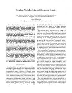
Consider two 4-input functions f and g. Both functions share variables a, b and c, while inputs d and e are the fourth input to functions f and g respectively. For this example we chose to put variables a and b on the rows of the truth table, as shown in Figure 6. If these two functions were to be synthesized separately, function f would have 2 basis vectors, while function g would have 3. However, when synthesized in tandem, there are only 3 basis vectors (2nd, 3rd and 5th column) for the two functions.
The second step of the algorithm is to perform a decomposition where some variables are shared by all functions and some are not. We create a list L of these functions and perform the next set of steps while the list is not empty. The list will shrink and grow as we synthesize functions, either because of the decomposition, or because some of the functions will be reduced to have fewer than k input variables and removed from the list.
We can now apply the same steps as for single output function synthesis to further optimize the logic function. In this case we can use basis and selector optimization algorithm to determine that a simpler function implementation can be found when an all 1s column is used instead of the 5th column.
The next step finds a subset of variables S that are used by the fewest number of functions in the set L. We take these functions out of the set L and synthesize their basis functions with respect to the input variables in S. The selector functions resulting from the decomposition are put back into the set L, because they can potentially share variables with functions in the set L.
The function f is synthesized as f=(a+b)drabc and shares its basis functions with g. For function g we find that the basis function from the 2nd column is used in column ce=10, the basis function from the 3rd column is used in columns ce={01, 10}, while the all 1s column is used in every column. Once we synthesize each basis and selector function, we can see that the synthesis of the all 1s column and its selector function simplify to a constant 1. A constant 1 input to a 3-input XOR gate reduces it to a 2-input XNOR gate. The resulting circuit is shown in Figure 7. While using shared inputs as the bound set can be beneficial, doing so will synthesize a circuit like a ripple-carry adder without a carry chain. For FPGAs however, it is better to use a carry chain because of its speed. To create ripple-carry structures in FLDS we use variables not common to all adder outputs as the bound set. Based on the above discussion we present a multi-output synthesis algorithm. The algorithm first considers the decomposition of multi-output functions by using least common variables of a set of functions as the bound set. By doing so it progressively decomposes the set of function to a point where they all share the same subset of variables and can be effectively decomposed together. The algorithm is presented in Figure 8.
If the above step completes the synthesis process, the algorithm terminates. Alternatively, we may end up with a set of functions in L that have the same support. In this case the algorithm performs decomposition by assigning shared variables to the bound set, utilizing balanced decomposition to keep the depth of the resulting logic circuit from increasing.
7. EXPERIMENTAL RESULTS In this section we present area, depth and compilation time results and contrast them with two academic synthesis systems: ABC [15] which utilizes structural transformations, and BDS-PGA 2.0 [6] that performs BDD based boolean optimizations. To obtain results using ABC each circuit was first converted to an AND/Inverter Graph using the strash command. It was then optimized using the resyn2 script and the resulting logic was mapped into 4-LUTs using ABC’s fpga command. To obtain results using BDS-PGA 2.0 a few more steps had to be taken, because it contains various flags to guide the synthesis process. The flags of interest are: • xhardcore (X) - enable x-dominator based XOR decompositions
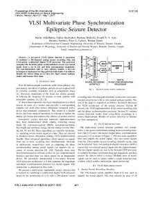
Table 1: Area Results Comparison Table for XOR-based Circuits Name 5xp1 9sym 9symml alu2 C1355 C1908 C3540 C499 C880 cordic count dalu des f51m inc my-adder rd53 rd73 rd84 sqrt8 sqrt8ml squar5 t481 xor5 z4ml
ABC BDS-PGA-2.0 FLDS LUTs Depth Time (s) LUTs Depth Time (s) X H S LUTs Depth Time (s) 40 114 85 150 75 107 363 77 112 304 42 255 1340 41 51 32 10 63 106 26 20 18 135 2 7
4 6 5 9 4 8 12 5 9 8 5 6 6 4 4 16 3 4 6 4 5 3 6 2 3
Total/Average Ratio
0.08 0.08 0.08 0.09 0.14 0.11 0.22 0.13 0.14 0.16 0.06 0.16 0.67 0.06 0.06 0.08 0.05 0.09 0.09 0.06 0.08 0.06 0.11 0.05 0.05
25 58 19 208 77 122 418 80 123 161 39 326 1338 32 45 33 12 15 25 22 26 18 70 2 6
4 6 6 12 6 9 14 4 9 18 5 9 7 5 4 16 3 4 5 4 6 3 6 2 3
2.96 1
0.07 0.54 0.17 0.82 3.87 0.91 2.99 3.42 1.21 1501 0.12 2.34 6.03 0.12 0.1 0.89 0 0.09 0.4 0.06 0.07 0.03 22.81 0 0.01
X X X X X X X X X X
X X X X X X X
X X X X X X
X X X X X X X X
1548 523
22 13 13 102 80 167 613 77 167 24 52 363 1155 18 51 35 7 11 15 12 12 15 5 2 8
4 4 4 7 6 13 17 6 11 5 5 9 8 4 4 16 2 3 3 3 3 2 2 2 3
0.02 0.031 0.051 0.082 0.036 0.077 0.236 0.035 0.067 9.735 0.036 0.128 5.456 0 0.035 0.051 0 0.015 0.031 0 0.02 0.015 0.078 0.015 0.02
16.27 5.5
CS 8 20 24 12 8 8 8 8 8 24 8 8 16 12 8 20 12 12 8 12 16 24 24 8 8
FLDS vs. ABC Area Depth -45.00 -88.60 -84.71 -32.00 6.25 35.93 40.78 0.00 32.93 -92.11 19.23 29.75 -13.81 -56.10 0 8.57 -30.00 -82.54 -85.85 -53.85 -40.00 -16.67 -96.30 0.00 12.50
0.00 -33.33 -20.00 -22.22 33.33 38.46 29.41 16.67 18.18 -37.50 0.00 33.33 25.00 0.00 0.00 0.00 -33.33 -25.00 -50.00 -25.00 -40.00 -33.33 -66.67 0.00 0.00
-25.26
-7.68
FLDS vs. BDS Area Depth -12.00 -77.59 -31.58 -50.96 3.75 26.95 31.81 -3.75 26.35 -85.09 25.00 10.19 -13.68 -43.75 11.76 5.71 -41.67 -26.67 -40.00 -45.45 -53.85 -16.67 -92.86 0.00 25.00
0.00 -33.33 -33.33 -41.67 0.00 30.77 17.65 33.33 18.18 -72.22 0.00 0.00 12.50 -20.00 0.00 0.00 -33.33 -25.00 -40.00 -25.00 -50.00 -33.33 -66.67 0.00 0.00
-18.76 -14.46
• sharing (S) - perform sharing extraction prior to decomposition • heuristic (H) - enable a heuristic variable ordering algorithm. Depending on these flags BDS-PGA 2.0 produces circuits with varying area. We performed a sweep across all combinations of the three parameters and recorded the best result, based first on area, then depth and finally on processing time. The resulting network was mapped into 4-LUTs using ABC [15].
Our results show that XOR-based logic can be reduced in size by 25.3% and 18.8% as compared to leading logic minimization tools like ABC and BDS-PGA 2.0, respectively. The depth of these circuits is also reduced by 7.7% and 14.5% respectively. The cost of this optimization is the increase in area for non-XOR based circuits. On average, FLDS generates 6.2% larger non-XOR circuits than ABC, and 4.8% larger than BDS-PGA 2.0.
The FLDS results were obtained by running our algorithm on each circuit, varying only a parameter called cone size (CS). This parameter specifies the maximum number of inputs to which a cone can be grown during the preprocessing step to create cones for synthesis to be used by FLDS. To obtain our result the cone size was set to 8, 12, 16, 20 and 24 inputs. The resulting circuit was mapped into 4-LUTs using ABC [15].
7.2 Discussion of Individual Circuits
7.1 Results Table 1 presents results obtained for 25 XOR-based circuits. The name of each circuit is given in the first column. The following three columns list the area (LUT-wise), depth and processing time results obtained using ABC [15] for each circuit. Columns 5 through 7 list the area, depth and processing time results for BDSPGA 2.0 [6]. The settings used to obtain the result for BDS-PGA are given in columns 8 through 10, which corresponds to a particular BDS-PGA flag (X, H, or S) as described in the previous section. For a given circuit an ‘X’ appears in these columns if the flag was turned on to generate the given result. In columns 11, 12 and 13 area, depth and processing time results obtained by FLDS system are shown. For each circuit, column 14 states the cone size used to generate cones for logic synthesis. The final four columns compare results obtained with FLDS to ABC (columns 15 and 16), and to BDS-PGA 2.0 (columns 17 and 18). To compare the results we used the following equation:
% difference = 100
(final − initial) MAX (initial, final)
(3)
This equation ensures that both gains and losses observed in the table of results are weighted equally.
Table 1 shows significant area savings for XOR-based logic function when using FLDS as compared to the aforementioned synthesis systems. The largest (percent wise) savings were observed for 9sym, cordic, sqrt8ml, and t481. 9sym is a circuit with a single 9 input logic function and includes a number of XOR gates. Interestingly enough, 9symml is exactly the same circuit, except with a different initial representation in the BLIF file. Both ABC and BDS-PGA 2.0 synthesized it much better than 9sym. In 9sym BDS-PGA 2.0 found the circuit to consist of 9 logic functions and for 9symml BDS-PGA found it to be a single output 9 input function. It created a single BDD for it and synthesized it well. FLDS was able to achieve a better result, because it found a better positioning for XOR gates. This difference stems from the fact that x-dominator based optimizations look for an XOR gate structure within a BDD, while FLDS creates an implementation where XOR gates are inherently present. This example shows that FLDS and BDD based decompositions are quite different. Another aspect of FLDS is the synthesis of multiple output functions. An example of a circuit that significantly benefitted from this approach was cordic. It consists of 2 functions sharing 23 inputs. The FLDS algorithm was able to minimize the area of this circuit by maximizing the reuse of logic expressions common to the two logic functions. The algorithm first created two cones of logic to represent the circuit and then determined the set of shared logic sub-functions that could be extracted to reduce circuit area. In contrast, neither ABC nor BDS-PGA partitioned
the circuit into two cones of logic. For example, BDS-PGA decomposed the circuit into 32 logic functions. As a result many more LUTs were need in the final implementation of this circuit. While in Table 1 the synthesis flags for this circuit do not include x-dominator decompositions usage, the results with this flag turned on were identical, except for the longer processing time. An example where the variable partitioning algorithm was particularly useful is the t481 circuit, which is a 16 input single output logic function. It is compactly represented in the FixedPolarity Reed-Muller form and can be synthesized into a minimal 5 4-LUT implementation. In FLDS the function was synthesized in 0.078 seconds, finding only two basis functions during a balanced decomposition. The variable partitioning algorithm was successful in finding a good assignment of variables, which allowed for a minimum area synthesis of the logic function. On the set of non-XOR based circuits our results were 4.8% larger than BDS-PGA and 6.2% larger than those generated by ABC. In terms of depth, BDS-PGA produced 6.2% better results here, while ABC was 16.5% better. However, numerous non-XOR circuits benefitted considerably from using FLDS. Examples of such circuits are ex5p, pdc, sao2, and ex1010, where the area was reduced by 50-80% with respect to both BDS-PGA 2.0 and ABC. The major reason for area reduction in those circuits was the multi-output synthesis capability offered by FLDS. In our research we also investigated the possibility of augmenting existing synthesis systems, such as ABC [15], with FLDS algorithms. We investigated the effect of using FLDS prior to the resyn2 script of ABC. We found this approach to improve ABC’s area results by 24% for XOR based circuits, and by 4% for nonXOR circuits. The depth results were improved by 16% for XOR circuits, while the non-XOR circuits suffered 1% depth penalty. This shows that the FLDS algorithm can augment ABC’s results.
7.3 Related Work The work closest to ours is factor [16]. In [16] a truth table matrix is decomposed into a product of 3 matrices using an approach based on Single Value Decomposition (SVD). Our method differs from [16], mostly in the approach to multi-output/multi-level synthesis. During multi-output decomposition the algorithm in [16] partitions variables to reduce the number of sub-functions for each output. However, the sub-functions for distinct outputs may still be linearly dependent. Our approach reduces the cost of final implementation of the circuit by removing linear dependencies. A work concurrent to ours [17] uses kernel extraction to generate leader expressions for decomposition. However, the approach in [17] hinges on the use of Reed-Muller form expressions, which limits its effectiveness for general logic functions. In contrast, FLDS uses BDDs as the underlying data structure, allowing our approach to be very efficient in terms of processing time. Also, using BDDs as a starting point allows FLDS to synthesize non-XOR logic effectively without sacrificing processing time.
8. CONCLUSION AND FUTURE WORK This paper presented a novel decomposition and synthesis technique that is very effective in reducing the area of functions that depend heavily on XOR gates. It performs well in extracting common sub-functions from a logic expression based on an XOR relationship. For non-XOR intensive logic circuits the technique suffers only a minor area and depth penalty. In both cases FLDS
performs logic synthesis rapidly, which is instrumental in the synthesis of large circuits. This synthesis technique is successful and will be further extended to include non-disjoint decomposition as well. Adding the ability to decide between the use of disjoint and non-disjoint decomposition will be a key target for FLDS.
9. ACKNOWLEDGMENTS We grateful to Dr. D. Singh, Dr. V. Manohararajah from Altera, and Prof. Z. Vranesic and Prof. J. Zhu from the University of Toronto for their feedback throughout the course of this research. We also thank Altera Corporation for funding this research.
10. REFERENCES [1] T. Sasao, Switching Theory for Logic Synthesis, Kluwer Academic Publishers, 1999, ISBN 0-7923-8456-3. [2] S. L. Hurst, D. M. Miller, J. C. Muzio, Spectral Techniques in Digital Logic, Academic Press, London, 1985. [3] E.M. Clarke, K. McMillan, X. Zhao, M. Fujita, and J. Yang, “Spectral transforms for large boolean functions with applications to technology mapping,” Proc. Of the 30th DAC, June 1993, pp. 54-60. [4] M. Karpovsky, “Harmonic analysis over finite commutative groups in linearization problems for systems of logical functions,” Inf. Contr., vol. 33, no. 2, Feb. 1977, pp. 142-165. [5] C. Yang, M. Ciesielski, and V. Singhal, “BDS: A BDD-Based Logic Optimization System,” Proc. of Int. Conf. on Comp. Design, 1999, pp. 626-631. [6] N. Vemuri, P. Kalla, and R. Tessier, “BDD-based Logic Synthesis for LUT-based FPGAs,” ACM Trans. On Design. Auto. of Electronic Devices, 2002, pp.501-525. [7] M. Perkowski and S. Grygiel, “A Survey of Literature on Function Decomposition,“ A Final Report for Summer Faculty Research Program, Wright Laboratory, Sponsored by Air Force Office of Scientific Research, Bolling Air Force Base, DC and Wright Laboratory, September 1994. [8] W. Wan and M. A. Perkowski, “A New Approach to Decomposition of Incompletely Specified Multi-Output Functions Based on Graph Coloring and Local Transformations and its Applications to FPGA Mapping,” Proc. Of. European DAC, 1992, pp. 230-235. [9] T. Sasao and J. T. Butler, “A Design Method for Look-up Table Type FPGA by Pseudo-Kronecker Expansion,” Proc. Of 24th Int. Symp. On MV Logic, 1994, pp. 97-106. [10] C. Tsai and M. Marek-Sadowska, “Multilevel Logic Synthesis for Arithmetic Functions,” Proc. of the 33rd DAC, 1996, pp. 242-247. [11] Y. Lai, M. Pedram, S. Sastry, “BDD-based Decomposition of Logic Functions with Application to FPGA Synthesis,” Proc. Of the 30th DAC, 1993, pp. 642-647. [12] C. Yang, V. Singhal, and M. Ciesielski, “BDD Decomposition for Efficient Logic Synthesis,” Proc. Of the Int. Conf. On Comp. Design, 1999, pp. 626-631. [13] H. Anton and C. Rorres, Elementary Linear Algebra, Applications Version, 7th Edition, Published by John Wiley & Sons Inc., 1994, ISBN 0-471058741-9. [14] R. E. Bryant, “Graph-based algorithms for Boolean function manipulation,” IEEE Trans. On Computers, vol. C-35, August 1986, pp. 677-691. [15] Berkeley Logic Synthesis Group, ABC: A System for Sequential Synthesis and Verification, December 2005 Release. URL: http://www.eecs.berkeley .edu/~alanmi/abc. [16] TT Hwang, R. M. Owens, and M. J. Irwin, “Exploiting Communication Complexity for Multilevel Logic Synthesis,” IEEE Trans. On CAD, vol. 9, No. 10, Oct 1990, pp. 1017-1027. [17] A. Verma, P. Brisk, and P. Ienne, “Progressive Decomposition: A Heuristic to Structure Arithmetic Circuits,” Proc. Of the 44th IEEE Des. Auto. Conf, June 4-8, 2007, pp. 404-409.