the methods uses an extended Kalman filter and the other uses a linear Kalman filter whose application is made possible by using an augmented state system ...
IEEE ISIE 2005, June 20-23, 2005, Dubrovnik, Croatia
Fusion of Odometry with Magnetic Sensors Using Kalman Filters and Augmented System Models for Mobile Robot Navigation António Surrécio, Urbano Nunes, and Rui Araújo Institute of Systems and Robotics, University of Coimbra Polo II, 3030-290, Coimbra, Portugal
Abstract: This paper presents a comparative study of two data fusion methods for high precision mobile robot’s pose estimation. Odometric data, provided by wheels encoders, are fused with data from magnetic markers detection. One of the methods uses an extended Kalman filter and the other uses a linear Kalman filter whose application is made possible by using an augmented state system model. The measurement system is composed by wheel encoders and two magnetic sensing rulers, one on the front and the other on the rear of the mobile robot, for magnetic markers detection. Simulation results with a very realistic approach are presented.1
I.
INTRODUCTION
Odometry is a method of localization for land vehicles used with generality, based on wheels encoder’s data. This method however, based on dead reckoning, produces cumulative errors which in case of no compensation, result over time in an appreciated pose deviation. One possible way of errors compensation is the use of fusion of odometry with other sensorial data which makes possible its correction. The use of magnetic markers embedded in the ground, may supply the kind of necessary information for the odometric data calibration, in a way, to have available a pose estimation of the vehicle with the required precision for autonomous navigation. Sensor fusion regarding mobile robot localization should be turning to computing algorithms which produce its optimal estimation. The Kalman filter and its variants, verify this requirement being for this reason largely used. The odometry and measurement models, involved in pose estimation by using landmarks such as magnetic markers, are nonlinear, and therefore the use of an extended Kalman filter (EKF) would become inevitable in the fusion process. However, by using an augmented state a linear Kalman filter (LKF) can be applied instead of the EKF. This paper presents a comparative study of two data fusion methods for high precision vehicle´s pose estimation. One based on an
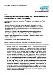
EKF and another using a LKF applied to an augmented state system model. Many laser and vision based systems have been developed for absolute positioning using landmarks. Position measurement using magnetic markers has proved to be one promising technology for ground vehicle autonomous guidance and control. The Californian project PATH, has given remarkable contributions in the development of a reference system based on magnets for vehicle lateral guidance [2], [5], [7]. In our work magnetic markers are used as landmarks, however the described fusion processes can be similarly applied for other kinds of landmarks like environment features detected by vision or laser scanner. The paper addresses research regarding the development of a navigation system, for autonomous robot navigation, structured as depicted in Fig. 1. The overall navigation system is divided in three main subsystems, which are designated by path-following controller (PFC), vehicle’s pose estimator (VPE) and multi-target detection and tracking system (MTDTS). The PFC and MTDTS systems are described in [1] and [4], respectively. New studies regarding VPE [3] are presented in this paper.
This work was partially supported by the Portuguese Science Foundation (FCT) and POSI, grant: POSI/41618/SRI/2001.
0-7803-8738-4/05/$20.00 ©2005 IEEE
1551
Laser scanner
MTDTS
Path Genera tor
Range-bearing Data
Path Following Controller
Vehicle’s Pose Estimator
Vehicle & Encoders
Encoders
Magnetic sensors
Figure 1. Architecture of the autonomous navigation system
y
yR
t e xt
L
D
d
dr
yk
sensing rulers measures are treated as measurements and (∆, ω) define the inputs of the EKF data fusion process.
xR
Tk
(1) System Model: the system model is defined by the kinematic nonlinear equations (1), with state vector xk = [xk yk θk]T and input uk = [∆ ω ]T, which can be written in the compact form (including noises):
FMR
O
xk+1 = f (xk, uk,) + υk
r
where υk denotes the system noise, with associated covariance matrix Q, which models the uncertainties of the odometry model.
RMR
xk
x
(2) Measurement Model (example for the FMR): the magnetic ruler when detects magnet i outputs the measure dr (see Fig. 2), which is the distance between the marker with known position (xmi, ymi) and the magnetic-sensing ruler central point. The measurement model is given by:
Figure 2. Mobile robot configuration and measurement model. The mobile robot is equipped with a FMR and a RMR.
II.
ODOMETRY MODEL
A circular differential-drive wheeled mobile robot (WMR), with body radius L and wheels radius r is considered in this study, as depicted in Fig. 2. The WMR is equipped with two magnetic sensing rulers: a front magnetic ruler (FMR) and a rear magnetic ruler (RMR). Let the mobile robot position be represented by its central point O with Cartesian coordinates (xk, yk) at time tk . The local coordinates system ^OxR yR ` is fixed to the WMR.
tk . Assuming that the robot’s motion is locally circular, its pose evolution at step k is described by the following odometric model: ⎧ xk �1 xk � ' cos(T k � Z / 2) ⎪⎪ ⎨ yk �1 yk � ' sin(T k � Z / 2) ⎪ ⎪⎩ T k �1 T k � Z
= ⎡⎢ xk � d cos (T k � D ) ⎤⎥
zk
⎣ yk � d sin (T k � D ) ⎦
(5)
where d is the distance between the magnetic marker position and the origin of the mobile robot referential d
d r � L2
(6)
D
⎛d ⎞ arctan ⎜ r ⎟ ⎝ L⎠
(7)
2
and
The linear velocity of the robot is in the direction of the xR -axis, and T k represents the heading direction at time
Equation (5) defines the nonlinear measurement model which can be written in the compact form (including noise) zk = h( xk ) + σk
(1)
(8)
where σk is considered zero-mean white noise with covariance matrix R.
where ∆ is the arc length and ω the elementary rotation from state k to k+1. Assuming that there is no wheels slippage, then '
' r � 'l 2
(2)
ω
∆r � ∆l 2L
(3)
(3) EKF-based pose estimation: the EKF algorithm is composed by the following prediction and correction stages: Prediction stage xˆ k�
where ∆r and ∆l are calculated using the right and left encoders measurements, respectively. III.
(4)
� k
P
(9) T
A k Pk �1 A k � Q
(10)
where matrix Ak is calculated as the following Jacobian of the system f(.) function:
FUSION OF ODOMETRY AND MAGNETIC SENSORS USING EKF
This section describes the fusion of odometry and landmarks by means of an EKF. The vehicle’s pose defined by the Cartesian coordinates (x,y) and heading (θ) are the state variables of the system model. The magnetic
f �xˆ k �1 , u k
Ak
⎡1 0 � ∆ sin (θ k � ω / 2)⎤ ⎢0 1 ∆ cos(θ � ω / 2) ⎥ k ⎥ ⎢ ⎥⎦ ⎢⎣0 0 1
This stage is computed for all sampling times.
1552
(11)
Correction stage Once a magnet i is detected, its known position >xmi y mi @T and its corresponding measure dr are zk
(3) Measurement Model for the RMR: due to the different geometrical location, the RMR mesaurement model becomes slightly different yielding:
used in the following correction stage:
H k Pk H k � R
Sk
Pk� H Tk S k
Kk xˆ k Pk
T
�
xˆ
� k
(12)
�1
�
(13) � k
� K k z k � h(xˆ )
(15)
where I is a identity matrix and the measurement matrix H is calculated as the following Jacobian of the measurement h(.) function: ⎡1 0 � d sin (θ k � α )⎤ ⎢ ⎥ ⎣0 1 d cos(θ k � α ) ⎦
IV.
(16) Prediction stage
xˆ �k � k
P
(1) System Model: similarly as done is [8], we augment the system state with the purpose of getting odometric and measurement models which are linear in the states. This means that it is possible, by applying some trigonometric relations to (1), to isolate the state from the dynamic matrix in the system model (17). Denoting cos(θk) = ck and sin(θk) = sk, (1) can be written as (including system noise):
x k �1
(19)
(4) LKF-based pose estimation: since the system and measurement models were made linear in the states (17)(18). This motivates the study of the application of an LKF in the fusion process of pose estimation using odometric data and absolute positioning data from the magnetic sensing rulers. The LKF algorithm is composed of the following prediction and correction stages:
FUSION OF ODOMETRY AND MAGNETIC SENSORS USING LINEAR KF
⎡1 ⎢0 ⎢ ⎢0 ⎢ ⎣0
� σk
H k xk � σk
(14)
(I � K k H k ) Pk�
Hk
⎡1 0 � d r ⎢0 1 � r ⎣
zk
⎡ xk ⎤ � r ⎤ ⎢⎢ y k ⎥⎥ d r ⎥⎦ ⎢ s k ⎥ ⎢ ⎥ ⎣ ck ⎦
(20) T
A k Pk �1 A k � Q
(21)
where A k is the system dynamic matrix (17) and Q the system noise covariance matrix. Correction stage Once a magnet i is detected, its known position
zk
>xmi
y mi @ and its corresponding measure dr are T
used in the following correction stage:
0 � ∆sin(Z/2) ∆cos(Z/2)⎤ ⎡ x k ⎤ 1 � ∆cos(Z/2) ∆sin(Z/2) ⎥⎥ ⎢⎢ y k ⎥⎥ � υk cos(Z/2) 0 sin(Z/2) ⎥ ⎢ s k ⎥ ⎥⎢ ⎥ 0 sin(Z/2) cos(Z/2) ⎦ ⎣ c k ⎦
A k x k � υk
A k xˆ k �1
Sk
�1
Kk
Pk� H Tk S k
xˆ k
xˆ �k � K k z k � H k xˆ �k
Pk
(17)
(22)
T
H k P k� H k � R
�
(23)
(I � K k H k ) Pk�
(24) (25)
A. Data Association (2) Measurement Model for the FMR: for the augmented state, using (7) and after some mathematical manipulation, we can transform (5) into the following linear measurement model:
zk
⎡1 0 � d r ⎢0 1 r ⎣ H k xk � σ k
⎡ xk ⎤ r ⎤ ⎢⎢ y k ⎥⎥ d r ⎥⎦ ⎢ s k ⎥ ⎢ ⎥ ⎣ ck ⎦
Most existing techniques to implement the data association process are based on the inovation sequence and its predicted covariance. The innovation sequence υk relates observations zk to the predicted observations zˆ k υk
� σk
z k � h (xˆ k� )
(25)
Let the normalized innovation distance be defined as dk
(18)
υ k T S k �1 υ k
(26)
where S k is the innovation covariance matrix defined in (12) and (22). Note that if the innovation υk has a Gaussian distribution, then d is a random variable following the χ2 distribution. The innovation sequence is the basis of the gate validation technique which accepts 1553
the observations that are inside a fixed region of a χ2 distribution, and rejects the observations that make the innovation fall outside these bounds. This procedure is achieved by comparing the scalar obtained in (26) with a threshold value that is determined from the χ2 distribution table. V.
Figs. 7 and 8 respectively show, the position and orientation errors of both fusion algorithms for the path following experiments shown in Fig. 5. The following Q covariance matrices were used in the simulations, respectively for EKF and LKF fusion algorithms:
SIMULATION RESULTS
The two data fusion algorithms were simulated using the control system of Fig. 4, and a circular WMR with body radius L=12.85cm and wheels radius r=3.8cm. The magnetic markers were regularly placed along the closed path (see Fig. 6) with approximately 1m distance between them. For each sampling time, the Path Generator module computes from the pre-planned path, the next desired pose for the WMR that is computed for a given control point, which is located at a given lookahead distance in front of the robot. Module Te transforms the pose error, at the control point, from world to the local coordinate system. A Kanayama controller [6] was used in the Steering Controller. The Odometry module computes the pose estimation using equations (1)-(3) having as inputs the wheel encoders measurements. The data fusion algorithms, EKF and LKF based algorithms described in sections III and IV, were implemented as the VPE module. In order to check the performances of the data fusion algorithms, a loop was included in the simulation model (see Fig. 4) to compute the real robot pose, and therefore allowing computing the error pose sequence for each simulation run. Besides the encoder’s measurements, the Real Pose Computation module receives information about all the disturbances injected in the control system. Several simulations are reported in this section, all of them concerned with the path-following control of a WMR moving along a predefined closed path (see Fig. 6). Fig. 3 shows the disturbance signals injected into the control system during each run of the WMR along its path: (1) Gaussian white measurement noise added to the encoder data with variance of 1; (2) Gaussian white noise added to the magnetic sensing rulers data with variance of 0,05; (3) impulsive disturbances to simulate wheels slippage of 8cm; and (4) a systematic error with magnitude of 0.2mm in the wheels radius. Fig. 5 shows simulation results of a path following, with the control system affected by the described disturbances, in three situations: (1) without data fusion correction; (2) EKF-based data fusion; and (3) LKFbased data fusion. In order to simulate the data association process, four false magnetic landmarks were placed as depicted in Fig.5. The false magnets are detected but not known in the environment model, and are used to simulate false detections. When one of these magnets are detected, the association to the nearest known magnet landmark yields a high innovation absolute resulting in the false magnet being discarded in the validation gate threshold process as illustrated in Fig.6.
Q1EKF
diag (100,100, S / 9)
Q1LKF
diag (100,100, cos(S / 9),sin(S / 9))
where diag represents a diagonal matrix. The R covariance matrices are identity matrices in both algorithms. Tables I-III show simulation statistics comparing the performances of EKF and LKF algorithms. In the corresponding simulations, were used the following Q matrices in the case of EKF algorithm: Q 2EKF
diag (10,10, S /15) ,
Q3EKF
diag (1000,1000, S / 5) ,
and the following ones in the case of the LKF algorithm: Q 2LKF
diag (10,10, cos(S /15),sin(S /15)) ,
Q3LKF
diag (1000,1000, cos(S / 5),sin(S / 5)) ,
The experimental reference velocities assigned in the experiments were v1 = 40cm/s, v2 = 150cm/s and v3 = 60 cm/s for both algorithms. Tables show mean and variance values for position and orientation errors, steering oscillation measures, velocity, acceleration, and jerk. The high values verified in the variances of accelerations and, more significantly in jerks are due to the impulsive disturbances injected to the system with the purpose of simulating wheels slippage.
Figure 3. Disturbances injected to the control system to simulate wheels slippage (cm), and measurement white noise (encoders and magnetic sensing (cm)).
1554
Xd
Path Generator
⎡eRx ⎤ ⎢e ⎥ ⎢ Ry ⎥ ⎣⎢eRT ⎦⎥
Te
+
Steering Controller
⎡ vc ⎤ ⎢Z ⎥ ⎣ c⎦
⎡⎤ ⎢Tr ⎥ ⎢T ⎥ ⎣ l⎦
Mobile Robot
-
^ X
Data Fusion
Odometry
VPE dr
Xe
Pose Error
X
Magnetic sensors
Real Pose Computation
+
Disturbances
Figure 4. Simulation model of the path-following control of a WMR with a data fusion based pose estimation module, which combines odometry and ˆ are the real, error , desired, and estimated pose vectors, absolute positioning data provided by magnetic markers detection, where X, Xe, Xd and X respectively. 1000 Starting Point
900
False Magnetic Markers Without Correction LKF EKF
800 700 600
cm
500 400 300
Movement Direction
200 100 0
0
100
200
300
400
500
600
700
800
900 1000
1100 1200
X (cm)
Figure 7. WMR position errors concerning the simulations depicted in Fig.5 for EKF and LKF algorithms.
Figure 5. Simulation runs for a linear reference velocity of 40 cm/s.
0.08
EKF LKF
0.06
0.25
0.04
EKF LKF
0.2
rads
0.02
0.15
0
-0.02
0.1
-0.04 -0.06
EKF threshold
0.05
-0.08 LKF threshold
0
0
10
20
30 secs
40
50
-0.1
60
Figure 6. Performance of the validation gate to discriminate between valid and invalid magnetic landmarks
0
10
20
30 secs
40
50
60
Figure 8. WMR orientation errors concerning the simulations depicted in Fig.5 for EKF and LKF algorithms.
1555
exhibit good performances and showed to be robust in dealing with different sources of disturbances. The data association process is effective in dealing with problems of erroneous measurements and consequently makes the control system relatively immune to some kind of undesirable magnetic interferences. Real experiments are being performed showing the effectiveness of the overall navigation control system [1]. The same fusion algorithms will be applied in autonomous navigation based in the detection of other kind of landmarks like environment features. Moreover the VPE module will be enhanced through the integration of INS data.
TABLE I STATISTIC VALUES FOR EKF SIMULATION RUNS v1
Q1
e(x,y)
(cm)
eθ
(rad)
Osc (rad/s)
v (cm/s)
a
(cm/s2)
jerk
(cm/s3)
ē σ2 ē σ2 ē σ2 ē σ2 ē σ2 ē σ2
v1
v2
Q2
Q3
2.7117
25.0730
3.1902
2.4672
2.1369
29.9223
2.9945
1.9496
-0.0259
-0.0741
-0.0064
-0.0164
0.0267
0.0803
0.0260
0.0162
0.1056
0.3442
0.1060
0.1060
0.3947
0.8391
0.3375
0.3214
46.2578
148.5247
46.1912
46.2357
1.2401
7.9347
1.2739
1.2910
0.0450
0.3106
0.0427
0.0425
6.1628
23.9254
6.1203
6.1255
-0.1281
7.8024
-0.1313
-0.1298
844.0145
1152.5618
844.5204
844.0743
REFERENCES [1]
TABLE II STATISTIC VALUES FOR LKF SIMULATION RUNS
e(x,y)
(cm)
eθ
(rad)
Osc (rad/s) v (cm/s)
a (cm/s2) jerk (cm/s3)
ē σ2 ē σ2 ē σ2 ē σ2 ē σ2 ē σ2
[2]
v1
Q1 v1
v2
Q2
Q3
2.4051
2.5840
2.4105
2.4759
2.0950
2.2945
2.0436
2.0425
-0.0182
-0.0231
-0.0171
-0.0215
0.0234
0.0110
0.0227
0.0184
0.1063
0.3370
0.1060
0.1065
0.3689
0.6700
0.3462
0.3419
46.2192
152.1232
46.2206
46.2577
1.3059
6.1279
1.3026
1.2716
0.0340
0.4677
0.0415
0.0433
6.1979
17.1478
6.1590
6.1126
-0.1047
7.5393
-0.1267
-0.1336
843.0949
1213.0674
843.6411
844.0786
[3]
[4]
[5] [6]
TABLE III COMPARATIVE STATISTIC VALUES FOR A SIMULATION WITH APPROXIMATELY 10 TURNS (500 S OF RUN TIME) IN THE PATH OF FIG 5.
e(x,y)
(cm)
eθ
(rad)
Osc (rad/s)
v (cm/s)
a
(cm/s2)
jerk
(cm/s3)
ē σ2 ē σ2 ē σ2 ē σ2 ē σ2 ē σ2
VI.
EKF (Q1, v3)
LKF (Q1, v3)
2.4969
2.4988
2.2016
2.1584
-0.0130
-0.0230
0.0201
0.0157
0.1586
0.1587
0.4160
0.4093
65.3273
65.4206
2.2831
2.1970
-0.0071
-0.0114
6.6352
6.4680
-0.0215
-0.0350
831.9983
834.5214
[7]
[8]
CONCLUSIONS
This paper describes the development and simulation results of a data fusion method for odometric data correction through a LKF-based methodology using an augmented system state. Comparison results with an EKF-based pose estimation are shown. Both methods
1556
L. Conde Bento and Urbano Nunes, “Autonomous navigation control with magnetic markers guidance of a cybernetic car using fuzzy logic,” Journal of Machine Intelligence & Robotic Control, Cyber Scientific, Japan, in press. Han-Shue Tan, Bénédicte Bougler, “Vehicle Lateral Warning, Guidance and Control Based on Magnetic Markers: PATH Report of ASHRA Smart Cruise 21 Proving Tests,” California PATH Working Paper, UCB-ITS-PWP-2001-6. Institute of Transportation Studies, University of California, Berkeley, 2001. Márcio Barata, Urbano Nunes, L. Conde Bento, and Abel Mendes, “Data Fusion of wheel encoders and magnetic sensors for autonomous vehicles navigation,” 6th Portuguese Conf. on Automatic Control (Controlo 2004), Faro, Portugal, 2004. Abel Mendes and Urbano Nunes, “Situation-based multi-target detection and tracking with laserscanner in outdoor semistructured environment,” IEEE/RSJ Int. Conf. on Intelligent Robots and Systems (IROS 2004), 88-93. Sendai, Japan, 2004. W. Zhang, B. Parson, and T. West, “Intelligent roadway reference system for vehicle lateral control,” Proc. of the 1990 American Control Conf., San Diego, CA, USA, 281-286, 1990. Y. Kanayama, Y. Kimura, and F. Miyazaki, “A stable tracking control method for a non-holonomic mobile robot,” IEEE/RSJ Int. Workshop on Intelligent Robots and Systems, 1236–1241, 1991. Yunchun Yan and Jay A. Farrell, “Magnetometer and differential carrier phase GPS-aided INS for advanced vehicle control,” IEEE Trans. on Robotics and Automation, vol.19, no.2, pp. 269282, 2003. Xu Zezhong, and Liu Jilin. “Mobile robot localization using linear system model,” 1st Int. Conf. on Informatics in Control, Automation and Robotics (ICINCO 2004), pp. 243-248, Setúbal, Portugal, 2004.