370 Int. J Latest Trends Computing
Vol-2 No 3 September, 2011
Fuzzy Logic and Neural Network Control Systems for Backing up a Truck and a Trailer P. D. C. R Jayarathna1, J. V Wijayakulasooriya2 and S. R Kodituwakku3 1,3
Department of Statistics and Computer Science, Faculty of Science, University of Peradeniya, Sri Lanka. 2 Department of Electrical and Electronic Engineering, Faculty of Engineering, University of Peradeniya, Sri Lanka. 1
[email protected],
2
[email protected],
Abstract: Today, computer control systems have achieved a highest position of their applicability through large scale industries to smaller activities such as controlling a movement of an object. Especially many researches are being carried out to develop control systems to automate the movements of vehicles as it is performed by a human being. This paper presents control systems to control the backing up motion of a truck and trailer vehicle into a particular location such as a loading dock. Salient feature of these systems is that it can be applied to any vehicle system which has a trailer attached to it. Two separate control systems are used to achieve the desired goal. In the first approach, the system uses fuzzy logic while the second approach uses an artificial neural network for the same purpose. The proposed controllers are tested for different initial positions and orientations of the truck and the trailer using a simulation model implemented with the MATLAB tool boxes. Comparisons of the results obtained are also presented. Under the conditions considered for the simulation it is observed that the fuzzy logic based control system is capable of controlling the vehicle within a larger area than that of the neural network based control system. Keywords: Computer Control System, Backing Up, Tuck and Trailer, Fuzzy Logic, Artificial Neural Network
1. Introduction To drive a vehicle accurately a person needs to have a good practice. Especially more skills are needed to drive a vehicle backward into a particular position precisely. However, if it is a Truck and a Trailer vehicle things become much more complicated. In backing up a vehicle into a particular position such as a loading dock, the usual way of driving an ordinary vehicle such as a car in backward direction can not be directly applied for backing up a truck with a trailer attached to it. Basically there are three problems associated with the backward motion of a truck and a trailer vehicle which cause difficulties for a driver. First one is that the driver does not have a direct control over the trailer. Only possibility is to control the truck so that the trailer which is attached to it moves towards the dock with appropriate orientations. Another problem in this process is that when the relative angle of the truck with respect to the trailer is large, the driver can see only one side of the vehicle. There is no way for the driver to get a good idea about what is happening at the other side of ______________________________________________________________ International Journal of Latest Trends in Computing IJLTC, E-ISSN: 2045-5364 Copyright © ExcelingTech, Pub, UK (http://excelingtech.co.uk/)
3
[email protected]
the vehicle even with the side view mirrors until the truck aligns with the trailer. Furthermore, when the angle between the truck and the trailer is very large it leads to a “jackknife” situation [5], [7] which may cause the trailer to detach from truck. When professional truck drivers back up the vehicle they always try to keep the relative angle between the truck and the trailer as less as possible. To achieve this, drivers always back up the vehicle by repeatedly switching between forward and backward motions until the vehicle aligns properly and finally backing up to the destination. It is more difficult when the trailer needs to be backed up with no forward movements permitted. The specific problem treated in this research is of this kind. That is the goal of this project is to develop a computer controller system to back up a truck and a trailer into the loading dock with only backward motion. The purpose of any controller system is to observe the values of the inputs and to produce the values of the outputs according to the relationships defined between them. To control the movement of an object this process needs to be performed repeatedly until the goal is met. When it is not possible to model mathematically there are two widely used approaches of developing computer controller systems: Fuzzy Logic and Neural Networks. In this research, two controllers for backing up the truck and trailer are designed and implemented using these two techniques separately. Also a simulation model is created using MATLAB to demonstrate and compare the performances of the controller systems.
2. Related Work Several attempts have been made to realize a control system for backing up a truck and a trailer into a particular position. Fuzzy Logic is the method that has been used widely in most of the control systems [2]-[7] while Neural Network approaches have also been investigated [1], [2]. Some control systems have been designed to control both the forward and backward motion of the vehicle to reduce the complexities in backing up into a particular location when the clearance between the trailer and the position of the dock is not adequate [5]. In some other attempts [2], [3], it has been assumed that there is an enough space for the vehicle to move before it can be aligned to the final destination point so that only the backward motion of the vehicle is enough to reach the goal. However, the control system would not be able to guide the vehicle into the desired
371 Int. J Latest Trends Computing
position from an initial state which is closer to the final position unless it is only a direct movement without any turning of the vehicle. In addition, as discussed in [2] the comparisons of the two methods, fuzzy logic and artificial neural networks have also been made. However, almost all of the existing fuzzy logic control systems have designed considering only the distance in x direction from the end point of the vehicle to the position of the dock assuming to have enough space in Y direction. The systems proposed in this paper considered the both directions in modeling the controller system.
Vol-2 No 3 September, 2011
into a single fuzzy set. Fuzzy rules are fired in parallel, which is one of the important aspects of an FIS. In an FIS, the order in which rules are fired does not affect the output. The defuzzifier maps output fuzzy sets into a crisp number. Given a fuzzy set that encompasses a range of output values, the defuzzifier returns one number, thereby moving from a set to a crisp number. Several methods for defuzzification are used in practice, including the centroid, maximum, mean of maxima, height and modified height defuzzifier. The most popular defuzzification method is the centroid method which calculates and returns the center of gravity of the aggregated fuzzy set.
3. Materials and Methodology In order to develop a controller system two candidate soft computing techniques are used. These techniques are summarized here. 3.1.
Fuzzy controller Knowledge Base
Input Fuzzification
Materials
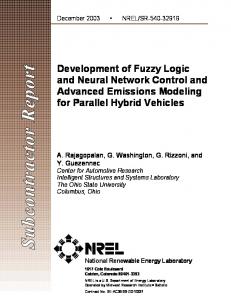
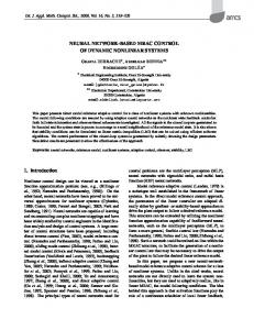
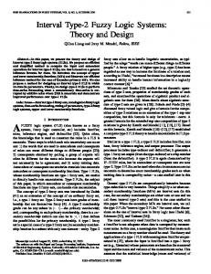
Fuzzy Logic and Fuzzy Logic controllers Fuzzy logic is a form of multi-valued logic derived from fuzzy set theory to deal with reasoning that is approximate rather than precise. Therefore fuzzy logic is widely used when an approximated value is adequate rather than observing highly accurate value. Since it is not required to park the trailer in the dock with high accuracy fuzzy logic is used to develop the controller. A fuzzy inference system (FIS) essentially defines a nonlinear mapping of the input data vector into a scalar output, using fuzzy rules. The mapping process involves input and output membership functions, fuzzy logic operators, fuzzy if then rules, aggregation of output sets, and defuzzification. Also a FIS with multiple outputs can be considered as a collection of independent multiinput, single output systems. There are four components in a Fuzzy Inference System: the Fuzzifier, Inference Engine, Knowledge Base and Defuzzifier. These components are shown in figure 1. The knowledge base contains the linguistic rules that have to be designed considering the knowledge of an expert of the field of consideration. It is also possible to extract rules from numeric data. Once the rules have been established, the FIS can be viewed as a system that maps an input vector to an output vector. The fuzzifier maps input numbers into the corresponding fuzzy memberships. This is required in order to activate rules that are in terms of linguistic variables. The fuzzifier takes input values and determines the degree to which they belong to each of the fuzzy set via membership functions. The inference engine defines mapping from input fuzzy sets into output fuzzy sets. It determines the degree to which the antecedent is satisfied for each rule. If the antecedent of a given rule has more than one clause, fuzzy operators are applied to obtain one number that represents the result of the antecedent for that rule. It is possible that one or more rules may fire at the same time. Outputs for all rules are then aggregated. During aggregation, fuzzy sets that represent the output of each rule are combined
Defuzzification Inference Engine
Output
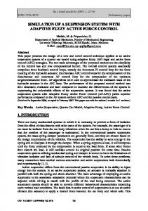
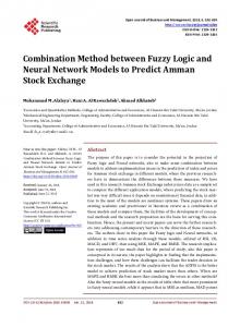
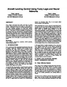
Figure 1. Components of a fuzzy logic controller. Artificial Neural Network An artificial neural network is an attempt to simulate the manner in which the human brain interprets information as determined by current knowledge of biology, physiology, and psychology. Neural networks are fault tolerant, exhibit the ability to learn and adapt to new situations, and have the ability to generalize based on a limited set of data. Neural networks can be used to solve highly nonlinear control problems. It is a system with inputs and outputs and is composed of many simple and similar processing elements. Each of the processing elements has a number of internal parameters called weights. Changing the weights of an element will alter the behavior of the whole network.
X
Σ
f(x)
Y
1 Figure 2. Adaline The processing element used in an artificial neural network is known as the adaptive linear neuron or Adaline. Figure 2 illustrates a model of the artificial neural network. It has an input vector X={xi}, which contains n number of components, a single output Y, and a weight vector W={wi}, which also contains n number of components. Then the output Y equals to the sum of inputs multiplied by the form of activation function f(x) according to the equation (1).
372 Int. J Latest Trends Computing
Vol-2 No 3 September, 2011
n 1 Y s( X ) f wi xi i 0
w (1)
The goal of a neural network is to choose the weights of the network to achieve a desired input and output relationship. This process is known as the training of the network. When the weights are kept constant the output vector only depends on the current input vector and is independent of the past inputs. During the training process the Adaline is presented with an input X, which causes its output to be y(X). The Adaline outputs d(X) instead of y(X) so that the weights are adjusted to cause the output to be something more close to d(X) or to reduce the difference between the actual output y(x) and the desired output d(X) when X is presented as the input at the next time. Many input, desired output pairs are used in the process of training of the weights. After the each cycle of training a performance measure is performed to measure the acceptability of the current output of the neural network. One of the widely used measures of the performance of an Adaline is the mean squared error ( J ). If the observed error is greater than some threshold value the gradient descent method illustrated by equations (2) and (3) is applied to adjust the weights.
n1 J E d ( x) f wi xi i 0
wi.new wi.old 2xi
2
(2) (3)
Where,
d ( x) y( x) f s( x)
and f s is the first derivative of the function
f s
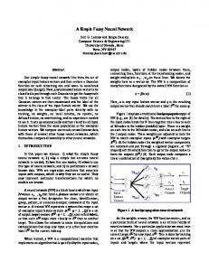
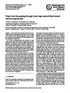
This approach of Adaline can solve only linear type problems. But to solve nonlinear problems as it appears in most of the real world situation Adalines are connected together to from multilayer neural networks as shown in figure 3. This is also known as the Layered feed forward neural network. Here the outputs of a one layer are connected to the inputs of the next layer so that the output will be forwarded through the layers up to the output layer. It has been proven that a network consists of only two layers of Adalines can implement any nonlinear function.
Σ
f(x) . . .
1 X Σ
. . .
Σ
Y
f(x)
1 Figure 3. Multilayer neural network Because of the interconnection of the single adalines to make up the multi layered neural network it is necessary to use a more complex training algorithm known as the Back Propagating learning algorithm. Here the weight adjustments are not straight forward as in single layer Adeline because the real output is associated with the weight values of the immediate layer before the output layer which is know as the hidden layer which does not acquire the real input of the system causing the necessity of sending the error backward though the previous layers of neurons to make the weight adjustments. The back propagation algorithm converges to a set of weights that minimizes the meansquare error. Similar to the single Adaline network, the equivalent error δ is defined for each Adaline in the network. And if there are j number of inputs connected to the output of the Adaline m, the equations (4) and (5) calculates the equivalent error of the Adaline m in the output layer and the equivalent error of the Adaline m in any other layer.
m d m ( x) ym ( x) f sm ( x) (4)
m f sm ( x) j w jm
(5)
j
Where, wjm is the weight of the connection from output of Adaline m to the input of Adaline j. 3.2. Methodology As the first step the inputs for the control systems are decided considering the position and orientation of the vehicle as shown in the figure 4. Then the objective of the control systems are to guide the rear end point of the trailer (xt,yt) on to the position (xdock, ydock) to park it perpendicular to the dock. That is the value of the angle Φt had to be 90 degrees when the trailer is parked. However, the final position or the orientation of the truck is not taken in to concern as long as it is attached to the trailer and the trailer is reached the expected final configurations. The entire process is carried out in three different stages as design of fuzzy logic control system, design of neural network control system and the design of simulation model to demonstrate and compare the effectiveness of the designed control systems.
373 Int. J Latest Trends Computing
Vol-2 No 3 September, 2011
θ
Since it is complicated to define the rule base for a fuzzy logic system with four input variables two separate fuzzy logic systems are used to obtain the steering angle for the current state of the vehicle. First one is a mamdani type fuzzy system which takes xdist , ydist and Φt as the inputs and produces a value for the relative angle between the truck and the trailer, (ΦcΦt)req, which is required for the trailer to be moved to the dock from the current position of the trailer. Then the output obtained from the first fuzzy logic system and the current value of the relative angle between the truck and the trailer (Φc- Φt)curr are used as input to the second sugeno type fuzzy system as shown in the figure 6 which calculates the necessary steering angle (θ) as the output.
Φc Φ c- Φ t y Φ
xdist
Φt (xt,yt)
ydist
xdist ydist
x
Φt
(xdock,ydock) Figure 4. Input and output variables of the fuzzy logic control systems 3.2.1 Fuzzy Logic Control System According to the figure 4 the distance to the rear end point of the trailer along the positive x direction (xdist) and along the positive y direction (ydist) from the position of the dock (xdock,ydock), the orientation of the trailer with respect to the positive x direction (Φt) and the relative angle between truck and trailer (Φc - Φt) are the inputs to the control system to produce the steering angle (θ) of the truck as the output. A single fuzzy logic controller system which takes four input variables and produces one output is designed as shown in the figure 5. The working range of the controller system is taken as a square area of 100 meters a side. Then the ranges of each input and the output are taken as shown in the table 1, in the same measurement scales as they appear in a real truck and trailer vehicle. All measurements of lengths are taken in meters and the angles in degrees. xdist ydist Φt (Φc- Φt)
Fuzzy Logic
θ
Figure 5. Design of the single fuzzy logic controller The input and output of the system are given in Table 1. Table 1. Inputs and outputs of fuzzy logic system Variable xdist ydist Φt (Φc- Φt) θ
Type Input Input Input Input Output
Range -50 to +50 0 to +100 -180 to +180 -90 to +90 -60 to +60
Unit meter meter degree degree degree
(Φc- Φt) curr
Fuzzy Logic 1
(Φc- Φt)req
Fuzzy Logic 2
θ
Figure 6. Design with the two fuzzy logic systems
The designed fuzzy logic system is implemented using the MATLAB Fuzzy Logic Toolbox. Membership functions of both triangular shaped and trapezoidal shaped are used to define each of the inputs and output of the two fuzzy systems. The rule base of the FuzzyLogic1 is implemented with 189 rules whereas FuzzyLogic2 system contained 49 rules. 3.2.2 Artificial Neural Network Control System A feed forward back propagation neural network is implemented and trained using the MATLAB Neural Network Tool Box considering the position of the rear middle point of the trailer (xt,yt), the orientation of the trailer with respect to the positive x direction (Φt) and the orientation of the truck with respect to the trailer (Φc) are taken as the inputs to produce the necessary steering angle (θ) as the output according to figure 7. The ranges of the inputs and the output are again considered as shown in the table 2. Then the artificial neural network is designed including a first layer consists of 25 hidden neurons with a TANSIG transfer function where as the output layer having only one neuron with a PURELIN transfer function. The training data set is collected by manually driving the vehicle into the dock from different initial positions and different initial angles using a simulation model developed in MATLAB. Here several attempts had to be made to adjust the number of neurons in the hidden layer to have a better training performance. Also a training data are collected starting from the initial configurations which are only slightly different from the final desired configurations. This is done to obtain a better training performance so that at least the most useful movements could be controlled by the neural
374 Int. J Latest Trends Computing
Vol-2 No 3 September, 2011
network control system to be compared with the fuzzy logic control system. Further more the area where the system can control the vehicle is reduced to a square area of 20 meter a side to obtain better training performance. The input and output to the system are given in Table 2. Table 2. Inputs and outputs of neural network system variable xt yt Φt Φc
type Input Input Input Input
Range -10 to +10 0 to +20 0 to 360 0 to 360
units meter meter degree degree
θ
Output
-60 to +60
degree
θ
Φc
(k 1) (k )
t.v.sin (k )
(8)
L
Where, Φ - Orientation with respect to the horizontal line. L - Length of the vehicle θ - Steering angle v - Velocity of the vehicle δt - Time step (x,y) - the point of the vehicle which should move to a particular position. To demonstrate the effectiveness of the two controller systems for controlling the backing up motion of the truck and trailer vehicle a simulation model is implemented using the vehicle kinematic equations. As illustrated in the figure 9, the truck and the trailer are considered as two separate vehicles so that the motion of the truck is controlled by the steering angle of the truck and the relative angle between the truck and the trailer working as the steering angle for the trailer. The velocity of the vehicle is considered as a constant. θ
Φc
θ Lc
Φc (xc,yc)
Φt (xt,yt)
(Φc- Φt) x Φt (xt,yt)
(xdock,ydock) Figure 7. Input and output variables of the neural network control systems 3.2.3 Simulation Model Vehicle kinematics addresses the mathematical model of the motion of a vehicle. There are mathematical equations to calculate the next position of the vehicle considering the current position of the vehicle, velocity, steering angle and the dimensions of the vehicle. For a general vehicle as shown in the figure 8, θ
L
Lt
Φt (xt,yt) Figure 9. Use of vehicle kinematics for truck and trailer
The above three general vehicle kinematics equations are applied to find the coordinates of the next position of the rear end point of the truck (xc,yc) using (9) – (11).
xc (k 1) xc (k ) t.v. cos c (k )
Φ (x,y)
yc (k 1) yc (k ) t.v. sin c (k ) t.v. sin (k ) c (k 1) c (k ) Lc
X
v Figure 8. Vehicle kinematics there are three dynamic equations (6) – (8) to describe the movement of the vehicle [3],
x(k 1) x(k ) t.v. cos (k ) y(k 1) y(k ) t.v. sin (k )
(6) (7)
(9) (10) (11)
Also the orientation of the next state of the motion of the trailer is calculated using the vehicle kinematics equation (12) and the next position of the rear end point of the trailer is calculated by applying trigonometric equations using the point (xc,yc) and the length of the trailer using (13) and (14).
375 Int. J Latest Trends Computing
t (k 1) t (k )
4
Vol-2 No 3 September, 2011
t.v. sin( c t )(k ) Lc
(12)
xt (k 1) xc (k ) Lt . cos t (k )
(13)
yt (k 1) yt (k ) Lt . sin t (k )
(14)
-40.34 35.23 -38.07 31.25 5.68 0.57
67.05 75.57 31.25 57.39 38.07 15.34
88.97 49.33 88.97 51.72 68.28 88.97
88.97 85.91 88.97 51.72 81.82 112.5
-0.01 -0.04 -0.09 -0.35 -0.46 -0.72
0.19 0.15 0.17 0.19 0.15 0.16
89.65 90.15 90.46 91.52 86.25 90.47
Table 4. Successful results of Neural Network controller
Results and Discussion
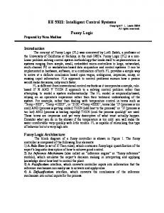
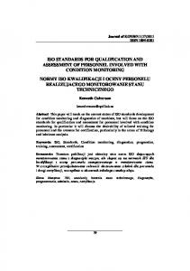
After the implementation, both controller systems were tested for various initial states. A graphical user interface implemented in MATLAB was used to demonstrate the movement of the vehicle, path of the movement and the final position and orientation of the vehicle. Figure 10 shows the path of the motion of the vehicle using fuzzy logic controller where the starting coordinates of the rear end point of the trailer was (3.09, 21.6) considering the coordinates of the dock as (0,0) and the values of Φt and Φc were 66 and 80 respectively. Here the final position was observed as -0.34, 0.12 and the orientation as 90.79 degrees. These values represents that the final position had a deviation of 34 centimeters along the negative x direction and the variation of the final orientation from the expected angle is 0.79 degrees. In comparison to the dimensions of the truck and trailer vehicle this deviation of the position and the expected final orientation can be considered as a successful backing up situation controlled by the designed fuzzy logic control system. Table 3 and table 4 represent the results for some of the successful performances of the fuzzy logic control system and the artificial neural network control system respectively.
xt 2.27 -3.41 -2.27 6.25 2.84 -6.25 6.30 3.98 6.82
Initial state yt Φt 20.45 76.55 24.43 95.17 18.75 126.21 19.89 74.48 18.18 82.76 19.32 138.62 18.19 68.28 19.89 62.07 19.32 68.28
Φc 63.41 73.64 143.18 74.48 82.76 138.62 68.28 62.07 68.28
Final state xt yt Φt 0.19 0.13 93.31 -0.42 0.1 90.84 -0.16 0.19 90.31 -0.73 0.13 83.34 -0.29 0.14 84.02 -0.61 0.18 91.28 -0.72 0.11 87.69 0.01 0.12 90.94 -0.77 0.11 91.61
In addition, the graphs were plotted to visualize the variations of the straight line distance from the dock to the rear end point of the trailer, distance from the dock to the rear end point along the x direction and the variation of the orientation of the trailer over the time. According to the figure 11 the graph on top shows the variation of the straight line distance from the dock to the rear end point of the trailer within the time period that the vehicle had been moving backward while the graphs on bottom right and bottom left shows the variation of the distance along x direction and the variation of the orientation of the truck with in the same time period respectively.
Initial position and orientation of the vehicle
Path of the motion Final position and orientation of the vehicle
Position of the dock
Figure 10. Simulation of the truck and trailer Table 3. Successful results of fuzzy logic controller xt 3.0 2.84 -2.27 -12.5 -5.11 13.64 -5.68 16.48
Initial state yt Φt 30.0 65.0 34.66 105.52 25.0 90.0 26.14 186.21 21.02 115.86 35.8 235.86 54.55 103.45 32.39 227.59
Φc 45.0 135.0 90.0 186.21 98.18 267.95 94.09 198.41
Final state xt yt Φt -0.37 0.19 89.16 -0.64 0.17 86.03 -0.46 0.16 92.77 -0.32 0.10 88.91 -0.52 0.19 91.13 -0.02 0.18 90.07 -0.24 0.12 90.65 -0.04 0.14 90.15
Figure 11. Variations of control variables Comparison of the two control systems. Since the neural network controller is designed in the range of a squired area of 20 meters of each side the comparisons were made only within this region. The graphs of the variations of the straight line distance from current position to the dock and the variations of distance along X direction and the variations of the orientation of the trailer with respect to time were used
376 Int. J Latest Trends Computing
Vol-2 No 3 September, 2011
to make the comparisons. Figure 12 shows the comparison of the movement controlled by the (a) fuzzy logic control system and (b) neural network control system. Both systems were tested from the same initial states with the values xt=2.27, yt=19.32, Φt=78.62, Φc=98.18.
(a) Fuzzy logic
(b) Artificial neural network
Figure 12. Comparison of the two controller systems From figure 12 it can be observed that the neural network controller allows a sharp turn of the trailer than that of the fuzzy logic controller. Also the figure 13 illustrates the graphs which represent the variations of the straight line distance from the dock to the rear end point of the trailer, variation of the distance alone positive X direction and the variation of the orientation of the trailer were compared. The dotted line of the graphs represents the variations of the variables when the neural network controller is used and the straight lines represent the variations of the same variables when fuzzy logic controller is used.
Figure 13. Comparison of the variation of control variables. In comparison of the fuzzy logic controller system and the neural network controller system of controlling
the backward motion of the truck and trailer vehicle into the loading dock, the fuzzy system could be developed in short period of time for a large range of starting positions than that of the neural network controller. The difficulty with the neural network controller is that there is finding the appropriate number of neurons in the hidden layer. Only possibility is to assign different configurations for the network and observe the performance of the training for the same data set. This is a much time consuming process and most of the time it reaches the local minima points stopping further training of the network. However in fuzzy controller all the possible configurations of the truck and the trailer has to be defined in the rule base where as the neural network controller has the ability of generalization so that it can produce correct output for some configurations which were not in the training data set. Furthermore, in the simulations performed under the constant velocity the motion of the vehicle guided by the neural network control system reaches the goal taking less time compared to the motion controlled by the fuzzy logic control system. But there is a higher variation of the orientation of the trailer when the neural network is used so that if the steering angle is made to be changed mechanically it must be capable of handling rapid changes of the angle.
5
Conclusion
The goal of this research was to design and develop a computer controller system to automate the backing up motion of a truck and trailer vehicle into the loading dock. Two controller systems were developed using fuzzy logic and a neural network respectively. The performances of the controls were compared using graphical representations of the control variables over the time. With the fuzzy logic controller system the truck and trailer can be controlled successfully to move into the loading dock from most of the selected starting configurations of the vehicle within a squire area of 100 meters of each side. And it is observed that when the distance along the Y direction is large at the starting point of the vehicle the final position and orientation of the vehicle is much closer to the expected values than that of starting from a position with small Y distance. Because of the length of the trailer it needs some space in Y direction to align with the desired final angle and the position when using both of these control systems. The neural network controller was trained to control the truck and trailer within a range of a squire area of 20 meters of each side with a data set of small variations from the desired final configurations of the truck and the trailer. Since it did not perform well in the training phase the output that can be achieved from neural network controller is less than that of the fuzzy logic controller system.
377 Int. J Latest Trends Computing
References [1] Derrick H. Nguyen, Bernard Widrow, “Neural Networks for Self-Leaning Control Systems”, IEEE Control systems magazine, April 1990. [2] Seong-Gon Kong, Bart Kosko, “Comparison of Fuzzy and Neural Truck Backer-Upper System”, IJCNN International Joint Conference on Neural Networks (Cat. No.90CH2879-5), Vol. 3, June 1990. [3] Seong-Gon Kong, Bart Kosko, “Adaptive Fuzzy Systems for Backing up a Truck-and-Trailer”, IEEE Transactions on neural networks, Vol. 3,No. 2, March 1992. [4] James A Freeman, “Fuzzy Systems for Control Applications: The Truck Backer-Upper”, The Mathematical Journal Miller Freeman Publications,
Vol-2 No 3 September, 2011
Vol. 4, Issue 1, 1994. [5] Graham J. Eatherley, Emil M Petriu, “A Fuzzy Controller For Vehicle Rendezvous and Docking”, IEEE Transactions on instrumentation and measurement, Vol. 44, No. 3, June 1995. [6] Andri Riid, Ennu Rustern, “Fuzzy Logic in Control: Truck Backer-Upper Problem Revisited”, scientific literature digital library and search engine, 2001. http://www.dcc.ttu.ee/andri/teosed/tbu.pdf. [7] Domen Novak, Dejan Dovžan, Simon Oblak, entitled "Automated Parking System For A Truck And Trailer", International Cultural and Academic Meeting of Engineering Students (ICAMES), 2007 http://msc.fe.unilj.si/icames/07/Automated_Parking_ System_For_A_Truck_And_Trailer.pdf