Abstract: owing to increase in variety of demands in industries, brushless dc (bldc) motor has achieved centre stage in all kinds of demands. This paper presents ...
www.ijraset.com IC Value: 45.98
Volume 5 Issue VI, June 2017 ISSN: 2321-9653
International Journal for Research in Applied Science & Engineering Technology (IJRASET)
Fuzzy Logic Based Controllers for Speed Control of BLDC Motor Ajai Kumar Singh1, Ankit Chhaba2, Ajay Chhillar3, Ashish Ranga 4, Rahul Dahiya5 1, 2
, 3, 4,5Department of Electrical Engineering, Deenbandhu Chhotu Ram University of Science and Technology Murthal, Sonepat (Haryana) India.
Abstract: owing to increase in variety of demands in industries, brushless dc (bldc) motor has achieved centre stage in all kinds of demands. This paper presents the application of state-of-the-art controllers to bldc motors for overall improvement in performance. The improvement in torque-speed characteristics at load and at no load is of utmost importance in industrial setups. The improvement in performance of the motor can be achieved by optimizing the motor design. Also it can be realized by implementing the advanced control strategies. To achieve the desired level of performance, the motor requires suitable speed controllers. In view of the fuzzy logic merits, this paper presents the design and implementation of tsk type flc, type-2 flc and pid controller with fuzzy compensation for the speed control of bldc motor. The control techniques applied have been evaluated in terms of various performance criteria and a comparative analysis has been carried out. The control and simulation had been performed in matlab simulink©. The comparative study of responses of tsk flc, type-2 flc and pid controller with fuzzy compensation shows that type-2 flc is better than other controllers. Keywords: bldc motor, pid controller, compensation, tsk-flc, type-2 flc, fou A. List Of Symbols u(t) Kp Ki Kd e(t) wi zi V ia, ib, ic ea, eb, ec R L M Kb Tem J D Ω Kt
Control action of PID controller Proportional gain Integral gain Derivative gain Error Firing strength of fuzzy rule Output level of a fuzzy rule Applied voltage Motor phase currents Motor phase back emfs Resistance Self inductance Mutual inductance Back emf constant Electromagnetic torque Moment of inertia Damping constant Angular speed Torque constant
I. INTRODUCTION A brushless dc motor is a kind of synchronous motor which are powered by DC electric current source and they are also known as electronically commutated motor (ECMs) with rotor position feedback. The phenomena utilized for controlling a brushless motors is done by using a three phase power semiconductor bridge. For providing proper commutation sequence to turn on the power
985 ©IJRASET: All Rights are Reserved
www.ijraset.com IC Value: 45.98
Volume 5 Issue VI, June 2017 ISSN: 2321-9653
International Journal for Research in Applied Science & Engineering Technology (IJRASET) devices in the inverter bridge the motor requires a rotor position sensor used for starting the motor. Based on the rotor position, the power devices are commutated sequentially every 60 degrees [1-3]. Instead of commutating the armature current using brushes, electronic commutation is used and for this reason, it is an electronic motor. This eliminates the problems associated with the brush and the commutators arrangement, for example, sparking and wearing out of the commutators brush arrangement, thereby, making a BLDC more rugged as compared to a dc motor. BLDC motors adopt Hall Effect sensors in place of mechanical commutators and brushes. The stators of BLDC motors are the coils and the rotors are the permanent magnets. The rotor rotates owing to the magnetic field generated by the stator. The position of the rotor is detected by the Hall Effect sensors as the commutating signals. BLDC motors, therefore, use permanent magnets instead of coils in the armature and hence, do not require brushes. Keeping in mind the various applications of BLDC motor, it is important to design low cost and efficient speed controller. Many techniques for BLDC motor speed control have been developed such as PID, Fuzzy logic controller, adaptive fuzzy logic controller. Gwo-Ruey Yu and Rey-Chue Hwang, in 2004, presented an optimal PID control design [4]. LQR technique was utilized to search the optimal parameters of the controller. This new PID tuning algorithm was applied to speed control of brushless dc motor. The results obtained using computer simulations were better than that obtained using traditional PID controller. R. Kandiban and R. Arulmozhiyal in [5] proposed an improved adaptive Fuzzy PID controller for speed control of brushless dc motor, in international conference on modeling, optimization and computing in 2012. Conventional PID controller is difficult to tune to obtain optimal parameters. Adaptive Fuzzy, on the other hand, is easy to use. A comparison of Adaptive Fuzzy PID with Fuzzy PID and conventional PID controllers showed it to be a better controller for speed control of BLDC motor. Although conventional PID controller is generally used for many control problems because it is easy to implement and have simple structure. However, in practice, conventionally tuned PID controllers do not give optimum performance. So, Genetic algorithm was proposed as a global optimizer by Prof. S. Srikanth and Mr. G. Raghu Chandra in 2012 [6]. The efficiency of this method was compared with that of the traditional methods. Simulation results showed that PID control tuned by GA provides more efficient closed loop response. Conventional PID controller does not guarantee rapidity and good dynamic and static performance of BLDCM. Wang Yuanxi, Yu Yali, Zhang Guosheng and Sheng Xiaoliang, in 2012, combined PID control with Fuzzy control to design Fuzzy auto-adjust PID controller that was fit for multivariable strong coupling nonlinear characteristics of BLDCM system [7]. Simulation experiments were performed in MATLAB/Simulink©. Computer simulation showed that as compared with the conventional PID controller, Fuzzy auto-adjust PID controller provides better dynamic and static performance. In 2013, H.E.A. Ibrahim, F.N. Hassan and Anas O. Shomer in [8] presented a Particle Swarm Optimization (PSO) technique and Bacterial foraging (BF) technique for determining the optimal parameters of PID controller for speed control of a brushless dc motor. The proposed techniques were more efficient in improving the step response characteristics as well as reducing the steady state error, rise time, settling time and maximum overshoot. Moreover, results showed that PSO technique was more efficient than BF technique. Pooja Sharma and Rajeev Gupta, in 2014, proposed another technique for optimum tuning of PID controller [9]. A newly developed algorithm named teaching learning base optimization algorithm was applied to search for optimal gains of PID controller. This algorithm is inspired by the teaching learning process and it works on the effect of influence of a teacher on the output of the learners in a class. It is a population based method. The results of computer simulations showed that TLBO is a better technique to tune PID controller for speed control of a BLDC motor. The results obtained using TLBO techniques were better than that obtained using LQR and PSO techniques. The various techniques discussed above gave good response for speed control of BLDC motor. But the responses obtained were oscillatory. To remove oscillations and achieve a better performance, some new techniques were required. So, this report presents the implementation of Sugeno type fuzzy logic controller (TSK FLC), PID controller with fuzzy compensation and Type-2 fuzzy logic controller for speed control of BLDC motor. II. METHODOLOGY A. PID controller with Fuzzy compensation A PID is control loop feedback mechanism used in industrial control system. In industrial process, the function of a PID controller is to correct the error between a measured process variable and desired reference value by calculating error and then generating corrective action that can minimize the error. The PID controller’s output calculation occurs in three separate modes – the proportional mode, integral mode and the derivative mode. The proportional mode accounts for the present values of the error, the integral mode accounts for past values of the error and the derivative action accounts for possible future values of the error, based on its current rate of change. The weighted sum of the three modes outputs is given as corrective action to the control element. PID controller is widely used in industries due to its ease of design and simple structure. PID control algorithm can be implemented as
986 ©IJRASET: All Rights are Reserved
www.ijraset.com IC Value: 45.98
Volume 5 Issue VI, June 2017 ISSN: 2321-9653
International Journal for Research in Applied Science & Engineering Technology (IJRASET) [10-11]: ( )=
. ( )+
.
( )
+
.
( )
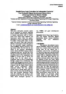
Conventional proportional-integral-derivative (PID) controllers, however, may not perform well for the complex processes, such as the high-order and time delay systems, nonlinear systems, complex and vague systems without precise mathematical models, and systems with uncertainties. Therefore, for such applications, compensation may be required for the PID controller to give better results [12-13]. Fuzzy plus PID controller has two nonlinear terms. One plays as an equivalent control and the other acts as a switching control. Fig.1 describes the basic block for PID controller with fuzzy compensation. It basically consists of a PID controller with Fuzzy logic controller in feedback. The reference value and the output of the process serve as the inputs to the FLC. The output of this FLC is added to the reference value set by the user and both, in combination, serves as the new reference for the PID controller. The error between this reference value and the actual output of the process serves as the input for the PID controller to control the process.
Fig.1 Block diagram of a PID controller with fuzzy
compensation
B. TSK Fuzzy Logic controller Fuzzy logic has rapidly become one of the most successful of today’s technology for developing sophisticated control system. In the past few years, the number and variety of applications of fuzzy logic control has grown rapidly [14]. The application area ranges from consumer products such as cameras, camcorder, washing machines and microwave ovens to industrial process control, medical instrumentation, and decision support system. Many decision-making and problem solving tasks are too complex to be understood quantitatively. However, people succeed by using imprecise knowledge. Fuzzy logic is all about the relative importance of precision. Fuzzy logic has two different meanings. In a narrow sense, fuzzy logic is a logical system which is an extension of multi valued logic. But, in wider sense, fuzzy logic is synonymous with the theory of fuzzy sets. Fuzzy logic expresses operational laws in linguistics terms instead of mathematical equations [15]. Many systems are too complex that they cannot be modeled accurately, even using complex mathematical equations; therefore traditional methods become inappropriate in these systems. However, the linguistic terms used in Fuzzy logic provide a feasible method for defining the operational characteristics of such systems. Fuzzy logic controller can be considered as a special class of symbolic controller. The configuration of fuzzy logic controller block diagram is shown in Fig.2.
Fig.2 Structure of a Fuzzy Logic Controller
987 ©IJRASET: All Rights are Reserved
www.ijraset.com IC Value: 45.98
Volume 5 Issue VI, June 2017 ISSN: 2321-9653
International Journal for Research in Applied Science & Engineering Technology (IJRASET) The fuzzy logic controller works in three main steps: Fuzzification, Fuzzy inference and Defuzzification Fuzzification may be defined as the process of mapping multiple measured crisp inputs into fuzzy membership functions. These fuzzy membership functions serve the purpose of inputs for FLC. These inputs are then mapped to output using fuzzy logic. This process is known as fuzzy inference. The mapping then provides a basis from which decisions can be made, or patterns discerned. There are two types of fuzzy inference systems that can be implemented in the Fuzzy Logic: Mamdani-type and Sugeno-type. These two types of inference systems differ in the way outputs are determined. The inference mechanism gives fuzzy output variables as its output. However, for the actual system to use this output, it must be in the form of crisp values. So, the fuzzy logic controller must convert its internal fuzzy output variables into crisp values. This conversion is called defuzzification. Takagi-Sugeno-Kang, or simply Sugeno type fuzzy logic controller, introduced in 1985, is very much similar to Mamdani type FLC in many respects [16]. The fuzzification part and the application of fuzzy operators are the processes that are similar in both types of FLCs. The main difference that exists between the two is the output membership functions. Whereas Mamdani type FLCs have a variety of choices for output membership functions, Sugeno type FLCs can only have either linear or constant membership functions. In Mamdani FLC, a rule is in the form: If input 1 is x and input 2 is y then output is z However, in sugeno type flc, the rules are of the form [17]: If input1 = x and input2 = y then output is z = ax + by + c For a zero order sugeno model, a = b = 0, and hence output level is constant. The basic block diagram of a TSK-FLC is as shown in fig.3 below.
Fig.3 Basic structure of a TSK-FLC A Sugeno rule operates as shown in the fig.4.
Fig.4 Operation of a Sugeno type FLC
988 ©IJRASET: All Rights are Reserved
www.ijraset.com IC Value: 45.98
Volume 5 Issue VI, June 2017 ISSN: 2321-9653
International Journal for Research in Applied Science & Engineering Technology (IJRASET) Each rule weights its output level, zi, by the firing strength of the rule, wi. The firing strength, for example, for an AND rule taking input1 = x and input2 = y is given by wi = ANDMETHOD(F1(x),F2(y)) where F1,2(.) are the corresponding membership functions for inputs 1 & 2. The final output of the system is computed to be as ∑ wizi Final Output = ∑ wi this is the weighted output of all rule outputs, where N is the number of rules.
C. Type-2 Fuzzy logic controller Type-2 fuzzy logic systems, due to their ability to model uncertainty, have recently been utilized in many control processes. With the development of T2 FLSs and their ability to handle uncertainty, utilizing type-2 FLCs has attracted a lot of interest in recent years. The concept of type-2 fuzzy sets was first introduced by Zadeh as an extension of the concept of well-known ordinary fuzzy sets, type-1 fuzzy sets [18-19]. A type-2 fuzzy set is characterized by a fuzzy membership function i.e. the membership grade for each element is also a fuzzy set in [0,1], unlike a type-1 fuzzy set ,where the membership grade is a crisp number in [0,1].The membership functions of type-2 fuzzy sets are three dimensional and include a footprint of Uncertainty(FOU), which is the new third dimension of type-2 fuzzy sets [20-21]. The footprint of uncertainty provides an additional degree of freedom to handle uncertainties. T2 FLSs are characterized by the shape of their MFs. The membership function of general type-2 fuzzy is shown in fig.5. The extra mathematical dimension is provided by the blurred area. The FOU is bounded by upper and lower MFs.
Fig.5 General membership function for type-2 FLC The structure of a type-2 FLS is shown in fig.6. This structure is very similar to the type-1 fuzzy systems [22].
Fig.6 Structure of a type 2 FLC
989 ©IJRASET: All Rights are Reserved
www.ijraset.com IC Value: 45.98
Volume 5 Issue VI, June 2017 ISSN: 2321-9653
International Journal for Research in Applied Science & Engineering Technology (IJRASET) The only difference between type-1 and type-2 fuzzy logic system structure is in the block "type-reducer”. In a type-1 FLS, the output of the inference engine is normally a type-1 fuzzy set but, in a type-2 FLS, the output of the inference engine is normally a type-2 fuzzy set. Hence, using a type-reducer block, a type-1 fuzzy set is obtained from the type-2 output sets of the FLS. This operation is called type reduction [23]. III. MATHEMATICAL MODELLING OF BLDC MOTOR The BLDC motor has three stator windings and a permanent magnet on the rotor. Rotor induced currents can be neglected due to the high resistivity of both magnets and stainless steel. The voltage equations of BLDC motor can be given as [23-24]: =
+
+ =
=
+
+ +
+
+
+
(1)
+
+
+
(2)
+
(3)
Where ea, eb and ec are the back emfs which are functions of rotor angle given by = (4) where Kb is the back emf constant. From the above equations, the following matrix can be deduced: 0 + 0 0
=
0 0
+
(5)
0
Since there is no saliency, self inductance is independent of the rotor position. Therefore, =
=
=
(6)
And mutual inductances =
=
=
=
=
=
(7)
For a balanced three phase system, phase resistances are equal, i.e., =
=
=
(8)
Rearranging equations 5, we get 0 =
+ 0 0
0 0
+
(9)
0
Electromagnetic torque can be expressed as: = .
+
+
(10)
Electromagnetic torque depends upon back emf and rotor current and can be expressed as: =
[
(11)
]
From the above equations, the transfer function can be deduced to be as follows: ( )=
( ) ( )
= [(
)(
)
]
(12)
990 ©IJRASET: All Rights are Reserved
www.ijraset.com IC Value: 45.98
Volume 5 Issue VI, June 2017 ISSN: 2321-9653
International Journal for Research in Applied Science & Engineering Technology (IJRASET) IV. PERFORMANCE ANALYSIS AND RESULTS A. BLDC motor Simulink model The speed control of the motor has been achieved by using PID controller with fuzzy compensation, TSK Fuzzy logic controller and Type-2 fuzzy logic controller. All the experiments have been performed in MATLAB/Simulink©. First of all, a model of the BLDC motor was developed from its transfer function as shown in fig.7.
Fig.7 Block diagram of a BLDC motor The following values of the parameters have been used as assumed by Gwo-Ruey Yu and Rey-Chue Hwang in []: L = 0.052 H R = 21.2 Ω J = 1 * 10-5 Kg-m s2/rad D = 1 * 10-4 Kg-m s/rad Kt = 0.1433 Kg-m/A Kb = 0.1433 Vs/rad Substituting these values in the above model, the simulink diagram for BLDC motor at no load can be obtained as shown in fig.8
Fig.8 Simulink diagram of BLDC motor at no-load Fig.9 shows simulink model of BLDC motor at load.
Fig.9 Simulink diagram of BLDC motor at no-load
991 ©IJRASET: All Rights are Reserved
www.ijraset.com IC Value: 45.98
Volume 5 Issue VI, June 2017 ISSN: 2321-9653
International Journal for Research in Applied Science & Engineering Technology (IJRASET) B. Speed control of BLDC motor using PID controller with fuzzy compensation To achieve a better speed control than PID controller, compensation, in addition to the controller, is used. In present case, fuzzy compensation is used with PID controller. The simulink diagram is shown in fig.10 where Fuzzy logic controller is used in feedback and acts as compensator. The reference speed and the actual speed output are used as the two inputs for fuzzy logic controller. The membership functions for input variables have been shown in fig. 11 (a) and (b). Five triangular membership functions have been used for both the inputs and nine triangular membership functions have been used for output of the fuzzy logic controller. Membership functions for output are shown in fig.11 (c). The rules are as shown in table 1.
Fig. 10 Simulation diagram of speed control of BLDC motor using PID controller with fuzzy compensation
(a)
(b)
992 ©IJRASET: All Rights are Reserved
www.ijraset.com IC Value: 45.98
Volume 5 Issue VI, June 2017 ISSN: 2321-9653
International Journal for Research in Applied Science & Engineering Technology (IJRASET)
(c) Fig 11 Membership functions for (a) input variable error, (b) input variable rate of change of error and (c) output variable control action Table 1 Rule table for Fuzzy logic controller e/de
NM
NS
ZE
PS
PM
NM
NVL
NL
NM
NS
ZE
NS
NL
NM
NS
ZE
PS
ZE
NM
NS
ZE
PS
PM
PS
NS
ZE
PS
PM
PL
PM
ZE
PS
PM
PL
PVL
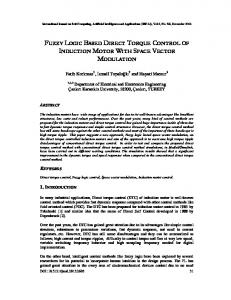
The speed response of BLDC motor was obtained as shown in fig.12. Assuming the tolerance band to be ±5% of the reference value, the following values of time response specifications were obtained: Settling time, ts = 0.0079 sec Rise time, tr = 0.0018 sec Peak overshoot, Mp = 64% Steady state error, ess = 0.4%
Fig.12 Speed response of BLDC motor (at no load) using PID controller with fuzzy compensation Fig.13 shows Torque-Speed characteristics. As is clear from the curve, initially, torque increases and speed also increases. When the speed is just at the verge of reaching the desired value, which is 1000 rpm here, torque becomes constant. Due to the oscillations in the response, the speed crosses the reference value and hence torque becomes negative so as to make the speed reach the desired
993 ©IJRASET: All Rights are Reserved
www.ijraset.com IC Value: 45.98
Volume 5 Issue VI, June 2017 ISSN: 2321-9653
International Journal for Research in Applied Science & Engineering Technology (IJRASET) value. Due to persistent oscillations, the torque increases and decreases consistently till the speed become constant and torque becomes zero.
Fig.13 Torque-Speed characteristics
Fig.14 Speed response of BLDC motor (at load) using PID controller with fuzzy compensation The speed response for BLDC motor at load using PID controller with fuzzy compensation is shown in fig. 14. The response shows that the speed for motor at load did not reach the reference value but settled at 590 rpm. C. Speed control of BLDC motor using Sugeno type Fuzzy logic controller (TSK FLC) Sugeno type Fuzzy logic controller has been implemented for speed control of BLDC motor in MATLAB/Simulink©. The simulink diagram is shown in fig. 15. The error and the rate of change of error have been used as the inputs to the fuzzy controller. The inputs are first scaled using scaling factors and then fed to the controller for further processing. The output is again scaled to give the desired response. Input membership functions are shown in fig. 16(a) and (b). Triangular membership functions have been used for both the inputs. Output membership functions are chosen to be linear as shown in fig. 16 (c). The rule base consists of 25 rules. These rules are depicted in table 2.
Fig. 15 Simulink diagram of speed control of BLDC motor using TSK-FLC
994 ©IJRASET: All Rights are Reserved
www.ijraset.com IC Value: 45.98
Volume 5 Issue VI, June 2017 ISSN: 2321-9653
International Journal for Research in Applied Science & Engineering Technology (IJRASET)
(a)
(b)
(c) Fig. 16 Membership functions for (a) Input variable “error”, (b) Input variable “rate of change of error”, and (c) Output variable “control action” Table 2 Rule table for TSK-FLC e/de
NM
NS
ZE
PS
PM
NM
NVL
NL
NM
NS
ZE
NS
NL
NM
NS
ZE
PS
ZE
NM
NS
ZE
PS
PM
PS
NS
ZE
PS
PM
PL
PM
ZE
PS
PM
PL
PVL
The speed response of TSK fuzzy logic controller for speed control of BLDC motor is shown in fig. 17.
995 ©IJRASET: All Rights are Reserved
www.ijraset.com IC Value: 45.98
Volume 5 Issue VI, June 2017 ISSN: 2321-9653
International Journal for Research in Applied Science & Engineering Technology (IJRASET)
Fig. 17 Speed response of BLDC motor (at no load) using TSK-FLC The speed rises almost linearly with time and reaches the desired value smoothly. The following values of time response specifications are observed: Settling time, ts = 0.042 sec Rise time, tr = 0.06 sec Peak overshoot, Mp = 0% Steady state error, ess = 0% Fig.18 represents Torque-Speed characteristics. Since the response shows no oscillations, the characteristic curve does not come out to be concentric circles near the end as is the case for the controllers studied till now. The torque first increases and then decreases. When speed becomes constant, torque becomes zero. Fig. 19 shows the response of TSK-FLC for speed control of BLDC motor according to which the speed reached up to 795 rpm and became constant thereafter.
Fig. 18 Torque-Speed Characteristics
Fig. 19 Speed response of BLDC motor (at load) using TSK-FLC
996 ©IJRASET: All Rights are Reserved
www.ijraset.com IC Value: 45.98
Volume 5 Issue VI, June 2017 ISSN: 2321-9653
International Journal for Research in Applied Science & Engineering Technology (IJRASET) D. Speed control of BLDC motor using Type-2 Fuzzy logic controller The response of TSK FLC has been observed to be very good. But Type-2 FLC was used to achieve a better performance. The simulink block diagram for speed control of BLDC motor using type-2 FLC is shown in fig. 20. It consists of a step input, which generates a reference speed of 1000 rpm. Two FLC blocks have been used. One FLC block has inner membership functions and the other has outer membership functions. The results of both blocks are combined and their average is used as the final output.
Fig. 20 Simulink diagram of speed control of BLDC motor using Type-2 FLC The input membership functions for first FLC block is as shown in fig. 21 (a) and (b). Error and rate of change of error have been chosen as the input variables. Three triangular shaped membership functions have been used for each of the input variables. Fig. 22 (a) and (b) shows membership functions for input variables for second FLC block. Output membership functions have been shown in fig. 23 The rules are as shown in table 3
(a)
(b) Fig 21 Inner membership functions for (a) Input variable “error” and (b) Input variable “rate of change of error”
997 ©IJRASET: All Rights are Reserved
www.ijraset.com IC Value: 45.98
Volume 5 Issue VI, June 2017 ISSN: 2321-9653
International Journal for Research in Applied Science & Engineering Technology (IJRASET)
(a)
(b) Fig. 22 Outer membership functions for (a) input variable “error” and (b) input variable “rate of change of error”
Fig. 23 Membership functions for output variable “control action” The response of type-2 FLC is as shown in fig. 24. According to this plot, the following values of time response specifications can be inferred: Settling time, ts = 0.0028 sec Rise time, tr = 0.003 sec Peak overshoot, Mp = 30% Steady state error, ess = 0% Table 3 Rule table for Type-2 FLC e/de
NS
ZE
PS
NS
NM
NS
ZE
ZE
NS
ZE
PS
PS
ZE
PS
PM
998 ©IJRASET: All Rights are Reserved
www.ijraset.com IC Value: 45.98
Volume 5 Issue VI, June 2017 ISSN: 2321-9653
International Journal for Research in Applied Science & Engineering Technology (IJRASET) The Torque-Speed characteristics are shown in fig. 25.
Fig. 24 Speed response of BLDC motor (at no load) using Type-2 FLC
Fig. 25 Torque –Speed characteristics The above values indicate that Type-2 fuzzy logic controller gave best results for speed control of BLDC motor. Type 2 FLC was also implemented for speed control of BLDC motor at load. The response was obtained as shown in fig. 26.
Fig. 26 Speed response of BLDC motor (at load) using Type-2 FLC
999 ©IJRASET: All Rights are Reserved
www.ijraset.com IC Value: 45.98
Volume 5 Issue VI, June 2017 ISSN: 2321-9653
International Journal for Research in Applied Science & Engineering Technology (IJRASET) The speed reached 880 rpm in just 0.0025 seconds which is the best response obtained till now. A tabular quantitative comparison of the above responses is shown in table 4. As is clear from the table, 1) Settling time is best for type-2 Fuzzy logic controller, which is 0.0028 seconds 2) Rise time is minimum for PID controller which is 0.002 sec next to 0.003 sec for type-2 FLC. 3) TSK FLC give no overshoot whereas type-2 FLC gives a peak of 30% and PID and PID with fuzzy compensation give a much larger overshoot 4) Steady state error is zero for TSK FLC and type 2 FLC whereas it is 0.6 % for PID controller and 0.4 % for PID controller with fuzzy compensation. Table 4 Comparison of controllers in terms of time response specifications (For motor at no load) LQRPID with fuzzy TSKType-2 PID compensation FLC FLC Settling time, ts (in sec) Rise time, tr (in sec)
0.008
0.0079
0.042
0.0028
0.002
0.018
0.12
0.003
Peak overshoot, Mp
65 %
64%
0%
30%
Steady state error, ess
0.6%
0.4%
0%
0%
Another comparison is shown in table 5. Whereas table 4 shows comparison on the basis of time response specifications, table 5 shows comparison on the basis of performance indices. Table 5 Comparison of controller in terms of performance characteristics (for motor at no load) LQRPID with fuzzy TSKType-2 PID compensation FLC FLC
ISE
760.9
750
8542
158.7
ITSE
-
-
63.46
0.026
IAE
6.6
4.7
0.03
0
From this table, it can be deduced that Type-2 FLC gives minimum value for all the three performance indices, i.e., Integral Square Error (ISE), Integral Time Square Error (ITSE) and Integral Absolute Error (IAE). The values of ITSE for PID and PID with fuzzy compensation are continuously varying with time. V. CONCLUSION A Type 2 fuzzy logic controller (FLC), Sugeno type fuzzy logic controller and PID controller with fuzzy compensation has been
1000 ©IJRASET: All Rights are Reserved
www.ijraset.com IC Value: 45.98
Volume 5 Issue VI, June 2017 ISSN: 2321-9653
International Journal for Research in Applied Science & Engineering Technology (IJRASET) employed for the speed control of Brushless DC motor and the analysis of results of the performance of these controllers are presented. The modeling and simulation of the complete drive system is described in this thesis. Effectiveness of the controllers is established by performance comparison of the controllers with PID controller with gains tuned using LQR technique. A performance comparison among the controllers has been carried out by simulation runs confirming the validity and superiority of type-2 fuzzy logic controller. The performance of the PMBLDC motor with reference to LQR-PID controller showed that type-2 FL controller improved the performance of PMBLDC motor (at load as well as at no load condition) much better than other controllers. REFERENCES [1] [2] [3] [4] [5] [6] [7] [8] [9] [10] [11] [12] [13] [14] [15] [16] [17] [18] [19] [20] [21] [22] [23] [24] [25]
Chang-liang Xia, “Permanent Magnet Brushless DC Motor Drives and Controls”, Wiley & Sons, Singapore, 2012. Kalavathi MS, Reddy CS (2012) Performance Evaluation of Classical and Fuzzy Logic Control Techniques for Brushless DC Motor Drive. IEEE International Power Modulator and High Voltage Conference: 488-491 Pillay P, Krishnan R (1991) Application characteristics of PM synchronous and brushless DC motors for servo drives. IEEE Transactions on Industry Applications 27(5): 986-996 Yu GR, Hwang RC (2004) Optimal PID speed control of Brushless DC motors using LQR approach. IEEE international conference on Systems, man and cybernetics: 473-478 Kandiban R, Arulmozhiyal R (2012) Speed control of BLDC motor using adaptive fuzzy PID controller. International conference on Modeling, Optimization and computing, Elsevier: 306-313 Srikanth S, Chandra GR (2012) Modeling and PID control of the Brushless DC motor with the help of Genetic algorithm. IEEE international conference on Advances in Engineering, Science and Management, Odalarevu, India: 639-644 Yuanxi W, Yali Y, Guosheng Z, Xiaoliang S (2012) Fuzzy Auto-adjust PID Controller Design of Brushless DC Motor. International conference on Medical Physics and Biomedical Engineering, Elsevier: 1533-1539 Ibrahim HEA, Hassan FN, Shomer AO (2014) Optimal PID control of a brushless DC motor using PSO and BF techniques. Ain Shams engineering journal, Elsevier 5(2): 391-398 Sharma P, Gupta R (2014) Tuning of PID controller for a linear BLDC motor using TLBO technique. Sixth international conference on Computational intelligence and Communication networks: 1224-1228 Ang K, Chong G Li Y (2005) PID control system analysis, design and technology. IEEE transactions on control system technology 13(4): 559-576 Zhang Z, Huo Z, Xiao Z (2002) PID control with fuzzy compensation for hydroelectric generating unit. Proceedings of IEEE International Conference on Power System Technology 4: 2348-2352 Xiao-Gang Duan, Hua Deng and Han-Xiong Li, " A Saturation-Based Tuning Method for Fuzzy PID Controller”, IEEE Transactions on Industrial Electronics, Vol. 60, No. 11, pp. 5177-5185, November 2013 N.Li, Design of a Hybrid Fuzzy Logic Proportional plus conventional Integral Derivative Controller”, IEEE Transactions on Industry Applications, Vol. 27, No. 4, pp. 449-463, November 1998. C. Lee, “Fuzzy logic in control systems : Fuzzy logic controller – Part 1” , IEEE Trans. On systems, man and cybernetics, vol. 20, no. 2, pp. 419-435, March 1990. C. Lee, “Fuzzy logic in control systems: Fuzzy logic controller – Part 2”, IEEE Trans. On systems, man and cybernetics, vol. 20, no. 2, pp. 419-435, March 1990. C.L. Tseng, S.Y. Wang, S.C. Chien and C.Y. Chang, " Development of a self-tuning TSK-Fuzzy speed control strategy for switched reluctance motor”, IEEE Transactions on Power Electronics, Vol. 27, No. 4, pp. 2141- 2152, April 2012. Jian-Xin Xu, Zhao-Qin Guo and Tong Heng Lee, “ Design and Implementation of a Takagi-Sugeno Type Fuzzy Logic Controller on a Two –Wheeled Mobile Robot”, IEEE Transactions on Industrial Electronics, Vol. 60, No. 12, pp. 5717-5728, 2013 Meena Tushir and Smriti Srivastava, "Type-2 fuzzy logic controller implementation for tracking control of DC motor”, International Journal of Computer Network and Security, Vol. 3, No.1, pp. 34-41, 2011. Tufan Kumbasar, “Robust Stability Analysis and Systematic Design of Single Input Interval Type-2 Fuzzy Logic Controllers”, IEEE Transactions on Fuzzy Systems, Vol. 24, No. 3, pp. 675-694, 2016. N.N. Karnik, Jerry M. Mendel and Q. Liang,” Type-2 Fuzzy Logic Systems”, IEEE Transactions on Fuzzy Systems, Vol. 7, No. 6, pp. 643-658, 1999. Saba T. Salim, “Design of type-2 fuzzy logic controller for a simple furnace system”, Eng. & Tech. Journal, Vol. 8, No. 8, pp. 1306-1318, 2012. Syed Mohamad Reza Haji Mirzaie, Hodeiseh Gordan, Jalil Shirazi and Amin Nikbakht, “Pitch aircraft control with type-2 FLC and PD controller”, Journal of Electrical and Electronic Engineering, Vol. 3, No. 2-1, pp. 12-15, 2015. Tzyy-Chyang Lu, “Genetic-algorithm-based type reduction algorithm for interval type-2 fuzzy logic controllers”, Engineering Applications of Artificial Intelligence, ScienceDirect, Vol. 42, pp. 36-44, June 2015. P. Pillay & R. Krishnan, “Modeling, Simulation and analysis of PM motor drives, part-1: the PM synchronous motor drive”, IEEE Transactions on Industry Applications, Vol. 25, No. 2, pp. 265-273, 1989 P. Pillay & R. Krishnan, “Modeling, Simulation and analysis of PM motor drives, part-2: the brushless DC motor drive”, IEEE Transactions on Industry Applications, Vol. 25, No. 2, pp. 274-279, 1989
1001 ©IJRASET: All Rights are Reserved