World Academy of Science, Engineering and Technology 53 2011
Fuzzy Logic Speed Controller with Reduced Rule Base for Dual PMSM Drives Jurifa Mat Lazi, Zulkifilie Ibrahim, Marizan Sulaiman, Fizatul Aini Patakor, Siti Noormiza Mat Isa Abstract—Dual motor drives fed by single inverter is purposely designed to reduced size and cost with respect to single motor drives fed by single inverter. Previous researches on dual motor drives only focus on the modulation and the averaging techniques. Only a few of them, study the performance of the drives based on different speed controller other than Proportional and Integrator (PI) controller. This paper presents a detailed comparative study on fuzzy rule-base in Fuzzy Logic speed Controller (FLC) for Dual Permanent Magnet Synchronous Motor (PMSM) drives. Two fuzzy speed controllers which are standard and simplified fuzzy speed controllers are designed and the results are compared and evaluated. The standard fuzzy controller consists of 49 rules while the proposed controller consists of 9 rules determined by selecting the most dominant rules only. Both designs are compared for wide range of speed and the robustness of both controllers over load disturbance changes is tested to demonstrate the effectiveness of the simplified/reduced rulebase. Keywords—Dual Motor Drives, Fuzzy Logic Speed Controller, Reduced Rule-Base, PMSM
have the same behavior [2] . On the other hand, a variation of load for both motors will create perturbations on the electrical part and perhaps a malfunctioning of the system. For this type of disturbance, a control drive is needed to compensate the disturbance in order to make the system back to its origin. After several reading, “mean and differential torque” [3],[4],[5],[6] technique is selected to overcome the loss of adhere of the motor, rather than conventional averaging technique that treat the dual motor as a single motor. II. FUZZY LOGIC CONTROLLER For widespread industrial applications, such as high performance motor drives, accurate motor speed control is required in which regardless of sudden load changes and parameter variations [7]. Hence, the control system must be design very carefully as it required to ensure the optimum speed operation under the environmental variations, load variations and structural perturbations. Alternative control strategies have been studied extensively in attempts to provide accurate control capability. Among many kinds of control schemes, fuzzy logic controller (FLC) is one of the superior schemes used for plants having difficulties in deriving mathematical models or having performance limitations with conventional linear control schemes [8] . Reference [7] also mentioned that the FL and neural network (NN) became a pleasing approach to high performance controllers for non linear systems and has been practical to electrical drives. The present paper presents a study of a DC motor with FL speed controller. Besides that, FLC is broadly used by numerous publications with diversity of industrial drive applications such as vector controlled induction motor [9],[10],[11], permanent magnet synchronous motor [12],[13], brushless DC motor [14] and switched reluctance motor [15],[16].Theoretically, FL is based on human reasoning, providing algorithms which can convert a set of linguistic rules based on expert knowledge into an automatic control strategy. There is no need of mathematical models to deal with a problem, but skill is needed to create the rules in a particular FL controller [17]. This point also being supported by [13] which stated that a fuzzy control algorithm embeds the intuition and experience of an operator designer and researcher as the concept of FLC is to utilize the qualitative knowledge of a system to design a practical controller.Dual PMSM drives are at first modeled in MATLAB/Simulink program. As mentioned before, the standard controller is designed based on the
I. INTRODUCTION
I
N many applications, one motor is controlled by one converter. These systems are called SMSC, Single Machine Single Converter system [1]. Multi Machine Systems (MMS) are more and more used for industry today. These systems allow to extend the field of high power applications or to increase their flexibility, mechanical simplicity and safety operating. However, it includes a lot of power switches which are large in size, costly and bulky. The high cost and large size of the inverter make such dual inverter, dual motor drive configurations economically less competitive. Therefore, the need for dual motor drives fed by single inverter is growing consequently to reduce size and cost with respect to the single motor drives, either in industrial or in traction application. But, the reduction number of power electronics switches and other components will results the paralleling of the drives systems. If the load torque for each motor is still the same, there is no speed changes will be encountered because every motor will J.M.Lazi is a PhD student in Faculty of Electrical Engineering, Unuversiti Teknikal Malaysia, Melaka. (e-mail:
[email protected]). Z. Ibrahim is with Faculty of Electrical Engineering, Universiti Teknikal Malaysia Melaka, Malaysia. (e-mail:
[email protected]). M. Sulaiman. is with Faculty of Electrical Engineering, Universiti Teknikal Malaysia Melaka. (e-mail:
[email protected]). F. A. Patakor is a PhD student in Faculty of Electrical Engineering, Unuversiti Teknikal Malaysia, Melaka (e-mail:
[email protected]) S.N.M.Isa is a MSc student in Faculty of Electrical Engineering, University Teknikal Malaysia, Melaka. (e-mail:
[email protected])
252
World Academy of Science, Engineering and Technology 53 2011
common criteria of fuzzy speed controller that have been reviewed from various publications. This means 49 rules is a standard approach for the FL speed control with PMSM drive application. Meanwhile, the proposed controller consists of 9 rules which are formed by minimizing the number of membership function used. In this case, three rules for speed error and three rules for change in speed error is used, so that 3x3 = 9 rules are produced. The same PMSM drive model is being used for standard 49 rules and simplified 9 rules, so that a fair comparison is enabled. It has to be noted that 49 rules are represented by ‘standard design’ and the proposed controller are represented by ‘case design’.The results from both controllers are being compared and evaluated to show the appropriateness and effectiveness of the proposed controller which aims to achieve the following properties: robustness around the variety of operating conditions and invariant dynamic performance in presence load disturbance while maintaining the performance obtained by ‘standard design’ controller.
actual phase currents (ia, ib, ic) are compared with reference phase current (ia*, ib*, ic*) using three independent comparator in hysteresis controller. The logic condition for six inverter switches is chosen by the output of the comparator [1].When the phase “a” current is smaller than (i*-Δi), where Δi is the hysteresis band, the output of the comparator is “1”, the “a” phase will be connected with the positive track of DC link. In contrast, if the phase “a” current is bigger than ( i*- Δi ), the output of the comparator will become “0”, and the “a” phase will connected to the negative track of DC bus. A similar procedure exists in the other legs. The reason that this is called a hysteresis controller is that the leg voltage switches to keep the phase current within the hysteresis band. The phase currents are, therefore, approximately sinusoidal in steady state. The smaller the hysteresis band, the more closely do the phase currents represent sine wave. Small hysteresis band, however, imply a high switching frequency, which is a practical limitation of the power device. Increased switching frequency also implies increased inverter losses. A. Mathematical model The simulated machines are smooth air gap PMSMs without any damping circuits in the rotor. The rotors field are constant and created by permanent magnets and the e.m.f are considered as sinusoidal. The simplified electric equations for motor “1” can be presented as below [3]:
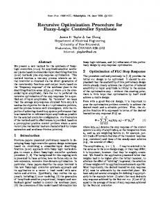
III. DUAL PMSM DRIVE SYSTEM The basic structure of the dual PMSM drives with hysteresis current control in the stationary reference frame and with Fuzzy Logic speed controller is shown in Fig.1. Three independent hysteresis current controllers in the three phase a,b,c reference frame are applied in this scheme. In high performance servo drives, hysteresis current controllers are used to ensure that the actual currents flowing into the motor are as close as possible to the current references.
v1 = Ri1 + L
di1 + jpω r ,1ψ r ,1 dt
T1 − TL ,1 = J ω1
∗
i q ,1
id ,1
ω2
∗
id ,2
i a ,b ,c
abc
i1( a ,b , c )
iq , 2
∗
dt 3 with T1 = pℑm{i1ψ r ,1 } 2 dθ ω r ,1 = 1 dt
∗ DQ
ω1
∗
∗
abc
ω2 Fig. 1 Hysteresis Current Control for Dual PMSM configuration
1 HCCa
2
ia
2
i b*
HCCb
3
ib
3
i c*
HCCc
(3)
ωr : Motor Angular velocity, Ψr : Rotor flux,
i2 ( a ,b ,c )
1
(2)
Where;
DQ
i a*
dω r ,1
(1)
ic
4 i c,act 5 i b,act 6 i a,act
Fig.2 Hysteresis Current Control
T : Electrical torque, TL : Load torque, J : Moment of Inertia. θ : Instantaneous angular position The model of the motor “2” can be derived from (1) to (3) by changing the subscript “1” to “2”. With the assumptions, motor “1” and motor “2” are equal in all parameters but have different loads. The space vectors of the rotor fluxes, ψr,1 and ψr,2 are equal in magnitude and its instantaneous position θ1 and θ2 respectively in the stationary frame. Consider a rotating reference frame d,q whose direct axis “d” is along the direction of (ψr,1+ψr,2)/2 and its instantaneous angular position is θ=(θ1+θ2)/2. Based on this reference, the electromagnetic torque of the motors “1” and “2” can be expressed as:
T1 =
Fig.2. shows the block diagram for hysteresis controller in order to produce the output signal. The
253
3 p.ψ r ,1 .iq ,1 2
(4)
World Academy of Science, Engineering and Technology 53 2011
T2 =
3 pψ r , 2 .iq , 2 2
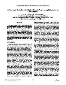
factors play a vital role for the FLC which effect the stability, oscillations and damping of the system, hence needs to be chosen with utmost care [11]. The factors Ge and Gce are chosen to normalize the speed error and the change in speed error respectively. The factor Gcu is so chosen that one can get the rated current for rated conditions. Fine tuning to the specification is achieved by trial and error. Therefore, the constants are taken as Ge = 0.0003, Gce = 4 and Gcu = 3 in order to get optimum drive performances. For the next step, the membership functions of e, ce and cu are determined which perform important tasks of the FLC and being main focused in this paper. Two different fuzzy sets are designed as shown in Fig. 4 and Fig. 5 respectively. The shape of the fuzzy sets on the two extreme ends of the universe of discourse is taken as trapezoidal whereas all other intermediate fuzzy sets are triangular with overlap to each other as standard approach. The width of triangular membership function is divided equally in a range (Universe of Discourse) with overlap to each other.
(5)
And the average “Σ” and differential “Δ” of the current and torque and torque are as follows:
i1 + i2 2 T + T2 T∑ = 1 2 i∑ =
i1 − i2 2 T − T2 : TΔ = 1 2 ;
iΔ =
(6) (7)
The FLC, as illustrated in Fig. 3, is a standard structure with inputs of speed error, e and change in speed error, ce and output is change in q-axis reference current, ∆iqs* The triangular membership function is used and the input and output scaling factors are determined. By referring to Fig. 3b, the FLC executes the rule base taking the fuzzy variables e and ce as the inputs and quantity of ∆iqs* as the output are processed in the defuzzification unit.
(a)
(b)
Fig. 3 (a) Fuzzy Logic Controller (b) Internal Structure of FLC TABLE I PMSM TEST MOTOR
No 1 2 3 4 5 6 7
Motor Specifications Rated Torque Rated Speed Inertia Resistance Inductance Magnet Flux DC link Voltage
Value 8 Nm 209 rad/s 0.0006329 kgm2 Fig. 4 Membership functions of ‘standard design’ for speed error, change in speed error and q-axis command current
0.9585 Ω 0.00525 H 0.1827 Vs 300
The fuzzy rule-base matrix for ‘standard design’ and ‘case design’ are shown in Table II and Table III respectively. As declared previously, the rules of the ‘standard design’ are determined by common criteria from many publications while the rules of the ‘case design’ parameters are determined by standard approach with reducing the number of fuzzy rule-base. The linguistic elements used are the same as those used in most publications [9],[17] . Fixed-step mode is selected for the computational time interval. Numerical method for solving differential equations is Dormand-Prince and Mamdani-type fuzzy inference is used [11]. The values of constants, membership functions and fuzzy sets for input/output variables in this study are selected by trial and error to obtain the optimum drive performance.
B. Design of Fuzzy Logic Controller The main goal of the control system is to determine the effectiveness of the ‘case design’ for high performance PMSM drive by comparing the speed response with ‘standard design’ obtained.The ‘standard design’ is designed first, on the basis of the speed response to the step rated speed command (209 rad/s) under no-load conditions with rated inertia. The design criteria are set in terms of a speed overshoot less than 0.1 rad/s and minimum rise time considering the limited current capability of the inverter. The scaling factors, Ge, Gce and Gcu are chosen for fuzzification, as well as for obtaining the actual output of the command current. These scaling
254
World Academy of Science, Engineering and Technology 53 2011
IV. RESULTS (a) 300 200
speed(s)
100 0 -100 speed reference
-200
speed m2 speed m1
-300 0
0.2
0.4
0.6
0.8
1
time(s)
(b) 300
speed(rad/s)
200 100 0 -100 speed reference
-200
Fig. 5 Membership functions of ‘case design’ for speed error, change in speed error and q-axis command current
speed m1
-300 0
Change in speed error, ce
NL
NM
NS
ZE
PS
PM
PL
NL
NL
NL
NL
NL
NM
NS
ZE
NM
NL
NL
NL
NM
NS
ZE
PS
NS
NL
NL
NM
NS
ZE
PS
PM
ZE
NL
NM
NS
ZE
PS
PM
PL
PS
NM
NS
ZE
PS
PM
PL
PL
PM
NS
ZE
PS
PM
PL
PL
PL
300
PL
ZE
PS
PM
PL
PL
PL
PL
200
speed error, ce
0.8
1
(a)
speed(rad/s)
Speed error, e N ZE P Change in
0.6
Fig.6. shows the speed response during start-up at t=0s, reverse operation at t=0.2s, then forward operation at t=0.5s for Fuzzy logic 49 rules and 9 rules respectively. Both cases are applied torque load changes at t=0.9s about 1Nm for motor “1” and 0.5Nm for motor “2”. For the case of low load, the motors are not too affected by the changes. But this situation is different in the case of higher torque load applied as depicted in Fig.7.
TABLE III MATRIX OF ‘CASE DESIGN’
N ZE P
0.4
Fig.6. Speed response (a)Fuzzy logic using 49 rules, (b)Fuzzy logic using 9 rules for the case of TLm1=1Nm, TLm1=0.5Nm at t=0.9s
Speed error, e
N N ZE
0.2
time(s)
TABLE II MATRIX OF ‘STANDARD DESIGN’
N ZE P
speed m2
ZE P P
100 0 -100 speed reference speed m1
-200
speed m2
-300 0
0.2
0.4
0.6
0.8
1
time(s) (b)
Seven terms are assigned in Table II: NL, negative large; NM, negative medium; NS, negative small; ZE, zero; PS, positive small; PM, positive medium; and PL, positive large. Three terms are assigned in Table III: N, negative; ZE, zero; and P, positive. Each fuzzy variable is a member of the subsets with a degree of membership µ varying between 0 and 1. As mentioned before, for convenience, the rules have been written in matrix form and should be interpreted as (Refer to Table II): IF ‘speed error is NS’ AND ‘change in speed error is PS’ THEN ‘change in q-axis reference current is ZE’.All the scaling factors, shape of membership function, method of fuzzification and method of defuzzification are predefined and kept constant during the research except the number of rules.
300
speed(rad/s)
200 100 0 -100 speed reference
-200
speed m1 speed m2
-300 0
0.2
0.4
0.6
0.8
time(s)
Fig.7. Speed response (a)Fuzzy logic using 49 rules, (b)Fuzzy logic using 9 rules for the case of TLm1=8Nm (rated speed), TLm1=4Nm at t=0.9s
255
1
World Academy of Science, Engineering and Technology 53 2011
(a)
220
300 speed reference
200 speed(rad/s)
speed(rad/s)
200 Fuzzy logic 49 rules
100 Fuzzy logic 9 rules
180 160
speed reference m1 : TL=1Nm m2 : TL=0.5Nm
0
140
m2 : TL=4Nm m1 : TL=8Nm(rated torque)
-100 0
0.05
0.1 time(s) (b)
0.15
120 0.85
0.2
0.9
0.95
1
time(s)
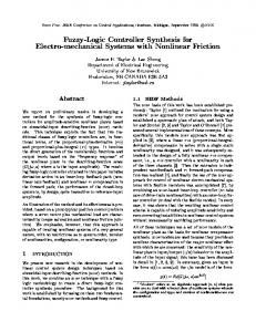
Fig.9. (a)Fuzzy logic 49 rules, (b)Fuzzy logic 9 rules, zoom in for different type of load torque
300
speed(rad/s)
200
Fig.9. shows the effect of load variation of both “standard” and “case design” in order to test the robustness of the proposed controller. From this figures, it show that, the “case design” with 9 rules give better response in term of less undershoot at t=0.9s compared to “standard design”. This is due to the number of rules that the system need to calculate is much lower in the case of “9 rules” compared to “49 rules”. These figures also prove that, the higher load applied, the more severe impact to the system.
100 Fuzzy logic 49 rules
speed reference
0 Fuzzy logic 9 rules
-100 -200 -300 0.15
0.2
0.25
0.3
0.35
0.4
time(s) (c) 220
speed reference
(a) Fuzzy 9 rules TL=4Nm
400
150% of rated speed 100% of rated speed
180
200
Fuzzy 49 rules TL=4Nm
160 Fuzzy logic 9 rules TL=8Nm
140 120 0.88
0.92
0
-200
Fuzzy logic 49 rules TL=8Nm
0.9
50% of rated speed
speed(rad/s)
speed(rad/s)
200
0.94 time(s)
0.96
0.98
1 -400 0
0.2
0.4
0.6
0.8
1
time(s)
Fig.8. Speed responses comparison (a) during start-up (b) during reverse operation and (c) during variation of load disturbance for Fuzzy logic 49 rules and Fuzzy logic 9 rules
(b) sp e e d (ra d /s)
400
Fig.8. shows that, the proposed Fuzzy logic design using 9 rules gives better performance compared to standard design with 49 rules, in term of rise time. Both designs are good enough so, that no overshoot happen during start-up and reverse operation. Only for the case of different load applied, both motors will produce small undershoot responses before get it steady-state operation after 0.06s. (a)
150% of rated speed 100% of rated speed
200
50% of rated speed
0
-200 -400 0
0.2
0.4
0.6 0.8 1 time(s) Fig.10. (a) Fuzzy logic 49 rules, (b)Fuzzy logic 9 rules, zoom in for different type of rated speed at rated torque (TLm1=8Nm, TLm2=4Nm)
220
Fig.10. proves the robustness of the Fuzzy logic controller, which both designs produce almost consistent undershoot for wide range of different speed, and able stable again after several millisecond (≈0.06s) after unbalance load condition.
sp e e d (ra d /s)
200 180 160
speed reference m1 : TL=1Nm m2 : TL=0.5Nm m2 : TL=4Nm m1 : TL=8Nm (rated torque)
140 120 0.85
0.9
0.95
V. CONCLUSION This paper presents the results of a detailed comparative study on Fuzzy logic speed controller in Dual PMSM drives. Two fuzzy speed controllers which are ‘standard design – 49 rules’ and ‘case design -9 rules’ are studied. Performance of both designs are compared for different type of load disturbance and for wide range
1
time(s)
(b)
256
World Academy of Science, Engineering and Technology 53 2011
of speed. The simulation study is realized in MATLAB/Simulink environment. Detailed comparison of performances over the several tests shows that both designs of controllers produce nearly identical performance, thus it is feasible to minimize the complexity of Fuzzy logic controller by reducing the number of fuzzy rule-basse from 49 rules to 9 rules especially for the case of dual PMSM drives. REFERENCES [1]
[2]
[3]
[4]
[5]
[6]
[7]
[8]
[9]
[10]
[11]
[12]
[13]
[14] [15]
[16]
Z. Li and S. Fengchun, "Torque control of dual induction motors independent drive for tracked vehicle," in 2008 10th Intl. Conf. on Control, Automation, Robotics and Vision, 2009, pp. 68-72. Y. He, et al., "A comparative study of space vector PWM strategy for dual three-phase permanent-magnet synchronous motor drives," in Applied Power Electronics Conference and Exposition (APEC), 2010 Twenty-Fifth: Annual IEEE., 2010, pp. 915-919. M. Acampa, et al., "Optimized control technique of single inverter dual motor AC-brushless drives," in Universities Power Engineering Conference, 2008, UPEC 2008, 2008, pp. 1-6. M. Acampa, et al., "Predictive control technique of single inverter dual motor AC-brushless drives," in Proceeding of the 2008 International Conference on Electrical MAchines, 2008, pp. 1-6. D. I. A.Del Pizzo, I.Spina, "Optimum Torque/Current control of dual PMSM single VSI Drive," 15th International Symposium on Power Electronics-Ee 2009, Novi Sad, Republic of Srbia, October 28th-30th ,2009 2009. A. Del Pizzo, et al., "High performance control technique for unbalanced operations of single-vsi dual-PM brushles motor drives," in 2010 IEEE International Symposium on Industrial Electronics (ISIE), 2010, pp. 1302-1307. W. Da Silva and P. Acarnley, "Fuzzy logic controlled dc motor drive in the presence of load disturbance," in 7th European Power Electronics Conference, 1997, pp. 2-2. Y. C. Hsu, et al., "A fuzzy adaptive variable structure controller with applications to robot manipulators," Systems, Man, and Cybernetics, Part B: Cybernetics, IEEE Transactions on, vol. 31, pp. 331-340, 2002. V. Kumar, "Hybrid Controller based Intelligent Speed Control of Induction Motor 1," Journal of Theoritical and Applied Information Technology, JATIT (2005-2009). H. Mohamed and W. Hew, "A fuzzy logic vector control of induction motor," in TENCON 2000. Proceedings, 2002, pp. 324328. M. N. Uddin, et al., "Performances of fuzzy-logic-based indirect vector control for induction motor drive," Industry Applications, IEEE Transactions on, vol. 38, pp. 1219-1225, 2002. A. Karakaya and E. Katakas, "Performance Analysis of PM Synchronous Motors Using Fuzzy Logic and Self Tuning Fuzzy PI Speed Controls," Arabian Journal for Science and Engineering, vol. 33, pp. 153-178, 2008. A. Ghani, et al., "A FUZZY LOGIC CONTROLLER FOR SYNCHRONOUS MACHINE," Journal of Electrical Engineering,2007. R. N. Tuncay, et al., "Rapid control prototyping approach to fuzzy speed control of brushless DC Motor," ELECO’03, 2003. M. Rodrigues, et al., "Fuzzy logic control of a switched reluctance motor," in Proc. ISIE'97, 2002, pp. 527-531.Y. Zhang, et al., "High Performance Position Control System Based on SR-PM Motor*," Tsinghua Science & Technology, vol. 12, pp. 614-619, 2007. I. Guney, et al., "Dynamic behaviour model of permanent magnet synchronous motor fed by PWM inverter and fuzzy logic controller for stator phase current, flux and torque control of PMSM," in Proc. IEMDC'01, 2002, pp. 479-485.
257