Proceedings of the 3 International Modelica Conference, Linköping, November 3-4, 2003, Peter Fritzson (editor) rd
Andreas Idebrant and Lennart Näs MathCore Engineering AB; Alstom Industrial Turbines AB, Sweden: Gas Turbine Applications using ThermoFluid pp. 359-366
Paper presented at the 3rd International Modelica Conference, November 3-4, 2003, Linköpings Universitet, Linköping, Sweden, organized by The Modelica Association and Institutionen för datavetenskap, Linköpings universitet All papers of this conference can be downloaded from http://www.Modelica.org/Conference2003/papers.shtml Program Committee Peter Fritzson, PELAB, Department of Computer and Information Science, Linköping University, Sweden (Chairman of the committee). Bernhard Bachmann, Fachhochschule Bielefeld, Bielefeld, Germany. Hilding Elmqvist, Dynasim AB, Sweden. Martin Otter, Institute of Robotics and Mechatronics at DLR Research Center, Oberpfaffenhofen, Germany. Michael Tiller, Ford Motor Company, Dearborn, USA. Hubertus Tummescheit, UTRC, Hartford, USA, and PELAB, Department of Computer and Information Science, Linköping University, Sweden. Local Organization: Vadim Engelson (Chairman of local organization), Bodil Mattsson-Kihlström, Peter Fritzson.
Andreas Idebrant and Lennart Näs
Gas Turbine Applications using ThermoFluid
Gas Turbine Applications using ThermoFluid Andreas Idebrant
[email protected] MathCore Engineering AB Teknikringen 1B, SE-583 30 Linköping, Sweden http://www.mathcore.com
Abstract In a project between MathCore Engineering and Alstom POWER Sweden in Finspång Sweden, a Modelica model of a complete 43 MW gas turbine has been made. The main purpose of this model is to study transients under different working conditions. The model can be used to optimize start-up sequence, simulate load rejections, verify design, test different fuels etc. A new library called GasTurbine containing components specialized for gas turbine modeling has been developed based on the existing public available ThermoFluid[1, 2] library.
1 Introduction In this paper the modeling issues, using the ThermoFluid library, of a large industrial gas turbine are addressed. The gas turbine is the 43 MW GTX 100 from Alstom POWER in Sweden. This type of gas turbine is used for producing power to an external or internal electrical grid. The main fuel is natural gas or diesel oil. Testing of such big gas turbines in a separate test rig or at each specific site is costly and time consuming. Transient tests might also lead to performance degradation. A detailed dynamic model of a gas turbine could simulate and hereby prevent possible problems before they occur in real life. The ThermoFluid library contains the framework for building thermodynamic applications such as a gas turbine in Modelica. ThermoFluid has also been used in previous projects to build gas turbines[3, 4]. Combined with the Modelica standard library it is possible to connect to other domains such as electrical grid nets, an electrical motor, control systems, etc. Unfortunately the ThermoFluid library is complex to use even for an experienced user, familiar with Modelica. It does not contain the blocks needed to build a complete gas turbine. Therefore an
The Modelica Association
Lennart Näs
[email protected] Alstom Industrial Turbines AB SE-612 82 Finspång, Sweden http://www.power.alstom.com
application library called GasTurbine has been made that is more easy to use and contains ready to use components especially designed for gas turbine applications. The current library contains about 100 components. There were mainly two objectives with this project. The first objective was to make an existing model of a reference model made in a static simulation tool called IPSEpro[5]. This tool is a suitable tool for thermodynamic processes in general and it has in Finspång been added a library for gas turbine components. Complete static models of the Finspång gas turbine fleet are frequently used and tuned to correspond to real engine behavior. This kind of static tool is used to e.g. predict power output of a gas turbine at given conditions. The input data could be fuel type, air temperature, ambient pressure, component performance etc. The target for the model in Modelica was to have the steady state points identical to the result from the static model in IPSEpro. This was done step by step by verifying the calculation model and the gas routines for each component in the GasTurbine library. The second objective was to make a simulation of a load rejection where the outlet power to a simulated electrical grid is disconnected instantly and a controller makes sure that the increasing rotational speed will be limited. The controller and the fuel gas system implemented in the Modelica model are built up identical as for the “real” engine.
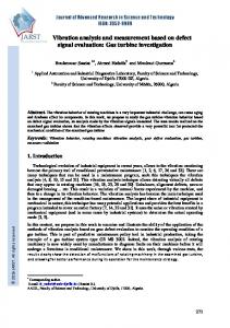
2 The Gas Turbine Figure 1 shows a cross-section diagram of the gas turbine GTX100. It is a middle range machine with maximum sustained output of 43MW. The main parts are the compressor, combustor, and the turbine. A simplified diagram of such a gas turbine is shown in Figure 2.
Modelica 2003, November 3-4, 2003
Andreas Idebrant and Lennart Näs
Gas Turbine Applications using ThermoFluid
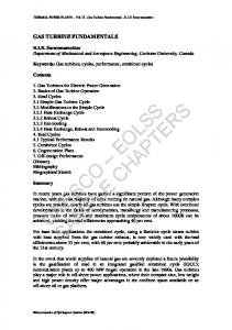
compressor (p3), and temperature after the turbine (t7). The outputs are the pilot fuel valve opening (xgp), main fuel valve opening (xgm), and the guide vein opening (IGV).
Figure 1: A cross-section diagram of the gas turbine GTX100 developed by Alstom POWER in Finspång Sweden.
The cycle starts with ambient air flowing into the compressor. The compressor increases pressure and temperature of the air. At the next stage, pressurized air and fuel are mixed in the combustion chamber and burnt with constant pressure. The resulting hot exhaust gas is expanded in the turbine stage and is released to the environment. The produced power is converted to electrical power in a generator connected to the outgoing shaft.
Figure 3: The controller block for GTX 100.
To be able to simulate load drops a simple model of a virtual grid was implemented. The basic idea is to use a clutch model to detach the mechanical flange from the simulated grid at a predefined instant. A simple PI controller attached to a variable damper is used to gradually increase the power output of the generator, see Figure 4.
Fuel
Compressed air
Combustion chamber
Exhaust gas
Power output
Air Compressor
Turbine
Exhaust
Figure 2: A schematic picture of a gas turbine.
The complete model of a gas turbine is of course more advanced. The real gas turbine consists of a quite advanced cooling system with bleed outputs from the compressor and a detailed fuel system. A controller adjusts the amount of fuel and controls the guide veins in the compressor. The different sub systems are explained in the next sections.
3 Controller The controller used in this model is the same used in the “real” gas turbine. It is not complete and works only when the model is working at sustained conditions. For start up purposes there is an additional controller, which has not been implemented. The controller block can be seen in Figure 3. On the left side there are parameter inputs for ambient conditions. On the lower side there are inputs for power produced to the grid (P_el), rotational frequency (f), pressure after the The Modelica Association
Figure 4: Controller part for simulating a grid net and load drop/rejection.
4 Fuel system The real fuel system of a gas turbine is quite complex with a lot of pipes and valves with different physical properties. A simplified model has been made, which will be sufficient for these types of simulations. The structure of the simplified fuel system can be seen in Figure 5. The pilot and main valve is connected to the main controller in the total model.
Modelica 2003, November 3-4, 2003
Andreas Idebrant and Lennart Näs
Gas Turbine Applications using ThermoFluid
m_out[H2O], m_out[N2], and m_out[O2] are the outgoing mass flows for Ar, CO2, H2O, N2, and O2 respectively. Similarly, the notation m_air and m_fuel denote the mass flows for air and fuel.
5 Cooling system
Figure 5: Picture of the simplified fuel system.
For combustion natural gas has been used with the substances C2H6, C3H8, CH4, CO2, and N2. The air that flows into the combustion chamber consists of the following substances: Ar, CO2, H2O, N2, and O2. During combustion of the gas mix the following reactions occur (Ar and N2 does not react):
The cooling system consists of pipes (mixers and splitters) and volumes. Cooling increases the efficiency of the gas turbine. Air from the compressor and its bleed outputs is used to cool the exhausts from the combustion chamber. There are also some small flows directly to the ambient air. The volumes and valves are taken from the ThermoFluid library and have been modified to use the correct medium model. Since the exhaust gas and the air has the same composition in this case (but different mass fractions) the same medium model is used for air and exhaust gas. Figure 6 shows a typical implementation of a mixer that mixes gases with the same composition.
Ar → Ar CH4 + 2 O2 → 2 H2O + CO2 C2H6 + 3.5 O2 → 2 CO2 + 3 H2O C3H8 + 5 H2O → 3 CO2 + 4 H2O N2 → N2 These reactions can be transformed to expressions for mass flow in Modelica syntax according to below: m_out[Ar] = m_air[Ar]; m_out[CO2] = m_air[CO2] + m_fuel[CO2] + (wCO2/wCH4)*m_fuel[CH2] + 2*(wCO2/wC2H6)*m_fuel[C2H6] + 3*(wH2O/wC3H8)*m_fuel[C2H6]; m_out[H2O] = m_air[H2O] + 2*(wH2O/wCH4)*m_fuel[CH4] + 3*(wH20/wC2H6)*m_fuel[C2H6] + 4*(wH20/wC3H8)*m_fuel[C3H8]; m_out[N2] = m_air[N2] + m_fuel[N2]; m_out[O2] = m_air[O2] – (wO2/CH4)*m_fuel[CH4] – 3.5*(wO2/wC2H6)*m_fuel[C2H6] – 5*(wO2/wC3H8)*m_fuel[C3H8];
The notations wCH4, wC2H6, wC3H8, wCO2, wH20, and wO2 denote the molecular weights for CH4, C2H6, C3H8, CO2, H20, and O2 respectively. The mass flows m_out[Ar], m_out[CO2],
The Modelica Association
Figure 6: A mixer with three inputs and one output.
The splitting fracture of gases is controlled by adjusting the nominal mass flow rate at a given nominal pressure drop level. The diagram picture of a splitter is shown in Figure 7.
Figure 7: A splitter with one input and three outputs.
The complete cooling system can be seen in Figure 8.
6 The Modelica model The complete Modelica model of the gas turbine is shown in Figure 8. The model consists of a controller, simulated grid, fuel system, cooling system, and the basic gas turbine part.
Modelica 2003, November 3-4, 2003
Andreas Idebrant and Lennart Näs
Gas Turbine Applications using ThermoFluid
Figure 8: The complete Modelica model of a GTX100 gas turbine with controller, fuel system, cooling system and simulated grid.
For the thermodynamic parts of the model the connector for static momentum balance from the ThermoFluid library is used: connector BaseFlow parameter Integer nspecies(min=1); parameter String MediumType = "unspecified"; SIunits.MassFraction mass_x[nspecies]; SIunits.Pressure p; SIunits.SpecificEnthalpy h; flow SIunits.MassFlowRate mdot_x[nspecies]; flow SIunits.Power q_conv; SIunits.Density d; SIunits.Temp_K T; SIunits.RatioOfSpecificHeatCapacities kappa; SIunits.SpecificEntropy s; end BaseFlow;
This means that no dynamic momentum terms are taken into account in this model. This choice was initially made to reduce the computational burden. The complete model in Figure 8 has 240 continous time states and 2644 nontrivial equations. Due to the detailed cooling system, the Modelica model is hard to initialize. It is of great importance to choose the initial starting parameters carefully to avoid a stiff system. To get rid of the sometimes long initialization times, the model was once simulated past the inital stiff part. Then the simulation was stopped and the current state was The Modelica Association
saved to a file, e.g. dsfinal.txt. In the next run the model states were initialized with the previously saved file and the simulation started much faster.
7 The GasTurbine Library The Modelica library ThermoFluid was used as a toolbox for creating the components needed for the project. Currently, ThermoFluid does not contain ready made components needed for gas turbine modeling. Therefore an application library called GasTurbine (Figure 9) was created with specialized, ready to use components for gas turbines and especially for the GTX100. The current library consists of about 100 components for gas turbine applications.
Figure 9: Overview of the GasTurbine library.
The detail of the models varies from simple compressors without maps to more advanced with inlet guide veins, maps, and bleed outputs.
Modelica 2003, November 3-4, 2003
Andreas Idebrant and Lennart Näs
Gas Turbine Applications using ThermoFluid
8 Verification
Figure 10: Sample components from the GasTurbine library.
The design of the library was developed with the end user in mind and all components can be connected directly without the need to redeclare or modify any part of the model.
A model can only be trusted if you can verify that the results produced from the model are valid. In this case data from a similar static model of GTX100 in the program IPSEpro was used. This means that only steady state values can be verified by this comparison but similarity in steady state points indicates that at least agreement in the handling of physical properties and calculation models. In the future real data from live experiments will be used to verify also the conditions during transients. When studying transients it is important that the dynamic parts in the model are accurate, e.g. the volumes and inertias. These dynamic parts do not make any significant impact on the static results.
Figure 11: The model used for verification purposes, i.e. with IPSEpro.
The medium models used in the two models are not entirely identical. In IPSEpro the Janaf tables are used and in TermoFluid the NASA tables. The small differences can however be neglected. The comparison between the two models has been
The Modelica Association
conducted with identical air and fuel composition. Below is an example table with results from the combustion chamber. Note that the pressure and mass flow are set to parameters (or input values) in IPSEpro to get the same steady state level:
Modelica 2003, November 3-4, 2003
Andreas Idebrant and Lennart Näs
Gas Turbine Applications using ThermoFluid
Inlet combustor Variable Pressure [bar]*
ThermoFluid IPSEpro Error [%] 13,4 13,4 0
Temperature [°C] Mass flow [kg/s]* Entropy [J/K] Kappa R
439,2 74,11 7097 1,360 289,0
435,9 74,11 7089 1,360 289,0
-0,75 0 -0,12 0,046 -0,0015
Outlet combustor Variable
ThermoFluid IPSEpro Error [%]
Pressure [bar] Temperature [°C] Mass flow [kg/s] Entropy [J/K] Kappa R
13,31 949,3 75,11 7824 1,308 291,6
13,31 0,023 947,7 -0,17 75,11 -0,00067 7847 0,30 1,309 0,069 291,6 -0,0013
Table 1: Verification results ThermoFluid versus IPSEpro. *Input values (parameters) in IPSEpro.
Table 1 shows that there are minor differences between the two tools, which is not fully satisfactory in the work with having the two models being a reflection of one other, but the accuracy is considered as sufficient to rely on the Modelica model from a dynamic point of view.
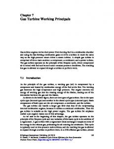
9 Load Rejection One important thing to test for new gas turbines is its capability to handle full load rejections/drops without tripping. In many cases it is considered as most vital to have the gas turbine back on the grid, producing full power in as short time as possible. A load drop is what happens when a power failure occurs. It could be due to lightning strikes, mechanical failure etc. When the gas turbine is running at full working power, e.g. 43MW, one want to make sure that the gas turbine does not reach trip speed when a power output to the grid is suddenly lost. The immediate result is that the rotational velocity increases to a certain level that could be close to trip level.
Figure 12: The Modelica model used for load drop/rejection simulations.
To avoid this a controller is designed to as fast as possible detect this failure and reduce the fuel input to the combustor and then lower the speed. The model used for this testing is shown in Figure 12. It is also important to have enough fuel so that the rotational speed remains at the working speed, e.g.
The Modelica Association
6600rpm, and make sure that the combustor still operates. The trick is to shut down the main fuel valve and open the pilot fuel valve to ensure that the combustor is not shut down. Figure 13 shows a whole operating cycle in an assumed “weak” local
Modelica 2003, November 3-4, 2003
Andreas Idebrant and Lennart Näs
Gas Turbine Applications using ThermoFluid
grid (island mode), from ignition, loading, fuel valve switching and a full load drop at the end.
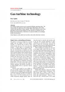
Figure 15: Generated power to the grid. Figure 13: The rotational speed of the shaft during a load rejection test.
The first 50 seconds the gas turbine spins up to its working speed at 6600rpm. Then the generator starts to produce power and a sudden drop in rotational speed can then be seen until the controller brings the speed back to normal. At around 190 seconds the power has increased to about 37MW and the pilot fuel is shut down and is replaced with more main fuel, see Figure 14.
Figure 14: Percentage of valve opening during a load drop simulation. Pilot valve opening is dashed.
It can here be seen as a decrease in speed due to that the valve switching sequence is not tuned in the model and hereby the fuel flow is not constant during this process. When the full power has been reached at about 350 seconds a power failure occurs, i.e. the generator effect is decoupled, see Figure 15, and the rotational speed increases dramatically. Instantaneously, the controller reacts and shuts down the main fuel and starts feeding the combustor with pilot fuel and the rotational speed decreases to normal 6600rpm.
The Modelica Association
The requirement for this load rejection test is that the rotational speed must not exceed 10% of the nominal value. In this case the rotational speed must not exceed 6600*1.1=7260rpm. The test shows that the maximum speed is about 6970rpm, which is acceptable. This load drop experiment has been conducted with real gas turbines and a value around 7000rpm has been a normal value for the GTX100.
10 Conclusions In this article the building of a gas turbine model in Modelica has been described. A new library called GasTurbine has been developed to modify existing models in ThermoFluid to gas turbine applications. The experience is that the ThermoFluid library is somewhat hard to work with for a non-Modelica library developer and the GasTurbine library is more suited for the end user. The gas turbine model has been verified with a static tool called IPSEpro with acceptable results from a dynamic point of view. A load rejection test has been performed with results similar to a real gas turbine. At the end Modelica has been proven to be a suitable tool for building gas turbines in an object oriented way. The simulations are quite fast considering the amount of computations in the large model. Finding suitable initial values can be hard but new language constructs in Modelica has been introduced to help the end user to initialize models in a more convenient way.
Modelica 2003, November 3-4, 2003
Andreas Idebrant and Lennart Näs
Gas Turbine Applications using ThermoFluid
11 References [1] H.Tummescheit, J. Eborn, F.J. Wagner: “Development of a Modelica Base Library for Modeling of Thermo-Hydraulic Systems”. Modelica Workshop 2000 Proceedings, pp. 4151. [2] H.Tummescheit: “Design and Implementation of Object-Oriented Model Libraries using Modelica”. PhD thesis. Department of Automatic Control Lund Institute of Technology Lund, August 2002. [3] Pérez Gómez A.A: “Modelling of a Gas Turbine with ModelicaTM”. Master thesis. Department of Automatic Control Lund Institute of Technology Lund, May 2001. [4] S.Haugwitz: “Modeling of Microturbine Systems”. Master thesis. Department of Automatic Control Lund Institute of Technology Lund, May 2002. [5] IPSEpro is developed by SimTech Simulation Technology (http://www.simtechnology.com)
The Modelica Association
Modelica 2003, November 3-4, 2003