RESEARCH ARTICLE
Geomorphological and petrological observations along a segment of slow-spreading Carlsberg Ridge A. V. Mudholkar*, V. N. Kodagali, K. A. Kamesh Raju, A. B. Valsangkar, G. H. Ranade and N. V. Ambre National Institute of Oceanography, Dona Paula, Goa 403 004, India
A 120-km-long section of the Carlsberg Ridge has been mapped with multi-beam bathymetry system (MBS). High resolution bathymetric contour map generated with the MBS data shows well-defined axial valley bordered by steep valley walls and the presence of a ridge axial discontinuity in the southeast end of the survey area. This discontinuity represents the propagating ridge head present along the ridge axis and is being reported for the first time along an active ridge segment of the Carlsberg Ridge. The pseudo-side scan image reveals a wellsedimented axial valley. It is for the first time that various upper mantle (serpentinites and peridotites) and lower crustal rocks (gabbros) have been recovered from this part of the Carlsberg Ridge apart from the ridge basalts. The basaltic rocks are mostly fresh; however a few types of basalt exhibit alteration. Serpentinites and peridotites are almost totally altered and exhibit the stress they have undergone during and after the emplacement. THE Carlsberg Ridge (CR) forms the northern section of the Indian Ocean Ridge system and acts as a boundary between the African plate and the Indian plate. CR is bounded on north by the Owen Fracture Zone (OFZ), which offsets the CR by about 300–350 km before it enters the Red Sea. At the equator, the trend of the CR gradually changes from NW–SE to N–S where it joins the Central Indian Ridge (CIR). Indian Ocean Ridge system, in general, is less explored and sampled, compared to individual ridge segments of Mid-Atlantic Ridge (MAR) which are being surveyed in great detail with the help of submersibles and other advanced techniques. The CR is similar in structure to MAR, as the spreading rates are comparable (half spreading rate 14 mm/yr; ref. 1). Under the IndRidge programme, initiated by the National Institute of Oceanography, Goa, with the support of the Department of Ocean Development, one of the least-studied ridge segments of the Carlsberg Ridge, has been mapped and explored systematically.
*For correspondence. (e-mail:
[email protected]) 982
Wiseman2 was the first to sample the rocks from the CR and describe different types of basalts such as augite basalts, variolitic basalts and hornblende-augite basalts. He analysed some of these basalts and concluded that they were compositionally similar to the basalts collected from the Atlantic and Pacific Ocean. Matthews et al.3 surveyed the crest area of the CR at ~ 5°N and acquired bathymetry and magnetics. They identified a minor transform fault with a displacement of about 10 miles. In recent times, Chaubey et al.4 , Ramana et al.5 and Mercuriev et al.6 have carried out geophysical studies along the CR. Matthews et al.3 reported fresh basalts, metamorphosed basalts and observed brecciation and hydrothermal alteration of the crustal rocks. Cann and Vine7 gave detailed petrography of basalts, serpentinites and hornblende-gabbro collected from the same area. They reported that basalts have undergone greenschist facies metamorphism. Frey et al.8 studied the basalts drilled on the flanks of the CR, in Arabian Basin (DSDP Holes 220 and 221) and Somali basin (Holes 235, 236 and 240), and observed the heterogeneities at the source for the CR basalts. Bonatti9 , Bonatti et al.10 , and Hamlyn and Bonatti11 gave detailed account of the plutonic ultramafic rocks exposed on the fault scarp of the OFZ and their mineralogy and composition. They attributed the exposure of these mantle rocks to the tectonic upliftment along the fracture zone. Engel and Fisher12 reported similar assemblages of mantle rocks (from granite to serpentinites) from various ridge segments of the Central Indian Ridge from the Vema trench, the deepest location along the CIR. Banerjee and Iyer13 studied basalts from CR and observed the chemical and mineralogical affinity to basalts from other segments of the Indian Ocean ridge system. Iyer and Banerjee14 have concluded a low pressure evolution for the basalts from the CR with magma mixing. However, there are no reports of the ultramafic rocks associated with the ridge basalts from the CR except from the OFZ10,11 where full section of the oceanic crust is exposed. Here, we report geomorphological set up of a section of CR along with the petrographical observations of the mantle rocks and ridge basalts recovered from the axial valley. CURRENT SCIENCE, VOL. 82, NO. 8, 25 APRIL 2002
RESEARCH ARTICLE
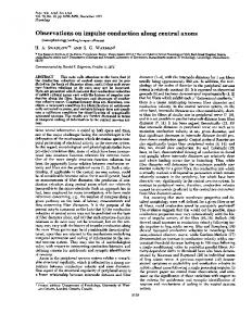
Figure 1. Bathymetric map of the surveyed segment of CR (Contour interval = 250 m). A–A′, B–B′, C–C′ and D–D′ are the sections perpendicular to the ridge axial valley. Sections A–A′, B–B′, C–C′ and D–D′ are referred to as sections A, B, C and D in Figure 2 and in text respectively. ê = dredging location. Thick dashed line is the trace of the axial valley. Thinner dashed line is the oblique structure representing the propagating head.
Methodology During the ORV Sagar Kanya cruise no. 114, about ~ 120 km length of the CR was surveyed. General trend of the ridge was ascertained with the help of the GEOSAT gravity data and the survey lines were planned perpendicular to the ridge axis. Multi-beam bathymetry system (MBS), Hydrosweep, provides coverage equal to twice the water depth. The spacing between the survey lines was kept at 3 nautical miles to achieve total (i.e. hundred per cent) coverage of the area. Gravity, magnetic and 12 kHz single-beam echosounder data were also acquired along with MBS data. The GPS (Magnavox, MX-4400) system was used for the navigational control. Sampling locations were selected based on the online MBS data. A total of about 2872 line kilometre data and approximately 15,000 km2 area along the axial zone of CR were surveyed during the cruise. Rock samples were recovered by the chain-bag dredge from three sites (DR-1, -2, and -3) within the axial valley of the surveyed segment of the CR. Figure 1 shows depth contour map of the area with dredge locations. For the petrographical observations, thin sections of the rocks were prepared and observed under CURRENT SCIENCE, VOL. 82, NO. 8, 25 APRIL 2002
petrological microscope to record the minerals present and their relationship with each other and the effects of alteration.
Geomorphological observations As the CR is a slow-spreading ridge, the topography developed is of rugged nature, which is reflected in the contour pattern of the surveyed area of the ridge. The depth varies from 4700 m within the axial valley in the south-eastern side to a shallow peak of about 1800 m on the ridge flank (Figure 1). Four bathymetric sections (A, B, C, and D) across the CR segment are presented in Figure 2. The linearity of the contours in NW–SE direction documents the general NW–SE trend of the CR. The axial valley, with an average depth of about 3500 m, is bounded on both sides by steep valley walls that rise to about 2500 m water depth, indicating that valley walls are ~ 1000 m high. Such a rugged/rough geomorphology is generally seen along the slow-spreading ridges. Within the northwestern part of the axial valley shallow axial highs of about 100 m height are observed (Figure 1), which indicate thickening of the ridge 983
RESEARCH ARTICLE
Figure 2. Topographic sections across the ridge axial valley as shown in Figure 1. Section A–A′′ , Wider axial valley bounded on both sides by steep valley walls. Axial valley floor has neo-volcanic highs. Section B–B ′ , Topographic section from the hills composed of ultramafics serpentinites and gabbros. Two identical highs within the axial valley on the edges separated by the axial valley are seen. In this section a good correlation is observed with relation to the uniform spreading of the ridge. Section C–C ′ , Section through the nontransform discontinuity with an isolated topographic high separating two geomorphic lows. IC, inside corner. Section D–D′′ , Section through the southern segment with narrow axial valley and steep western valley wall rising up to ~ 1800 m. IC, inside corner.
segment. Such thickening and shallowing of the axial valley is noticed near the central part of the MidAtlantic ridge segment15 . Along the ridge flanks, the topographical highs and lows show ridge parallel linear trend. The depth on the northern flank of the ridge is more than the southern flank at the same distance from the ridge axis. Near the north-western edge of the area, depth of the axial valley increases (4050 m) and the width reduces gradually to about 10 km. These observations point to the possible ridge segment termination close to the northern end. The northern ridge segment abuts a topographic high of about 1800 m near 3°32′N; 63°36′E. This topographic high is observed on the southern valley wall close to the RAD (Figure 1, Section D). A prominent topographic feature at the south-eastern region of the survey area is a discontinuity in the trend of the ridge axial valley along which the ridge axis is offset by about 22 km (Figure 1). Kamesh Raju et al.1 have interpreted this discontinuity as Non-Transform Discontinuity (NTD). These NTDs are also called Ridge Axial Discontinuities (RADs). At RAD, the axial valleys of both northern and southern ridge segments have merged and the total width of the axial zone is observed to be ~ 38–40 km. The topography near the RAD is 984
much more rugged than that observed along the ridge flanks. The axial valley wall of the southern ridge segment is steeper compared to the northern ridge segment, and the deepest ridge axial floor of 4700 m next to a topographic high with the depth ~ 1800 m (Figure 1) is encountered. Toward the north and south of the RAD, distinct variation in width of the axial valley is noticed. The width of the axial valley, immediately to the north of RAD is narrow (~ 7 km) (Figure 2) while it is wider (~ 16 km) farther in the north (Figure 2, Section A, B). An interesting geomorphic feature, oblique to the trend of the NW–SE trending rift valley, is observed in the contour map and is shown by thin dash lines on both sides of the axial valley in Figure 1. This geomorphic feature is a linear feature bounded by the 3000 m contour and is at an angle of ~ 30° to the trend of the axial valley. This V-shaped feature begins close to the RAD. This feature might have been developed due to the propagating ridge head present along the Carlsberg Ridge. Mutter and Karson16 have suggested that the V-shape represents the wake of the propagating ridge. Similar propagating ridge heads have been reported from the Mid-Atlantic Ridge17 , southeast Indian Ridge18 and also on the eastern distal flanks of the Carlsberg Ridge19,20. The implications of the propagating ridge head are under detailed analysis. An elongate topographic high of about 500–600 m high and about 14–15 km long terminated by a deep of ~ 4300 m is observed, just above the RAD close to the western valley wall of the northern ridge segment (Figure 1, DR-1). Another interesting feature along this ridge segment is a topographic high as described earlier at the Outside Corner (OC) of the RAD. This high, according to Tucholke and Lin21 , might be composed of ultramafic rocks, though at present we have not sampled this feature. In future we plan to collect sample from this high. It will be interesting to decipher the tectonic activity that emplaced these rocks along the outside corner of the discontinuity. We hope to get the ultramafic rocks from this topographic high. Similar highs near the RADs are composed of ultramafic rocks and they are termed as ultramafic topographic high22 . It is important to know the petrological composition of this ultramafic topographic high. The topographic sections across the ridge presented in Figure 2, show the changes in the topography along the surveyed ridge segment. These sections point out the changes in the width of the axial valley, narrow (~ 7 km) near the RAD and wider ~ 16 km at the farthest end of northern ridge segment. The topographic section along the ridge discontinuity reveals a very interesting topographic feature wherein no clear single ridge axial valley can be deciphered. However, a welldefined axial valley is observed in other sections. Along section C, an isolated topographic high reaching to CURRENT SCIENCE, VOL. 82, NO. 8, 25 APRIL 2002
RESEARCH ARTICLE ~ 2200 m separates two topographic lows on both flanks of the ridge axial valley. This high is towards the eastern inside corner of the RAD flank where the southern ridge segment shifts its axial valley. However, the topographic high of ~ 1800 m on the western valley wall (along section D) abuts the northern ridge segment. The western side topographic low in Section C may be the trace of the northern axial ridge valley. However, the eastern side low is the topographic low present along the ridge flank at RAD. The section D reveals a steep western wall rising from a depth of about 4700 m to the shallowest part of the surveyed area of about ~ 1800 m. However, the eastern valley wall does not have such a steep gradient.
Pseudo-side scan sonar image observations Multi-beam data collected using the Hydrosweep system, provides Root Mean Square (RMS) amplitude values of all 59 beams per ping in addition to the depth data. This amplitude data was used to generate the pseudo-side scan image of the seafloor23 (Figure 3). The backscattered strength of the echo is indicative of the nature or type of seafloor. A strong reflected echo gives dark grey-to-black tone, meaning, less absorption by seafloor. Sedimented seafloor displays light grey tone in the image due to the absorption of the echo energy by sediment. The pseudo-side scan image of the study area indicates that the axial valley is covered by sediment, which is represented in the form of a wide linear grey
Figure 3. Pseudo-side scan image of the area after back-scatter strength of the echo is measured and mapped. Light and dark tone of the seafloor indicate sediment and exposures of the rocks respectively. Axial valley is sedimented and along the ridge flanks zebralike pattern is seen due to the alternate rock and sediment exposures. CURRENT SCIENCE, VOL. 82, NO. 8, 25 APRIL 2002
toned area. A small sediment core (~ 40 cm long) has been collected within the axial valley, confirming the presence of sediment. The thickness of the sediment has not been determined but it can be firmly said that the axial valley is sedimented as observed in Kane Fracture Zone24 . This indicates that there were no fresh lava eruptions or no magmatic construction on a large scale within the axial valley. However, presence of the sediment within the axial valley does not mean that the tectonic and magmatic activity at CR is ceased. In fact, within the axial valley, small patches of strong reflections are observed which might be due to reflections from the fresh lava outpourings. We have also collected fresh sheet basalt within the axial valley. With the help of the pseudo-side scan image, many small and prominent features could be detected, which otherwise would not have been possible to detect by the contour map alone. The pseudo-side scan image complements the contour map in identifying small neovolcanic cones and axial highs within the axial valley of such a rugged type of bathymetry at CR. The pseudoside scan image of the area also exhibits ridge parallel alternate black and white zebra-like pattern indicating alternate elongate ridge parallel rock exposures and sediment filled troughs. These are due to the troughs developed between the rocky highs where sediment gets deposited.
Macroscopic description of rocks The dredging locations are shown in Figure 1 and the general macro- and micro-scopic description of the basalts and other rocks recovered is given in Table 1. The dredge track for DR-1 was along the linear topographic high inside the western wall of the rift valley, starting from ~ 3400 m, i.e. valley floor to ~ 3000 m depth (Figure 1), almost top of the linear mount. In this dredge, mantle rocks such as serpentinites and gabbros, along with the variety of basalts such as pillow basalts, block basalts, etc., were recovered. In general, basalts recovered from the axial valley floor show the presence of sediment within the cracks and joints indicating that thin sediment covered the basalts. The mantle rocks might be exposed on the elongated rise. Fresh lava tongues of plagioclase phyric basalts have also been recovered. Alteration of the basalts by seawater is observed especially along the cracks or joints in basalts. The fresh glass, formed due to the chilling effect of the bottom cold seawater on the effusing lava, is observable on almost all the basalts recovered. Apart from ridge basalts, ultramafic rocks such as harzburgites, serpentinites and gabbros were also recovered from this station. At this site, the abundance of serpentinites and lherzolites over the gabbros indicate 985
RESEARCH ARTICLE Table 1. Station no.
Location and description of the rocks dredged
Location
Depth (m)
Sample description
DR-1
3°50.375'N; 63°07.695'E
3340
Block basalts with abundant plagioclase and olivine phenocrysts. Medium Plagioclase Phyric Basalt (MPPB) has thin glass zone. Tecoblasts of plagioclase common. Hetero- and orthocummulate are common textures. Ultramafics described in text.
DR-2
3°55.215'N 63°03.678'E
3500
Three types of basalts. Sheet basalts: Aphanitic, few microcrysts of plagioclase and olivine. Transparent yellow, isotropic glass zone is 3–4 mm thick. Block basalt: Aphanitic. Glass most abundant. Within glass thin acicular laths of plagioclase are common. Olivine occurs as phenocrysts and microcrysts. Vesicles are scattered. Sheaves of plagioclase microcrysts appear in a bunch throughout the rock. Tubular basalt: Thin plagioclase laths exhibit flow texture. Plagioclase shows zoning. Orthocummulates of plagioclase are present with large phenocrysts. Edges of the plagioclase laths and olivines are rounded. Total crystalline matter accounts for only 5–10 by volume %.
DR-3
4°14.602'N 62°40.851'E
3460
Block basalt: Holocrystalline. Hetero-cummulates of olivine and plagioclase olivine and plagioclase has glass inclusions. Olivines are idiomorphic.
that the serpentinites and related rocks are emplaced in the form of a pluton. Gabbro occurs possibly as an intrusive into these serpentinites25 . Gabbros collected from this station (DR-1) have planar jointing faces, which indicate a possible intrusive nature of the dredged gabbro25 . On closer examination, two types of gabbros were identified, viz. (1) coarse-grained and (2) fine-grained gabbros. Most of the serpentinites and serpentine-bearing rocks, viz. harzburgites, show a tectonite type of fabric26 and are almost totally altered due to hydration of serpentine. Altered greenish white-to-grey coloured veins of serpentine (altered) are seen crisscrossing the host serpentine rock, forming a mesh-like structure. At places, these veins are pink coloured which may be due to the manganese oxides released during serpentinization. Large altered phenocrysts (5– 7 mm) of bastite, an altered pyroxene, are observed within the serpentine groundmass, which exhibits typical bronze-like metallic lustre27 (Figure 4). The second dredge station (DR-2) was located within the axial valley floor near a small neovolcanic high. Dredging was carried out from the base of the western wall of the rift valley, from 3500 up to ~ 3000 m. Small undulations in the rift valley were encountered along this dredge track and three types of the basalts were collected, namely: (1) a thin (~ 2 cm thick) sheet basalt, (2) blocky basalt with dispersed phenocrysts of the plagioclase and (3) tubular basalt which is aphyric in nature. The sheet basalt is fresh compared to other two basalt types and shows little alteration and has very thin veneer or coating (< 1 mm) of Fe–Mn oxides and presence of sediment within the cracks/joints. Sheet basalt has thick (3–4 mm) chilled glass zone on the top while 986
Figure 4. Hand specimen of the harzburgite from the DR-1. Harzburgite shows large (> 5–7 mm) phenocrysts of the altered orthopyroxenes. Surrounding serpentine is totally altered from olivine. OPX, ortho-pyroxenes (altered). (40 ×).
comparatively thin (~ 1–2 mm) chilled glass zone on the basal part of the basalt. The basal surface of this sheet basalt exhibits micro-relief in the form of protrusions of various shapes and dimension or uneven sloping surface. These basal surface features are the mirror images of the micro-relief of the seafloor. Occurrence of sheet basalt indicates that the lava might have been less viscous in nature when it erupted on the seafloor and flowed freely along the seafloor. At the distal or farther end of the lava as lava slowly cooled, the basal surface of the lava on solidification took the shape of the seafloor micro-relief. The third dredge location (DR-3) was on small volcanic high in axial valley at the northwestern end from a depth of 4100 to 3400 m. One big piece of fresh aphyric CURRENT SCIENCE, VOL. 82, NO. 8, 25 APRIL 2002
RESEARCH ARTICLE block basalt with fresh chilled glass zone (< 2–3 mm) and jointing pattern was observed from this dredge site (Table 1).
Petrography Petrographic observations were carried out on these rocks to know the mineral composition of these rocks and to record different types of textures and mineral relationships, which are helpful in deciphering the possible mode of emplacement of these rocks at the seafloor.
Basalts Basalts recovered from the CR exhibit different textures from Plagioclase Phyric to Aphyric (Table 1). Extensive microscopic studies on all types of basalts indicate that the main mineral phases in these basalts, on their abundance, are plagioclase + olivine + clinopyroxene ± spinels. Some basalts have small vesicles dispersed throughout the rock, indicating the presence of volatiles and gases in small quantities in the host magma. Glass is the main component (~ modal 70%) of these basalts by volume per cent and exhibits transparent to translucent pale yellow colour for the top chilled glassy margin while interstitial glass is dark brown to dark grey coloured. This interstitial glass encloses the fine sheaflike structure (Figure 5), mostly composed of the plagioclase and it is abundant throughout the rock. Nascent crystallites of plagioclase and olivines are seen within the top yellow coloured glass. In the sheet basalt, very thin, acicular laths of the plagioclase are aligned parallel to each other exhibiting flow texture. At places, even a crystal clot or mineral grain is encountered, this flow pattern of acicular plagioclase laths, adjust their orientation around the crystal clot and preserves the flow texture. Such type of intense flow texture might have been developed due to the less viscous nature of the lava. Within the interstitial glass, very fine globular iron oxides are disseminated throughout the rock. Plagioclase and olivine are the abundant mineral phase (~ 20–25 and 10 modal per cent respectively). Both these minerals occur together in various forms such as plagioclase laths penetrating olivine crystals, or in orthocumulate and heterocumulate form, or as individual megacrysts within the glassy groundmass. Phenocrysts of plagioclase are common and some of them display zoning even though the plagioclase laths are small, while some small equant plagioclases show buckle-shaped form28 . In the phyric basalt, phenocrysts (1–2 mm) of olivines and plagioclase (~ 2–3 mm) in the groundmass of fine acicular laths of plagioclase and microcrysts of olivine are present exhibiting a heterocumulate texture. Glass inclusions in a large blob shape are observed in plagioclase laths. CURRENT SCIENCE, VOL. 82, NO. 8, 25 APRIL 2002
Figure 5. Interstitial glass with sheaf-like thin plagioclase laths (40 ×), plane polarized light.
Figure 6. Plagioclase tecoblast with groundmass glass component getting incorporated in the host plagioclase. Recrystallization at the borders of the plagioclase tecoblast due to the reaction of surrounding glass and the host plagioclase is observed (40 ×), plane polarized light.
Two types of plagioclases observed in the phyric basalts are: (1) plagioclase laths which are clear and show good twinning and are without glass or groundmass inclusions; (2) plagioclases with brown-to-dark brown coloured blebs of interstitial glass along with partly re-crystallized matter included along margins and at times throughout the lath. Augustithis29 termed such plagioclases as tecoblasts (Figure 6). This observation indicates the presence of two generations of plagioclases within the basalts. These tecoblasts are not associated with the pyroxenes as is the usual observation29 and their modal percentage is low (~ 5%). Euhedral olivines occur as single hopper shaped and prismatic crystals and also as heterocummulates along with plagioclase laths in the glassy groundmass. Pyroxene occurs as isolated, small stump-like crystals (< 2–3%) and in some basalts the pyroxene is totally absent. 987
RESEARCH ARTICLE Gabbros
Figure 7. Altered ortho-pyroxene phenocrysts with the exsolution lamellae, which are bent most probably due to the post-emplacement tectonic activity (40 ×), between crossed nicols.
Gabbros are fresh and at times show minor alteration due to seawater percolating through the joints and cracks. The main mineral components are orthopyroxenes, feldspars and spinels. Orthopyroxenes exhibit uralitization (i.e. alteration to green or brown amphibole with a distinct pleochroism in green to pink). The altered amphiboles also exhibit stronger pleochroism in shades of green and brown. Many orthopyroxene crystals exhibit total alteration to green coloured uralite with a fibrous texture. The feldspars are mostly calcic (plagioclase) though sodic (orthoclase type) feldspars, which show cross hatching pattern (Figure 8), are present. The plagioclase feldspars are of bytownite to labradorite composition with An content ~ 34–48. Most of the vermicular bleb-shaped spinel is black and opaque. At places, the oxidization of spinels due to the seawater percolating along the joints and cracks is observed. Diopsidic augite grains are few in gabbro and they do not form a major mineral component. A thin quartz vein is found traversing through the sodic feldspar (Figure 8) along a fracture plane, which shows the stress effect in its optical properties. Further, this quartz vein has been displaced along a fracture plane, indicating that it is associated with the stress/ strain regime developed during the post-emplacement period.
Conclusions Figure 8. Sodic feldspar from the gabbro showing typical crosshatching pattern. Note a thin quartz vein (Qtz vein) cutting across the feldspar (40 ×), between crossed nicols.
Ultramafic rocks The ultramafic rocks are representative of the upper mantle. They are mostly composed of ferromagnesian minerals such as olivine and variety of pyroxenes and diverse spinels are present as accessory mineral phases. The mantle rocks collected from the CR are extremely altered due to the hydration of serpentine, of lizardite variety. In many samples, serpentine has been altered to the magnesite, as an end product of the serpentine alteration27 . Another major mineral component is orthopyroxene, which occurs as large phenocryst (~ 1 cm) in a mesh structure of serpentine. Most of the orthopyroxenes are also altered along with the alteration of the host serpentine and the exsolution lamellae of orthopyroxene are seen throughout the mineral grain (Figure 7). These exsolution lamellae are bent possibly due to the tectonic forces, which might have acted after the emplacement of these ultramafic rocks and during the alteration. 988
CR is characterized by numerous small-scale ridge axial discontinuities similar to the one observed in the present study. These discontinuities might represent propagating ridge head. An important revelation of the present report is presence of the propagating ridge head, along the present section of the Carlsberg Ridge. The geomorphological observations indicate that this segment is unique as it has been displaced by the ridge axial discontinuity (RAD) with narrow axial zone. On the northern segment close to RAD, ultramafics are exposed, indicating that they were emplaced during the extension stages of evolution of the present ridge segment. These low-density serpentinites get emplaced easily along the low angle fault plane or shear zones near the valley walls. The sediment cover within the axial valley as revealed by pseudo-side scan image indicates that magmatic activity is less and is of sporadic nature over isolated topographic highs on which few fresh sheet lava flows have been sampled. These upper mantle and lower crustal rocks have experienced tectonic stress after emplacement, the evidence of which is seen in the form of bent exsolution lamellas and the intrusion of the quartz veins in the gabbros, observable on the microscopic scale, indicating that this segment is CURRENT SCIENCE, VOL. 82, NO. 8, 25 APRIL 2002
RESEARCH ARTICLE tectonically active. These observations point to either that sedimentation is high along the CR or the ridge segment under study is experiencing the stretching of the oceanic crust. Presence of fresh sheet basalts supports that along the present ridge segment new crust is forming, though on a very minor scale, indicating that crustal accretion takes place on a minor scale. 1. Kamesh Raju, K. A., Kodagali, V. N. and Fujimoto, H., 35th Annual Convention of Indian Geophysical Union, held at National Institute of Oceanography, Goa, December 1998, 29– 30. 2. Wiseman, J. D. H., Scientific Reports of the John Murray Expedition, British Museum, Natural History, 1937, vol. 3, pp. 1–28. 3. Matthews, D. H., Vine, F. J. and Cann, J. R., Bull. Geol. Soc. Am., 1965, 76, 675–682. 4. Chaubey, A. K., Bhattacharya, G. C., Murty, G. P. S. and Desa, Maria, Mar. Geol., 1993, 112, 343–352. 5. Ramana, M. V., Ramprasad, T., Kamesh Raju, K. A. and Desa, Maria, Mar. Geol., 1993, 115, 21–28. 6. Mercuriev, S., Patriat, Ph. and Sochevanova, N., Oceanologica Acta, 1996, 19, 1–13. 7. Cann, J. R. and Vine, F. J., Philos. Trans. R. Soc. London, Ser. A, 1966, 259, 198–217. 8. Frey, F. A., Dickey, J. S., Thompson, G., Bryan, W. B. and Davies, H. L., Contrib. Mineral. Petrol., 1980, 90, 18–28. 9. Bonatti, E., Earth Planet. Sci. Lett., 1978, 37, 369–379. 10. Bonatti, E., Simmons, E. C., Breger, D., Hamlyn, P. R. and Lawrence, J., Earth Planet. Sci. Lett., 1983, 62, 229–238. 11. Hamlyn, P. R. and Bonatti, E., Earth Planet. Sci. Lett., 1980, 48, 65–79. 12. Engel, C. G. and Fisher, R. L., Bull. Geol. Soc. Am., 1975, 86, 1553–1578. 13. Banerjee, R. and Iyer, S. D., J. Geol. Soc. India, 1991, 38, 369– 386. 14. Iyer, S. D. and Banerjee, R., Geo-Mar. Lett., 1993, 13, 153–158. 15. Gracia, E., Bideau, D., Hekinian, R., Lagabrielle, Y. and Parson, L. M., Geology, 1997, 25, 1059–1062.
CURRENT SCIENCE, VOL. 82, NO. 8, 25 APRIL 2002
16. Mutter, J. C. and Karson, J. A., Science, 1992, 257, 627–634. 17. Gente, P., Pockalny, R. A., Durand, C., Deplus, C., Maia, M., Ceuleneer, G., Mevel, C., Cannat, M. and Laverne, C., Earth Planet. Sci. Lett., 1995, 129, 55–71. 18. Sempere, J. C., West, B. P. and Geli, L., Geol. Soc. Spl. Publ., 1996, 118, 1–15. 19. Chaubey, A. K., Bhattacharya, G. C., Murty, G. P. S., Srinivas, K., Ramprasad, T. and Gopala Rao, D., Earth Planet. Sci. Lett., 1998, 154, 41–52. 20. Dyment, J., J. Geophys. Res., 1998, 103, 24,067– 24,084. 21. Tucholke, B. E. and Lin, J., J. Geophys. Res., 1994, 99, 11937– 11958. 22. Bougault, H., Charlou, J., Fouquet, Y., Needham, H. D., Vaslet, N., Appriou, P., Baptiste, P. J., Rona, P. A. Dmitriev, L. and Silantiev, S., J. Geophys. Res., 1993, 98, 9643–9651. 23. Kodagali, V. N., Hagen, R. and Schenke, H. W., Indian J. Mar. Sci., 1997, 26, 278–282. 24. Tucholke, B. E. and Schouten, H., Mar. Geophys. Res., 1988, 10, 1–30. 25. Cannat, M., J. Geophys. Res., 1993, 98, 4163–4172. 26. Bonatti, E. and Hamlyn, P. R., in The Oceanic Lithosphere (ed. Emiliani, C.), Wiley-Interscience Publication, John Wiley & Sons, New York, 1981, vol. 7, pp. 241–283. 27. Deer, W. A., Howie, R. A. and Zussman, J., An Introduction to the Rock-forming Minerals, Longman, London, 1978, p. 528. 28. Bryan, W. B., J. Geophys. Res., 1970, 77, 5812–5819. 29. Augustithis, S. S., Atlas of the Textural Patterns of Basalts and their Genetic Significance, Elsevier, Amsterdam, 1985, p. 323.
ACKNOWLEDGEMENTS. We thank Director, NIO, Goa, for encouragement and support. The funding support from Department of Ocean Development, Government of India, is gratefully acknowledged. The help rendered by the officers and crew of the ORV Sagar Kanya during cruise no. 114 is also acknowledged. We also thank Dr K. S. Krishna for critically going through the MS. This is NIO contribution No. 3743. Received 25 July 2001; revised accepted 31 January 2002
989