1821 Vol. 5
Indian Journal of Science and Technology
No. 1 (Jan 2012)
ISSN: 0974- 6846
Gravitational search algorithm for optimization of retaining structures Mohammad Khajehzadeh1* and Mahdiyeh Eslami2 1
2
Civil Engineering Department, Anar Branch, Islamic Azad University, Anar, Iran. Electrical Engineering Department, Anar Branch, Islamic Azad University, Anar, Iran.
[email protected]*
Abstract This paper presents an effective optimization method for nonlinear constrained optimization of retaining structures. A newly developed heuristic global optimization algorithm called gravitational search algorithm (GSA) is introduced and applied for the optimization of retaining structures. The optimization procedure controls all geotechnical and structural design constraints while reducing the overall cost of the retaining wall. To verify the efficiency of the proposed method, two design examples of retaining structures are illustrated. To further validate the effectiveness and robustness of the GSA, these examples are solved using two other heuristic algorithms namely particle swarm optimization and genetic algorithm. The comparison between the results of the new method and selected other algorithms indicate that, the proposed method could provide solutions of high quality, accuracy and efficiency and outperforms other methods for optimum design of retaining structure. Keywords: Retaining structure, Optimization, Minimum cost, Gravitational search algorithm, Heuristic method Introduction been confirmed higher performance in solving various Earth retaining structures constitute an integral part of nonlinear functions, compared with some well-know the infrastructure and reinforced concrete retaining walls search methods (Rashedi et al., 2009). as earth structures are frequently constructed for a variety In this study, the gravitational search algorithm is of applications, most commonly for bridge abutments, proposed to determine the optimum design of reinforced road, transportation systems, lifelines and other concrete retaining structures. The objective function constructed facilities. Retaining structures design should considered is taken as the cost of the structure, and address at least three basic requirements: geotechnical design is based on ACI 318-05. This function is requirements, structural requirements and economic. minimized subjected to design constraints. A computer Traditional methods for design of retaining structures are program called retaining structure optimization using based on trial and error approach, in which a trial design gravitational search algorithm (RSO-GSA) was developed is proposed and is checked against the geotechnical and by MATLAB. A numerical example is presented in order structural requirements, which is followed by revision of to illustrate the performance of the present algorithm. the trial design, if necessary. Moreover, there is no Gravitational search algorithm guarantee that final design is economical. In the case of Gravitational search algorithm (GSA) is a newly retaining structure optimization, all requirements are developed stochastic search algorithm based on the law considered simultaneously and there is a guarantee that of gravity and mass interactions (Rashedi et al., 2009). In the final design is optimized economically. During the this approach, the search agents are a collection of past decades, limited studies have been undertaken to masses which interact with each other based on the develop methodologies for the optimization of retaining Newtonian gravity and the laws of motion, in which the structures (Saribas & Erbatur, 1996; Ceranic et al., 2001; method is completely different from other well-known Sivakumar Babu & Munwar Basha, 2008; Khajehzadeh et population-based optimization method inspired by the al., 2011). Therefore, such an effort has been made here. swarm behaviors. In GSA, agents are considered as Optimization problems may be addressed using either objects and their performance are measured by their deterministic or heuristic methods. For deterministic masses. All of the objects attract each other by the gravity algorithms, the objective function must be differentiable or force, while this force causes a global movement of all continuous, or the reasonable region must be convex. objects towards the objects with heavier masses Conversely, the heuristic methods not require the (Rashedi et al., 2009). The heavy masses correspond to differentiability and continuity of objective functions. Be good solutions of the problem. In other words, each mass different with other heuristic optimization algorithm based presents a solution, and the algorithm is navigated by on swarm behaviors, such as genetic algorithm (GA) and properly adjusting the gravitational and inertia masses. particle swarm optimization (PSO), gravitational search By lapse of time, the masses will be attracted by the algorithm (GSA) is a newly developed heuristic heaviest mass which it presents an optimum solution in optimization method based on the law of gravity and the search space. mass interactions (Rashedi et al., 2009). GSA is To describe the GSA, consider a system with N characterized as a simple concept that is both easy to agents (masses), the position of the agent i is defined by: implement and computationally efficient. The method has Research article Indian Society for Education and Environment (iSee)
“Gravitational search algorithm” http://www.indjst.org
M.Khajehzadeh et al. Indian J.Sci.Technol.
1822 Vol. 5
Indian Journal of Science and Technology
X i ( x i1 ,, x id ,, x in ),
for i =1,2,,N
(1) d where xi presents the position of the agent i in the dimension d and n is the search space dimension. After evaluating the current population fitness, the mass of each agent is calculated as follows: m (t ) M i (t ) N i (2) j1 m j (t ) where:
fit i (t ) - worst(t ) (3) best(t ) - worst(t ) where fiti (t ) represent the fitness value of the agent i at time t. best (t ) and worst (t ) are the best and worst fitness of all agents, respectively and defined as follows: best(t ) min fit j (t ) j {1,..., N } (4) worst(t ) max fit j (t ) m i (t )
j {1,..., N }
To evaluate the acceleration of an agent, total forces from a set of heavier masses applied on it should be considered based on a combination of the law of gravity according to: M j (t ) M i (t ) d Fi d (t ) rand j G (t ) (x j (t ) x id (t )) R i , j (t ) j kbest , j i (
(5)
where randj is a random number in the interval [0, 1], G(t) is the gravitational constant at time t, Mi and Mj are masses of agents i and j, ε is a small value and Ri,j (t ) is the Euclidean distance between two agents, i and j. kbest is the set of first K agents with the best fitness value and biggest mass, which is a function of time, initialized to K0 at the beginning and decreased with time. Here K0 is set to N (total number of agents) and is decreased linearly to 1. By the law of motion, the acceleration of the agent i at time t, and in direction d, aid(t ), is given as follows:
aid (t )
M j (t ) Fid (t ) rand jG (t ) (x dj (t ) x id (t )) M i (t ) j kbest , j i X i (t ), X j (t ) 2
(6) Finally, the searching strategy on this concept can be described by following equations: v id (t 1) rand i v id (t ) aid (t ) (7)
xid (t 1) xid (t ) vid (t 1)
(8) where xid, vid and aid represents the position, velocity and acceleration of ith agent in dth dimension, respectively. randi is a uniform random variable in the interval [0, 1]. This random number is applied to give a randomized characteristic to the search.
Research article Indian Society for Education and Environment (iSee)
No. 1 (Jan 2012)
ISSN: 0974- 6846
It must be pointed out that the gravitational constant G(t ) is important in determining the performance of GSA and is defined as a function of time t: t G (t ) G0 exp (9) tmax where G0 is the initial value, β is a constant, t is the current iterations, tmax is the maximum number of iteration. The parameters of maximum iteration tmax, population size N, initial gravitational constant G0 and constant β control the performance of GSA (N,G0, β and tmax). According to the description above, the whole workflow of the gravitational search algorithm is as follows: Step 1: Define the problem space and set the boundaries, i.e. equality and inequality constraints. Step 2: Initialize an array of masses with random positions. Step 3: Check if the current position is inside the problem space or not. If not, adjust the positions so as to be inside the problem space. Step 4: Evaluate the fitness value of agents. Step 5: Update G (t ), best (t ), worst (t ) and Mi (t ) for i = 1,2,. . .,N. Step 6: Calculation of the total force in different directions and acceleration for each agent based on Eq. (5) and Eq. (6). Step 7: Update the velocities according to Eq. (7). Step 8: Move each agent to the new position according to Eq. (8) and return to Step 3. Step 9: Repeat Step 4 to Step 8 until a stopping criteria is satisfied. Rashedi et al. (2009) has been compared GSA with some well known heuristic search methods. The high performance of GSA has been confirmed in solving various nonlinear functions. As an excellent optimization algorithm, GSA has the potential to solve a broad range of optimization problems. In this paper, the method is applied for optimization of retaining structures. Optimization of retaining structure In optimization of retaining structures, the aim is to minimize the construction cost of the wall under some specific constraints. This optimization problem can be expressed as follows: minimize f X
subject to g i X 0 i 1, 2,, p h j X 0 j 1,2, , m
(10)
Lk X k U k k 1,2,, n where f (X ) is the objective function gi (X ), hj (X ) are inequality and equality constraints respectively and Lk,Uk are lower and upper bound constraints. Similar to other heuristic optimization methods, the GSA algorithm was developed to solve unconstrained optimization problems. A number of approaches have been taken in the evolutionary computing field to do
“Gravitational search algorithm” http://www.indjst.org
M.Khajehzadeh et al. Indian J.Sci.Technol.
1823 Vol. 5
Indian Journal of Science and Technology constraint handling. However, the penalty function method has been the most popular constraint-handling technique due to its simple principle and ease of implementation. Penalty methods add a penalty to the objective function to decrease the quality of infeasible solutions. In the current study, penalty function defined by the following equation is used: 2
F (X ) f (X ) r . max 0, g i (X ) r . h j (X )
2
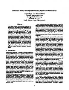
(11) where f (X ), g (X ) and h (X ) are objective function, inequality and equality constraints according to Eq. (10) and r is a penalty factor. For economic design of retaining wall, the objective function, design variables and design constraints should be defined explicitly. In the following sections a description of these parameters for optimization of retaining structures are presented. Design variables The cantilever wall generally consists of a vertical stem, and a base slab, made up of two distinct regions, viz. a heel slab and a toe slab (Fig. 1). All three components behave like one-way cantilever slabs: the ‘stem’ acts as a vertical cantilever under the lateral earth pressure; the ‘heel slab’ and the ‘toe slab’ acts as a horizontal cantilever under the action of the resulting soil pressure. Fig. 1. Cross section of the reinforced retaining structure
No. 1 (Jan 2012)
ISSN: 0974- 6846
horizontal steel area of the heel per unit length of wall (X8). In Fig. 1, β is the backfill slop angle; D is the depth of soil in front of the wall; B is the base width of the wall’s foundation; H is the height of stem and q is the surcharge load. Design constraints According to Bowles (1982) and ACI 318-05 (2005), the design constraints may be classified as geotechnical and structural requirements. These requirements represent the failure modes as a function of the design variables. Expressions for factors of safety against overturning failure, sliding failure, eccentricity failure, bearing failure, shear and moment failure of toe slab, heel slab, and stem of the wall are given in the following sections. Overturning failure mode The stabilizing moments must be greater than the overturning moments to prevent rotation of the wall around its toe. The stabilizing moments result mainly from the self-weight of the structure, whereas the main source of overturning moments is the active earth pressure. The factor of safety against overturning is calculated from:
FSOverturning
M M
R
(12)
O
where ∑MR is sum of the moments of forces that tends to resist overturning about point O and ∑MO is sum of the moments of forces that tends to overturn about point O. The factor of safety against overturning must be equal to or greater than 1.5. Sliding failure mode The net horizontal forces must be such that the wall is prevented from sliding along its foundation. The factor of safety against sliding is calculated from:
FS Sliding
F F
R
(13)
d
Fig.1 shows the cross-section of a reinforced earth retaining structure. The eight design variables consist of the width of heel (X1), the stem thickness at the top (X2), the stem thickness at the bottom (X3), the width of toe (X4), the thickness of base slab (X5), the vertical steel area of the stem per unit length of wall (X6), the horizontal steel area of the toe per unit length of wall (X7) and the Research article Indian Society for Education and Environment (iSee)
where ∑FR is sum of the horizontal resisting forces and ∑Fd is sum of the horizontal driving forces. The minimum acceptable limit for FSsliding is 1.5. The most significant sliding force component usually comes from the lateral earth pressure acting on the active (backfill) side of the wall. Such force may be intensified by the presence of vertical or horizontal loads on the backfill surface. Bearing failure mode The bearing capacity of the foundation must be large enough to resist the stresses acting along the base of the structure. The factor of safety against bearing capacity failure is calculated from: qult FS Bearing Capacity (14) qmax where qult is the ultimate bearing capacity of the foundation soil and qmax is the maximum contact pressure at the interface between the wall structure and the
“Gravitational search algorithm” http://www.indjst.org
M.Khajehzadeh et al. Indian J.Sci.Technol.
1824 Vol. 5
Indian Journal of Science and Technology foundation soil. The minimum acceptable value for FSBearing Capacity is 3.0. Eccentricity failure mode For stability, the line of action of the resultant force must lie within the middle third of the foundation base. For safety against eccentricity failure the following equation should be satisfied:
e
B 6
(15)
where B is the base width of the wall and e is the eccentricity of the resultant force. Toe shear and moment failure mode Toe slab of the wall has to be designed as a cantilever slab to resist moments and shear forces. The net loading acts upwards and flexural reinforcement has to be provided at the bottom of the toe slab. To prevent toe shear failure, nominal shear stress at the junction of stem with toe slab should be less than shear strength of concrete. Factor of safety against toe shear failure is defined:
FStsh
c vtoe
(16)
where τc is the shear strength of concrete and τvtoe is the nominal shear stress. A critical section for the moment is considered at the junction of stem with toe slab. Factor of safety against toe moment failure is defined as:
FStm
M Rtoe MUtoe
(17)
No. 1 (Jan 2012)
ISSN: 0974- 6846
where MUheel is the maximum bending moment at a vertical section at the junction of the stem with heel slab and MRheel is the resistance moment of the heel slab. Stem shear and moment failure mode The stem of the wall has to be designed as cantilever slab to resist moments and shear forces. Nominal shear stress of stem (τvstem) should be less than shear strength of concrete (τc). Factor of safety against stem shear failure is defined as:
FS hsh
c vstem
`
(20)
Moreover, maximum bending moment at the face of the support (MUstem) should be less than the resistance moment of stem (MRstem).
FSsm
M Rstem MUstem
(21)
Maximum deflection at the top of the stem As recommended by Yepes et al. (2008), the maximum deflection at the top of the stem should not exceed an acceptable threshold level (1/150 height of the stem).
max
H 150
(22)
where δmax is the maximum deflection at the top of the stem and H is the height of the stem. Upper bound and lower bound constraints In addition to the above constraints and based on Bowles (1982) and ACI 318-05 (2005), all design variables have practical minimum and maximum value. The lower and upper bounds of the design variables are summarized in Table 1.
where MUtoe is the maximum bending moment at a vertical section at the junction of the stem with toe slab and MRtoe is the moment of resistance of toe Table 1. Upper bound and lower bound for design variables of retaining wall slab. Description Lower bound Upper bound Heel shear and moment failure Thickness of base slab X5min = H/12 X5max = H/10 mode Width of toe X4min = 0.4 H/3 X4max = 0.7 H/3 Heel slab of the wall has to be Width of footing Bmin = 0.4 H Bmax = 0.7 H designed as a cantilever slab to Stem thickness at the top X3min = 20 cm resist moments and shear forces. Vertical steel area of the stem X6min = 0.0033(X2+ X3-0.07) X6max = 0.016(X2+ X3-0.07) The net loading acts downwards Horizontal steel area of the toe X7min = 0.0033(X5-0.07) X7max = 0.016(X5-0.07) and flexural reinforcement has to Horizontal steel area of the heel X8min = 0.0033(X5-0.07) X8max = 0.016(X5-0.07) be provided at the top of the heel Objective function slab. Critical section for the shear is considered at the The total cost of the retaining structure is considered junction of stem with heel slab. Thus Nominal shear as the objective function for the analysis to be carried out. stress at this section (τvheel) should be less than shear Thus the cost function may be expressed in the form of strength of concrete (τc). Factor of safety against heel below: shear failure is defined as: (23) f X C cVc C eVe CbVb C f A f C sWs
FS hsh
c
vheel
(18)
A critical section for the moment is considered at the junction of stem with heel slab. Factor of safety against heel moment failure is defined as:
FShm
M Rheel MUheel
Research article Indian Society for Education and Environment (iSee)
(19)
where, Cc, Ce, Cb, Cf and Cs show the unit price of concrete, excavation, backfill, formwork, and reinforcement respectively. In addition, Vc ,Ve and Vb denote the volume of concrete, excavation and backfill, Af shows the area of formwork and Ws indicates the weight of steel. In current study, unit price for these items are given according to Table 2 (Yepes et al., 2008).
“Gravitational search algorithm” http://www.indjst.org
M.Khajehzadeh et al. Indian J.Sci.Technol.
1825 Vol. 5
Indian Journal of Science and Technology Table 2. Retaining structure assembly unit price (Yepes et al., 2008) Item Unit Unit price (USD/m) 3 Earth removal m 3.01 2 Foundation formwork m 18.03 2 Foundation formwork m 18.63 Reinforcement kg 0.56 3 Concrete in foundations m 50.65 3 Concrete in stem m 56.66 3 Earth fill-in m 4.81
Finally, the main objective function may be obtained by substituting the objective function of Eq. (23) and inequality constraints presented in section 3.2, into Eq. (11). Numerical examples This section investigates the validity and effectiveness of the proposed algorithm to optimum design of retaining structures. The implementation procedure of the GSA for the optimization of the retaining structures is shown as a flowchart in Fig. 2. To verify the good performance of the proposed algorithm, two numerical examples of retaining structures will be solved by the presented method. The procedure has been carried out using a computer program coded in MATLAB. All the programs were executed on a 2.10 GHz Pentium IV processor with 2GB of random access memory (RAM). To achieve the optimum performance in the proposed methodology, proper fine tuning of GSA’s parameters is evaluated by several experimental studies examining the effect of each parameter on the final solution of the algorithm. As a result, parameters of GSA are set as follows: population size is 50; maximum iteration number is 1000; G0 = 100; β = 20. The optimization procedure was terminated when the maximum number of iterations is reached. Moreover, to verify the efficiency of the proposed algorithm, the result of the GSA is compared with the results of genetic algorithm (GA) and particle swarm optimization (PSO). For the purpose of optimization by GA the routine from Input parameter
No. 1 (Jan 2012)
Fig. 2. Flowchart showing the application of GSA for optimization of retaining structure
genetic algorithm optimization toolbox of MATLAB is used (The Math works Inc. 2009). Example 1 In this example, the optimum design of a retaining structure with height of 3.5m by GSA is presented. Other input parameters for this problem are given in Table 3. To demonstrate the efficiency of the proposed GSA method, the problem is analyzed using genetic algorithm (GA) and particle swarm optimization (PSO). The optimization results of all algorithms are tabulated (Table
Table 3. Input parameters for optimum design of retaining wall Unit Value for Example 1
Height of stem Internal friction angle of retained soil Internal friction angle of base soil Unit weight of retained soil Unit weight of base soil Unit weight of concrete Cohesion of base soil Depth of soil in front of wall Surcharge load Backfill slop Concrete cover Yield strength of reinforcing steel Compressive strength of concrete Shrinkage and temporary reinforcement percent Factor of safety for overturning stability Factor of safety against sliding Factor of safety for bearing capacity Research article Indian Society for Education and Environment (iSee)
m degree degree 3 kN/m 3 kN/m 3 kN/m KPa m KPa degre cm MPa MPa -
ISSN: 0974- 6846
3.5 30 0.0 16 18 24 125 0.5 25 10 7.0 140 21 0.002 1.5 1.5 3.0
“Gravitational search algorithm” http://www.indjst.org
Value for Example 2 5.0 34 0.0 17 18 24 100 0.75 35 0.0 7.0 140 21 0.002 1.5 1.5 3.0 M.Khajehzadeh et al. Indian J.Sci.Technol.
1826 Vol. 5
Indian Journal of Science and Technology Table 4. Optimization result for retaining structure- Example 1 Design variable Unit GSA PSO Width of heel (X1) m 0.96 1.12 Stem thickness at the top (X2) m 0.25 0.37 Stem thickness at the bottom (X3) m 0.23 0.28 Width of toe (X4) m 0.9 0.59 Thickness of base slab (X5) m 0.32 0.32 2 Vertical steel area of the stem (X6) cm 20.4 15 2 Horizontal steel area of the toe (X7) cm 11.5 6.3 2 Horizontal steel area of the heel (X8) cm 7.3 6.0 Best price (USD/m) 354 378
ISSN: 0974- 6846
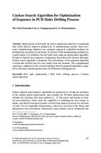
Fig. 4. Convergence rate of the algorithms for example 2 GA 1.48 0.27 0.23 0.52 0.37 32 9.7 6.0 399
4). The results showed that the minimum price of the retaining structure obtained by GSA is 354 (USD/m) which is lower than those calculated by PSO (378 USD/m) and GA (399USD/m). In this case, the GSA could improve the results of PSO and GA methods more than 6 and 11 percent, respectively. Fig. 3. Convergence rate of the algorithms for example 1
No. 1 (Jan 2012)
algorithms for the optimum design of the optimization problem considered. As can be seen, in addition to generating superior results, the GSA has a very fast convergence rate in the early iterations and performed significantly better than other methods. Conclusion This study presents an effective method based on gravitational search algorithm (GSA) for optimum design of retaining structures. The proposed method is classifiable as direct search algorithms and does not require any continuity or derivatives of the objective function. During the optimization procedure, eight design variables are treated, which vary within the ranges of geotechnical and structural requirements. A computer program is developed in MATLAB and the user is only required to feed the input parameters like soil and material properties and safety factors. The efficiency and accuracy of the presented method were investigated through the two numerical examples of retaining walls. To further validate the effectiveness of the presented strategy, the results of GSA are compared with the results of GA and PSO methods. For the studies carried out here, it is found that gravitational search algorithm is a suitable technique for optimization of retaining structures and the method is able to find a better optimal solution compared with particle swarm optimization and genetic algorithm.
Fig.3 shows the variation in best price obtained by different methods through the optimization procedure. It is obvious that the proposed algorithm requires far fewer iterations and less computational time when compared with other algorithms. Overall speaking, the proposed algorithm has been shown to perform extremely well for solving economic design of retaining structure. Table 5. Optimization result for retaining structure- Example 2 Example 2 Design variable Unit GSA PSO GA Optimization of a retaining wall with height of 5.0m Width of heel (X1) m 1.35 1.9 1.45 is investigated in this example. Other input parameters Stem thickness at the top (X2) m 0.36 0.36 0.5 for this example are given in the last column of Table Stem thickness at the bottom (X3) m 0.28 0.28 0.3 3. This case also solved by GSA, PSO and GA m 1.14 0.8 0.93 methods. The optimization results are summarized in Width of toe (X4) Table 5. Table 5 also shows the comparison between Thickness of base slab (X5) m 0.45 0.45 0.45 2 the results obtained by all methods. As derived from Vertical steel area of the stem (X6) cm 32 32 32 2 Table 5, the best price evaluated for this case by GSA Horizontal steel area of the toe (X7) cm 16 12 13 is 626 USD/m. However, the best price achieved by 2 Horizontal steel area of the heel (X8) cm 12 12 12 PSO is 647 USD/m and by GA is 677 USD/m. Best price (USD/m) 626 647 677 Fig.4 presents a performance comparison of three Research article Indian Society for Education and Environment (iSee)
“Gravitational search algorithm” http://www.indjst.org
M.Khajehzadeh et al. Indian J.Sci.Technol.
1827 Vol. 5
Indian Journal of Science and Technology
No. 1 (Jan 2012)
ISSN: 0974- 6846
References 1. ACI Committee 318 (2005) Building Code Requirements for Structural Concrete (ACI 318-05) and Commentary (318R-05). American Concrete Institute, Farmington Hills, Mich. 2. Bowles J (1982) Foundation analysis and design. McGraw-Hill, NY. 3. Ceranic B, Fryer C and Baines RW (2001) An application of simulated annealing to the optimum design of reinforced concrete retaining structures. Comput. Struct. 79,1569–1581. 4. Khajehzadeh M, Taha MR, El-Shafie A and Eslami M (2011) Modified particle swarm optimization for optimum design of spread footing and retaining wall. J. Zhejiang Univ–Sci A (Appl. Phys. & Eng.). 12(6), 415-427. 5. Rashedi E, Nezamabadi-pour H and Saryazdi S (2009) GSA: a gravitational search algorithm. Inform. Sciences. 179(13), 2232-2248. 6. Saribas A and Erbatur F (1996) Optimization and sensitivity of retaining structures. J. Geotech.l Eng. 122, 649-656. 7. Sivakumar Babu GL and Munwar Basha B (2008) Optimum design of cantilever retaining walls using target reliability approach. Int. J. Geomech. ASCE. 8(4), 240-252. 8. The Math works Inc (2009) Genetic Algorithm and Direct Search Toolbox for use with Matlab user’s guide. Version 7.8.0.347, Release R2009a. 9. Yepes V, Alcala J, Perea C and González-Vidosa F (2008) A parametric study of optimum earth-retaining walls by simulated annealing. Eng. Struct. 30(3), 821830.
Research article Indian Society for Education and Environment (iSee)
“Gravitational search algorithm” http://www.indjst.org
M.Khajehzadeh et al. Indian J.Sci.Technol.