Hardware Support for a Hash-Based IP Traceback1 Luis A. Sanchez,2 Walter C. Milliken, Alex C. Snoeren, Fabrice Tchakountio, Christine E. Jones, Stephen T. Kent, Craig Partridge, and W. Timothy Strayer BBN Technologies 10 Moulton St. Cambridge, MA 02138
[email protected] {milliken,snoeren,ftchakou,cej,kent,craig,strayer}@bbn.com
Abstract The Source Path Isolation Engine (SPIE) is a system capable of tracing a single IP packet to its point of origin or point of ingress into a network. SPIE supports tracing by storing a few bits of unique information about each packet for a period of time as the packets traverse the network. Software implementations of SPIE can trace packets through networks comprised of slow to medium speed routers (up to OC-12), but higher speed routers (OC-48 and faster) require hardware support. In this paper, we discuss these hardware design aspects of SPIE. Most of the hardware resides in a self-contained SPIE processing unit, which may be implemented in a line card form factor for insertion into the router itself, or as a stand-alone unit that connects to the router through an external interface.
1. Introduction Today’s Internet infrastructure is vulnerable to motivated and well-equipped attackers. Much work is being done to safeguard resources, detect an attack, and, if possible, attempt to thwart the attack. A more difficult problem is determining the origins of an attack. Accurate and reliable identification of attackers is currently extremely difficult because the network routing infrastructure is stateless and based largely on destination addressesno records are kept in the routers, and the source address is not trustworthy. The attacker can generate offending IP packets masquerading as having originated almost anywhere, including from IP 1 2
addresses that are not globally unique, such as those used to create private networks [1]. In general, attacks against sites or even the network infrastructure can be waged from the safety of complete anonymity. One method to expose the true origin of a packet is to support after-the-fact single packet traceback. Locating the point of attack is a first step towards both blocking the attack and identifying the party who launched the attack. There are several approaches to determining the route of attack packets. Burch and Cheswick proposed inferring the route by using a controlled flooding scheme and watching for variations in the received packet flow [2]. Bellovin has proposed using ICMP messages to provide authenticated marking of packets [3]. Savage et al. proposed a probabilistic marking approach where routers mark packets with partial path information during packet forwarding [4]. After a victim has received a substantial number of packets, it can reconstruct the entire path by combining the pieces of path information embedded in each packet. Song and Perrig point out that this scheme gives a large number of false positives when the attack comes from multiple sources, and suggest improved and authenticated marking schemes with less packet overhead and higher precision [5]. In general, these schemes are targeted at the typical denial-of-service attack that Internet sites experience today [6] and require a large number of the attacking packets be sent during the detection phase. Attacks that require only a few packets are generally not traceable by these techniques. Yet, it is known that a single packet attack can render a host inoperable for hours. WinNuke, Teardrop, and NewTear [7] are examples of single-packet attacks that exploit vulnerabilities in packet processing of popular TCP/IP stack implementations.
This work was performed under DARPA contract N66001-00-C-8038 At the time the work described in this paper was completed, Mr. Sanchez was an employee of BBN Technologies.
The obvious approach to single packet traceback is simply to log packets at various points throughout the network, and then use appropriate extraction techniques to discover the packet’s path. Logging requires no computation on the router’s fast path, and hence can be implemented efficiently in today’s router architecture. However, the effectiveness of the logs is limited by the amount of space available to store them and the internal data bandwidth available to copy the packets as they pass through the router. Given today’s link speeds, packet logs quickly grow to intractable sizes, even over relatively short time frames. An OC-192 link is capable of transferring 1.25GB per second. If one allows 60 seconds to discover an attack and conduct a query, a router with 16 links would require 1.2TB of high-speed storage. Sampling techniques can lessen these requirements but also reduces the probability of detecting small flows. Alternatively, routers can be tasked to perform more sophisticated auditing in real time, extracting a smaller amount of information as packets are forwarded. Many currently available routers support input debugging, a feature that identifies on which incoming port a particular outgoing packet (or set of packets) of interest arrived. Since no history is stored, however, this process must be activated while the flow of interest is currently passing through the router. Furthermore, due to the high overhead of this operation on many popular router architectures, activating it may have adverse effects on the traffic currently being serviced by the router. Both Sager [8] and Stone [9] have proposed sophisticated logging of router events for attack analysis, but both schemes introduce significant processing and storage overhead in the routers. Schnackenberg et al. propose a special Intruder Detection and Isolation Protocol (IDIP) to facilitate interaction between routers involved in a traceback effort [10]. IDIP does not specify how participating entities should track packet traffic; it simply requires that they be able to determine whether or not they have seen a component of an attack matching a certain description. SPIE, the Source Path Isolation Engine, is a system that provides traceback capability on a per-packet basis. SPIE-enabled routers record tiny digests of each packet as it passes. These digests are kept for a period of time long enough to allow after-the-fact traces of the packet. At medium to high speeds, however, calculating and storing the packet digests requires hardware assistance. SPIE’s design allows this support to be provided through a combination of simple modifications to current router line cards and a limited amount of additional hardware. A full description of SPIE and an analysis of its effectiveness are given in [11]. In this paper, we present in detail the hardware components of the SPIE system which provides hash-based single packet traceback.
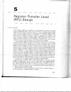
2. SPIE System Overview SPIE is a system of components that records packets passing through routers and provides the ability to reconstruct a particular packet’s path given the packet, where the packet was destined, and an approximate time the packet was received. Figure 1 shows the relationship between the SPIE components. A SPIE-enabled router contains a special process called a Data Generation Agent (DGA). A DGA logs each packet as it passes through the router by calculating a 32bit digest of the packet. The digest is constructed by applying a collision-resistant hash over selected fields in the packet, and is stored in a digest table as a bitmap of Bloom filters [12] to conserve memory. The digest table, therefore, is a compact representation of all of the traffic served by the router over a given time period. The amount of memory dedicated to the DGA dictates the size of the digest table and how long it is used before a new digest table is constructed. Old digest tables are timestamped and kept as long as the router’s resources allow. A SPIE Collection and Reduction Agent (SCAR) is responsible for several routers in a region of the network. The SCAR asks the routers to dump all of their digest tables when a request for traceback is made. Once on the SCAR, analysis is no longer time constrained. The SCAR examines each router’s cache to construct a subgraph of the trace. The trace requests come from a central controller called the SPIE Traceback Manager (STM). This controller is responsible for authenticating all requests, querying the appropriate SCARs, and constructing the complete attack graph from the SCARs’ subgraphs. When an intrusion detection system discovers a suspicious packet, it contacts the STM with the packet, the destination node, and the time at which the packet was received (we assume clock synchronization among participating nodes to correctly correlate packet arrivals, such as NTP [13]). The STM authenticates the request for traceback and directs all DGAs to dump their digest tables to their SCARs. Then, beginning at the SCAR responsible for the victim’s region of the network, the STM sends a query message consisting of the packet information provided by the IDS. The SCAR responds with a partial attack graph. The attack graph either terminates within the region managed by the SCAR, in which case a source has been identified, or it contains nodes at the edge of the SCARs network region, in which case the STM sends a query to the SCARs abutting those edge nodes. This process continues until all branches of the attack graph terminate either at a source within the network or at the edge of the SPIE system. The STM then constructs a composite attack graph, which it returns to the IDS.
DGA
DGA
Router Router Router
Router Router
SCAR
Router
ISP's Network DGA
Router
STM
Router
Figure 1: SPIE network infrastructure. SPIE requires very little data to be kept per packet: only a few bits. One consequence of storing so little information is that packet identification is based on probability. Due to the probabilistic nature of Bloom filters, a SCAR or DGA cannot be sure that the actual packet P was seen at a particular router. Rather, it can determine either that, with very high probability, P was seen, or with certainty that P was not seen. As a result, SPIE will always provide a trace path to the packet’s origin, but may also generate additional spurious false paths. By varying the hash functions across routers and time periods, SPIE attempts to limit the effect of spurious matches at any particular router. The hash functions used by the Bloom filters may be quite lightweight. Intuitively, one might expect that an attacker might try to cause hash function collisions, concealing attack traffic. However, causing hash collisions yields no advantage. If the attacker seeks to make the attacking packets from different sources look alike (e.g., hash to the same value), the resulting SPIE trace will simply be a tree-shaped path (from one destination back to multiple sources) revealing all the entry points from which the hacker can attack. And making each packet look different simply means that each packet can be uniquely traced to its origin.
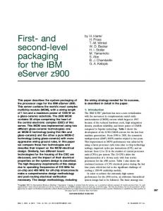
3. Hardware Design Data Generation Agents are the primary hardware components of the SPIE system. The entire system depends on their functionality and feasibility. One particular concern is the ability to implement DGAs for very high data rate interfaces. Here we present the issues of implementing DGAs in hardware, with a particular focus on high performance implementations. Figure 2 illustrates the key components of the SPIE hardware. Most of the hardware exists in a self-contained SPIE processing unit, which may be implemented in a line card form factor for insertion into the router itself, or
as a stand-alone unit that connects to the router through an external interface. In either case, all interfaces on the router must be extended to support data collection through the implementation of signature taps. The signature tap is a relatively simple piece of hardware that computes n independent 32-bit digests (S32 in the diagram) of each packet that arrives on a SPIEcapable interface. These digests are then passed to the SPIE processing unit on a separate signature bus. The signature aggregation stage of the SPIE card produces a periodic digest table of size 2k bits (where k is at most 32), covering a time interval R, which is then stored in a large bulk history memory organized as a time-slotted ring buffer containing the past digest tables. Entire digest tables in the history memory, indexed by collection interval, can be transferred to the control processor on demand for transmission to a SCAR. Generally, due to network latencies and timing uncertainties in the arrival time of a packet of interest at a given router, several tables will need to be fetched surrounding the estimated time of packet arrival. Note that different systems can choose different values of n, k, and R, as long as they report how each of the n digests are computed, which k bits of the 32 digest bits are used, and the time span covered by each digest table sent in response to a query. Selection of appropriate values of n, k, and R is discussed after a more detailed description of each individual stage of the hardware design.
3.1. Signature Taps The signature taps produce digests of each IP packet seen by the interface. In order to eliminate false positives during SPIE traceback, the digesting functions are different at each router. While our analysis presumes independently random digesting functions at each router, we propose to use a salted CRC-32 for high-speed implementations. Previous studies have shown that CRC32 performs quite well on typical input streams [14], and is significantly cheaper to implement in hardware than traditional hash functions. A salted CRC is one in which the CRC function begins its computation with a random 32-bit initial value. In the DGA, a different initial value is chosen for each of the n digests. Furthermore, the initial value may be changed each time the digest tables are saved into the history memory. This approach ensures that packets are represented by n distinct digests at each router, every packet received at the router during a specific time interval is associated with the same set of digest functions, and, further, that digest table collisions are (empirically, at least) independent. Each packet digest is determined by computing a salted CRC-32 of the IP packet header and the first 64 bits of the packet payload. However, the IP options, TTL,
checksum, and TOS header fields are zeroed out since they change frequently in transit. Router line cards can be easily modified to include signature taps; in some routers, the IP forwarding engine may be able to compute signatures during the forwarding process. In other architectures, it may make more sense to place the signature tap on the output of the ingress layer-2 packet framer. In any event, the amount of logic required to compute a CRC-32 digest is small, and easily added to most line cards. Signature taps can be connected to the SPIE processing unit in several ways. For lower-speed routers, a simple serial interface with specialized framing will suffice. Depending on the form factor, the serial link could be routed over the back plane to an in-chassis SPIE card, or run to an auxiliary external connector on the line card bulkhead for connection to a separate SPIE box. (For OC-192 line cards, a Gigabit Ethernet interface may be a relatively simple way to transmit digests, since the signature bit rate is about 10% of the link rate.) With an external SPIE implementation, it is also possible to put the signature taps in the SPIE box itself, with a set of “feed-through” connectors passing the input signals on to the actual router input ports. This requires the taps to include sufficient logic to extract IP packets from the link. This may be a viable approach for Ethernet interfaces and lower-speed single-channel packet over SONET (POS) interfaces, for which one-chip framers are available.
3.2. Transforms Signature taps do not encompass all packet recording at the router. IP packets may undergo valid transformation (e.g., fragmentation, IPsec tunneling, network address translation) while traversing the network, in which case, packet digests do not sufficiently enable traceback of a packet. Packet transforms must be recorded such that the original packet is able to be reconstructed during the traceback process. Therefore, DGAs record within a transform lookup table (TLT) the hash of a transformed packet, the type of transformation, and sufficient packet data to enable packet reconstruction. Transform information is provided to the DGA by the control processor because packets that undergo transformation are generally routed through the control path of the router. DGAs record and store within the history memory a corresponding TLT for every packet digest table. Accordingly, digest table/TLT pairs are read out of the history memory to service a SPIE traceback query. For a more in-depth discussion of SPIE’s handling of packet transformation, refer to [11].
Line Cards
SPIE Card (or Box) FIFO
RAM MUX
S32
Ring Buffer DRAM t
2k-bit RAM
Sk S32 readout every R ms
+
S32
.. .
S32
.. .
.. .
Time =t
t-P s
S32
Signature Taps
Readout by Control Processor
Signature Aggregation
History Memory
Figure 2: An example SPIE DGA hardware implementation for high-speed routers.
3.3. Signature Aggregation Once the digests arrive at the processing unit, they are aggregated into digest tables representing the traffic serviced by the router over a small time interval (the parameter R in the diagram). The particular aggregation implementation shown in the diagram is designed to be scalable to very high-speed routers, with relatively low implementation cost. Much simpler designs are possible for lower-speed routers. The aggregation interface may need to be multi-ported for routers with high-speed interface links. Arriving digests on each port are placed into a small FIFO, which feeds a simple arbitrating multiplexer that controls access to an aggregation memory for several input ports. A specified set of k bits from each 32-bit packet digest is considered a table index, and the appropriate bit in the aggregation memory is set accordingly. Every R milliseconds, the memory contents are copied out and ORed with the contents of other signature memories on the card, producing a global digest table of size 2k for the entire router, which is passed on to the history memory for archival. This record represents the traffic set for the prior R millisecond interval, and is labeled appropriately. Each memory location is cleared while being read out. The aggregation memory may use a ping-pong doublebuffering scheme to avoid race conditions, but this doubles the memory size. It may also be acceptable to only lock the location that is being read out until it is cleared, since this only adds additional R latency to the timing uncertainty of a packet being traced. For low-speed routers, in which the total packet arrival rate is about 10 Mpkts/sec or less, the aggregation stage may be eliminated in favor of setting digest bits directly in the current slot of the history memory. Low-speed routers also need much less history memory, of course, since the signature memory fills up more slowly.
3.4. Aggregation Rationale SPIE must scale to very high speeds while still allowing the individual packet histories to be queried for many seconds. The main purpose of the intermediate aggregation stage is to fulfill this requirement through the use of two disparate memory types, SRAM and DRAM. Recall that SRAM maintains high access rates (e.g., 10 ns/access), at the expense of cost and heat dissipation. DRAM, on the other hand, is much denser, requires less power, and is considerably less costly for equivalent amounts of memory, but suffers from diminished access rates (e.g., 50 ns/access), although high throughput rates of 3.3 ns are common. The signature aggregation phase allows SPIE to take advantage of both SRAM and DRAM to enhance scalability. In a high-end router with 32 OC-192 interfaces, the combined packet arrival rate is about 640 Mpkts/sec, requiring about 3.125 Gbits of memory per second of history kept (for a typical Bloom filter configuration of n= 3 [11]). An intrusion detection system may take a few minutes to report an intrusion and request a traceback, requiring a few 100s of Gbits of memory at the router. While not totally unreasonable for current generations of DRAMs, it is well out of the feasible cost and power range for an SRAM-based history memory. So a staging mechanism is required to transfer the digests from the high-speed portion of the interface (where SRAM is required) to an area running at DRAM speeds. In addition to the overall capacity of the memory banks, technology limitations on access time are also an important design consideration. The signature collection process requires four memory accesses per packet: a random read-write pair to set a single bit in the typical Nbit-wide memory device, and a sequential read-write pair during the periodic readout/clearing process. Assuming a single DRAM is used for aggregation, and the sequential readout process takes negligible time (due to its sequential nature, which can benefit from both the DRAM word width and single-row burst transfers), the SPIE collection process is limited to at most 20 Msignatures/sec (assuming a rather optimistic DRAM cycle time of 50ns for a random-address read-modifywrite cycle). Thus DRAM performance is far too low for most core routers, as a rate of 20 Msignatures/sec is only enough to support the typical peak packet rate on a single OC-192 link, or four OC-48 interfaces. A solution that can handle on the order of 32 OC-192 interfaces on a core router is desired, preferably without requiring large amounts of expensive, fast memory. A router of this capacity requires SPIE to process approximately 1.92 Gsignatures per second. A design based on a single SRAM is plausible, but both read and write accesses would then require a full memory access time. Assuming a 16-bit wide device, the
readout process can again be assumed to be negligible. Assuming somewhat optimistic 5ns cycle times per read or write, up to 100 Msignatures/sec can be accommodated. This is still well below the rate required for the next-generation core routers described above, but might suffice for routers from the current OC-48 generation. Therefore, the requirements of high-end routers lead to the design of Figure 2, using multiple signatures SRAMs and additional aggregation at the digest table level. Each aggregation SRAM is shared by as many SPIE ports as will comfortably fit within its performance limit. If we choose to use relatively cheap and dense SRAMs, a 10ns access time is reasonable, supporting about 50 Msignatures/sec. This is sufficient for one OC-192 link, using a simple time-multiplexing scheme. It may also be feasible to use DRAMs for the firstlevel signature memory for a single OC-192 link, but this requires the highest speed grades available, and an SRAM solution may actually be more cost-effective. A 1.92 Gsignature/sec SPIE unit supporting a 32-port OC-192 router requires about 12 to 16 of the SRAM-based firstlevel aggregation memories. All of these memories are then read out in parallel, with the outputs ORed together, to produce a single global digest table to pass to the history memory.
3.5. History Memory The history memory, rather than being a single digest table for increasingly long intervals, is instead a ring buffer of many short-interval digest tables. The size can be easily tailored to meet detection and reporting latency requirements of up to a minute or so, even for high-end core routers, for a relatively low cost. At each time interval, R, the current digest table from the aggregation stage is written starting at the current point in the ring (overwriting the oldest entry), and the write address is advanced by one table length. The control processor may sporadically read out the history memory slot for a specific time in order to service a query request, as long as that time is not older than the oldest entry in the ring. Generally, it will need to request more than one digest table for a given trace attempt, since boundary effects at the ends of the collection interval and timing uncertainties in the overall system will widen the time interval to be examined. Since the history memory is always read and written in large blocks, DRAM memory is well suited, being both sufficiently dense and relatively inexpensive. The length of the history buffer is constrained by the tradeoff between the desire for longer storage times (allowing tracebacks triggered by slower intrusiondetection systems) and cost and engineering considerations due to the DRAM technology available.
The history memory cost will likely dominate the cost of the SPIE board or box. Assuming the 32-port OC-192 router example, with a 16Mb digest table every 5ms, a single current-generation 256Mb DRAM can store about 80ms of history. (Note that the input data bandwidth is about 3Gb/s, which is within the range of feasibility for DRAMs performing sequential memory accesses.) A buffer of 30 seconds requires 375 of these devices, which is barely within the range of feasibility; if new 1Gb DRAMs were used, the memory array would require a much more reasonable 94 chips. With current DRAM memory prices below $1/MByte, this is less than $12k worth of memory. This seems a very reasonable cost to support a 32-port OC-192 router.
3.6. Parameter Selection The values of n, k, and R are driven primarily by the tradeoff between reasonable implementation speed, size, and cost of the first-level signature memory. These values will also be driven by the desire to minimize the number of digest tables in the history memory that might contain a packet of interest, arguing for a larger digest table size (which takes longer to fill). Using a 3-way Bloom filter (meaning three independent digests are stored for each packet), a single current-generation 16Mb 10ns SRAM shared by two OC192 ports (40 Mpkts/sec) fills to useable capacity (approximately 5 bits per packet [15]) in about 80ms. However, we need to combine up to 16 of these for a 32port OC-192 router, so the actual R value needs to be 1/16th of this, or about 5ms. This may be an acceptable value for R, since the typical network round-trip delay (about 100ms) bounds the likely timing uncertainty of a packet to about 20 tables at worst, and it is significantly larger than the time synchronization error for NTPsynchronized systems. As few as two tables may be needed, if packet timing is known more precisely.
4. Conclusion It is worth stepping back from the details of the hardware design presented to look at the larger message. The architecture of a SPIE DGA requires the computation of n digest values, each k bits long. Given an average Internet packet size of between 1K and 2K bits, an n of 3, and a k of at most 32, the data rate of digests being produced is between 5% and 10% of the link bandwidth. When link bandwidths are large (e.g., 10s of gigabits), those portions become challenging numbers. Yet, the final amount of data that must be stored is fairly small. SPIE stores the digest values in a bitmap, thus reducing the digest cost from k to one or two bits. So, in the end, the cost of keeping SPIE data is only about 6
bits per packet or between 0.3% and 0.6% of the link bandwidth. This is a very manageable data rate, even at high link bandwidths. The challenge, therefore, in high performance SPIE systems is to find a method to reduce the volume of SPIE data being handled from k bits to one or two bits as swiftly as possible. In this paper we achieved this goal using the signature aggregation module described in sections 3.3 and 3.4, along with an efficient implementation of history memory.
5. Acknowledgment We thank Charles Lynn for providing great ideas during the early stages of this work. We also thank John Lowry for his encouragement and many helpful discussions.
6. References [1] Y. Rekhter, B. Moskowitz, D. Karrenberg, G. J. de Groot, and E. Lear, “Address Allocation for Private Internets,” IETF Network Working Group, RFC 1918, Naval Research Laboratory, February 1996. [2] H. Burch, B. Cheswick, “Tracing Anonymous Packets to Their Approximate Source,” Proc. USENIX LISA ’00, December 2000. [3] S. Bellovin, ICMP Traceback, Message to the IETF ICMP Traceback WG, http://www.research.att.com/~smb [4] S. Savage, D. Wetherall, A. Karlin, and T. Anderson, Technical Report UW-CSE-00-02-01, “Practical Network Support for IP Traceback,” Proc. ACM SIGCOMM ’00, August 2000. [5] D. Song and A. Perrig, “Advanced and Authenticated Marking Schemes for IP Traceback,” Proc. IEEE INFOCOM 2001, April 2001. [6] Computer Emergency Response Team. Cert advisory ca2000-01 denial of service developments. http://www.ceet.org/advisories/CA-2000-01.html.2000. [7] Microsoft Corporation. Stop 0A in Tcpip.sys When Receiving Out Of Band (OOB) Data, http://support.microsoft.com/support/kb/articles/Q143/4/78.asp [8] G. Sager, “Security Fun with ocxmon and cflowd”, Presentation at the Internet 2 Working Group, November 1998. http://www.caida.org/projects/NGI/content/security/1198. [9] R. Stone, “Centertrack: An IP overlay network for tracking DoS Floods,” Proc. of 9th USENIX Security Symposium, August 2000. [10] D. Schnackenberg, K., Djahandari, and D. Sterne, “Infrastructure for Intrusion Detection and Response,” Proc.
DARPA Information Survivability Conference and Exposition, January 2000. [11] Alex C. Snoeren, Craig Partridge, Luis A. Sanchez, W. Timothy Strayer, Christine E. Jones, Fabrice Tchakountio, and Stephen T. Kent, “Hash-Based IP Traceback,” BBN Technical Memo 1284, February 12, 2001. [12] B. H. Bloom. “Space/time trade-offs in hash coding with allowable errors,” Communications of the ACM, Vol. 13, No. 7, July 1970, pp. 422-426. [13] D. Mills, “Network Time Protocol Version 3 Specification, Implementation and Analysis,” RFC 1305, UDEL, March 1992. [14] J. Stone, M. Greenwald, C. Partridge, and J. Hughes, “Performance of Checksums and CRCs over Real Data,” IEEE/ACM Trans. on Networking, Vol. 6, No. 5, October 1998, pp. 529-543. [15] L. Fan, P. Cao, J. Almeida, and A. Broder. “Summary cache: a scalable wide-area web cache sharing protocol,” IEEE/ACM Trans. on Networking, Vol. 8, No. 3, June 2000.